Close
0%
0%

Atlas - 6DOF 3D printed universal robot

An Odrive + steppers based construction, with 5x 3D printed hollow shaft reducers and an internal CAN network.

Similar projects worth following
Hi,
I'm creating a 3D printed 6DOF robotic arm (it's my 3,5th attempt), I'm printing my own cycloidal reducers, all 5 of them are hollow shaft, I'm using 8 encoders, 2x BLDC servos (Odrive), 4x stepper motors. The current state of the project is - I've got the robot running, internal communication is working, mechanical side is done, electronics are working as well but still need to be cleaned up, I'm currently learning to use ROS and Moveit! to integrate my robot into the ROS ecosystem.

I'm aiming at sub 0.5mm repeatability without changing load, and sub 2mm repeatability while changing load.

Load capability is 4.5kg max, 2.5kg what I’d call 'nominal'. Load is wrist limited, I was able to lift 9.5 kg at 0.5m with the Axis 1, 2, 3 assembly. Considering the mass of the robot that was about 60Nm at Ax2.

Use case - I’m trying to make it as versatile as possible, the end effector is easily swappable and has power and CAN

Detailed technical description: 

 (ax1 is the base rotation, ax2 the joint just above it, and so on...) 

 For control I use 5X Teensy 3.2 microcontrollers, they are connected together into a single CAN network, (Odrive is also on the same bus). Thanks to that I’m running just 5 cables through the entire thing - one for ground, one for 48V, one for 12v, and two for CAN.   Ax2 - Odrive driven BLDC, 2step reduction - 1:5 belt + 1:24 cycloidal, so 1:120,

Ax3- Odrive driven BLDC, 2step reduction - 1:4 belt + 1:21 cycloidal, so 1:84, 

Two encoders per axis for ax2 and 3. One encoder directly on the motor shaft, 8192PPR, used by the Odrive, and another one,  4096PPR on the joint driven by a dedicated belt(by 'dedicated belt' I mean one that has no load on it, and is used only to transmit rotation from the reducer output to the encoder - this increases precision in comparison to a belt that would be shared between and encoder and a motor) that is , giving 20480PPR for ax2 and 16384  for ax3 (1:5 for ax2; 1:4 for ax3). These ‘on joint’ encoders for ax2 and ax3 are connected to a single teensy, that's running two separate P loops - one for each axis, the output of these two P loops are two velocity commands for the Odrive. These are sent via CAN.

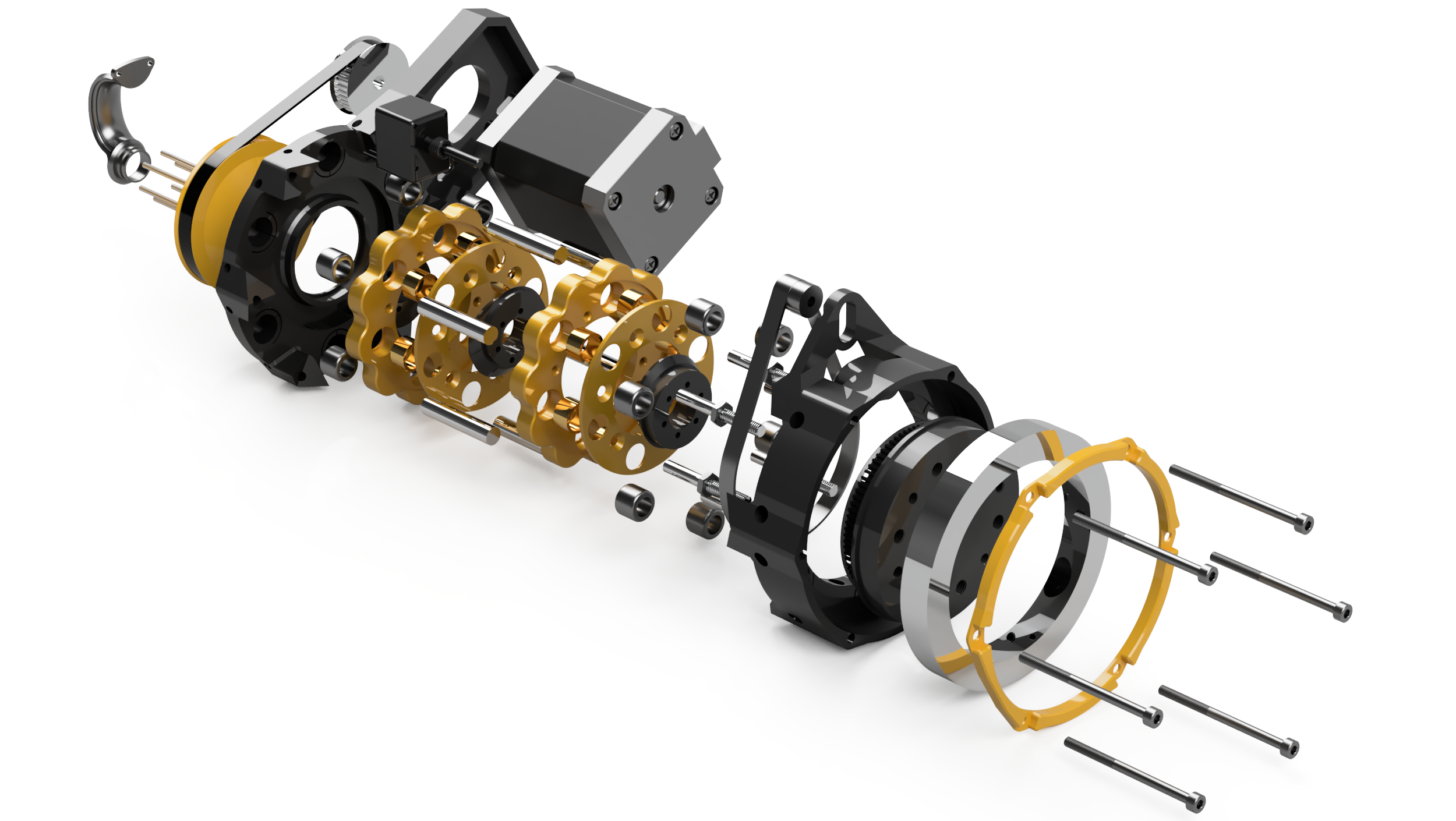
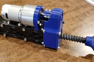
Ax4, 5, 6 - long nema17 steppers, also 2 step reduction, 1:2 belt (adjustable between 1:1 and 1:5 if needed) plus 1:11 cycloidal, so 1:22 total. The reducer I’m using here will be open source, it'll be called OpenCyRe. Each of these 3 wrist axis have their own encoder, driven by a dedicated belt, from the cycloidal gearbox output. The belt increaser is 1:5.25, the encoder is 512PPR, so the resolution of the joint rotation is 2688 for ax4, 5, and 6. Ax5 and ax6 run on the same teensy, and ax4 has its own teensy. That’s because the motor for ax5 and ax6 are not moving in relation to each other. The loop is again a simple P loop for all of these, the input is the ‘on joint’ encoder signal, the output is the frequency at which the stepper is making steps.

Ax1, single step 1:10 belt reduction, Nema 23 stepper motor, the encoder is a 1600PPR one, on a dedicated belt increaser (53:7) that increases the resolution to 11733 PPR  

The 5th teensy is used in the pendant, the pendant has 2x 3axis joysticks, which allows control over all degrees of freedom. This teensy is also supposed to be connectable to the pc, allowing position commands to be sent via serial. 

All axis are capable of 15RPM or more, the robot is capable of handling 2.5kg no problem, and up to 4,5kg if slowed down. The reach is 500mm. The positional repeatability is below 0.5 mm without changing the load, I haven't yet tested repeatability with vs. without load.

Front.jpg

JPEG Image - 3.13 MB - 01/04/2020 at 15:46

Preview

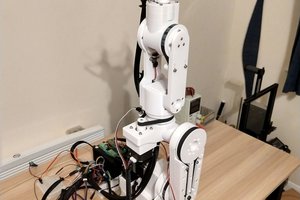
Back.jpg

JPEG Image - 3.28 MB - 01/04/2020 at 15:46

Preview

Encoders setup.png

Portable Network Graphics (PNG) - 1.65 MB - 01/04/2020 at 15:46

Preview

OpenCyRe exploded.png

Portable Network Graphics (PNG) - 1.51 MB - 01/04/2020 at 15:46

Preview

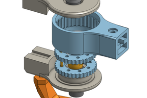
Oś 6 przeniesienie napedu kolor.png

Portable Network Graphics (PNG) - 923.00 kB - 01/04/2020 at 15:46

Preview

View all 21 files

View all 9 project logs

Enjoy this project?

Share

Discussions

Sunny wrote 09/05/2022 at 02:11 point

This looks Amazing! Keep going!

  Are you sure? yes | no

denis perepetskiy wrote 06/03/2022 at 19:57 point

Dear Damian! The project is greate! Thanks for idea.

2ALL

Did anyone get the CAD or STL files from the author?

  Are you sure? yes | no

Pietro Occhi wrote 11/09/2020 at 19:52 point

Dear Damian, I am very impressed by your project: it is very great. I want to ask you if you make available stl file for 3d printing it.

Thank you and good work

Pietro

  Are you sure? yes | no

Björn Ecke wrote 09/08/2020 at 14:52 point

Thats such a cool Robot. Can you pls share your stl-files. Im Part of a Fablab here in Germany (www.home-wgt.de) an it would be very very nice to build this robot <3.

  Are you sure? yes | no

bengamzo22 wrote 09/05/2020 at 22:24 point

Hi you're amazing and I hope you share more videos with us and I really hope once you finish maybe share the files and instructions with the world. Keep up the good work

  Are you sure? yes | no

Marcelo Alcantara wrote 08/04/2020 at 09:37 point

Damien

Amazing project. Please make it available to the community.

Really want to build this.

Cheers

Marcelo

  Are you sure? yes | no

Roy de Kleijn wrote 07/18/2020 at 09:31 point

How cool is this! are you going to share the STL files/ BOM and description ?

  Are you sure? yes | no

Peter wrote 06/26/2020 at 16:11 point

Damien, I love that you've made and shared this arm. I hope that this project is your pride and joy, because it's easy to see the huge amounts of time and effort you've put into making Atlas what it is now. This is so awesome to see.

I'm going to be part of a team designing an arm as a part of the University Rover Challenge competition, and it's looking like we'll at least try prototyping a cycloidal gearbox or two. 

So, for cycloidal gearboxes, do you have a go-to bearing or bushing supplier, and have you found any particular benefits of using bushings over bearings or vice versa? 

Thanks again for posting this amazing feat of engineering. It's very inspiring to see such a complex yet well done project.

  Are you sure? yes | no

Ryanwallace18 wrote 06/16/2020 at 23:53 point

Damien, I saw in your youtube video the robot is using active compliance for force feedback. Is that a ROS library? How did you implement active compliance?

  Are you sure? yes | no

Daniel wrote 02/16/2020 at 21:47 point

Are you programming with Python or Arduino?

  Are you sure? yes | no

Flynt Moreland wrote 11/06/2019 at 23:26 point

Wow!  I'm impressed.  I hope you take the time to share your design and instructions with the world.  I'd certainly consider building one.

  Are you sure? yes | no

MasterOfNull wrote 11/05/2019 at 01:45 point

I like...

The use of lots of small/cheap bearings instead of an expensive (at that size) ring bearing.

That you planned your wire routing from the start.

How you took the time to make the finished product the same color scheme as the renderings.  :)

  Are you sure? yes | no

Dan Maloney wrote 11/05/2019 at 01:00 point

I died a little when that camera took a tumble. But it shows how strong the arm is. Looks great too.

  Are you sure? yes | no

Similar Projects

Does this project spark your interest?

Become a member to follow this project and never miss any updates