-
Project completed
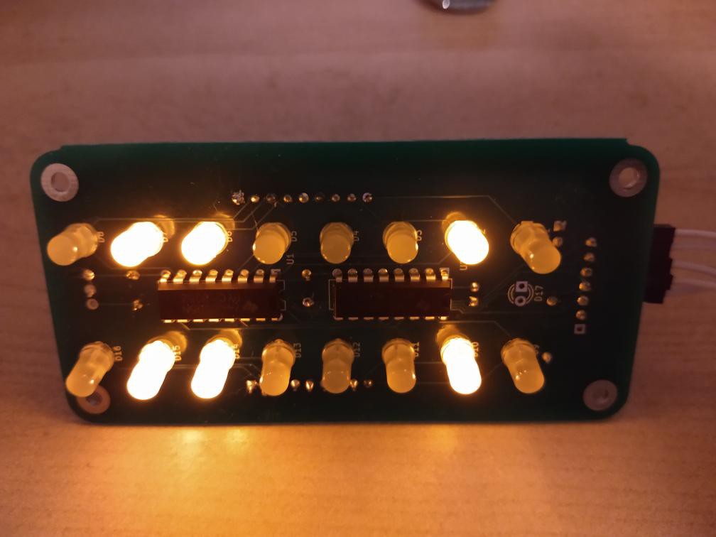
01/02/2020 at 09:01 • 0 commentsThe boards have come back from the fab and I have assembled one, using the same components that were on the breadboard. Aside from one dry joint on one pin of a resistor network, everything works as before.
![]()
So I'm declaring the project finished and I'll update the Github repo. I haven't got any places to use the boards yet.
-
Design released to Github
11/28/2019 at 21:30 • 0 commentsI have released the design files to Github rather than wait for a PCB. The PCB design is untested, but it should work (famous last words).
-
Doing the PCB fab rounds
11/28/2019 at 02:14 • 1 commentDecided to try LocoPCB who support V-cut panelling of a single design for no extra charge. This to experience V-cut panelling and to write a review of my experience with them. LocoPCB also charges $2 for 5 boards, for the first 5 orders. Here is ongoing story until the boards are received.
Previously I checked PCBWay who is having an end of year sale so I decided to see if they'll do panelised PCBs, 2 per board, for the offer price. Unfortunately they want to charge extra for the slot, breaktabs, and mouse bites I put in. But I'll see if I can send another project in to take advantage of the offer.
Then I checked JLCPCB who didn't object to a panelised board last order, and the normal price is good anyway. It turns out from reading their help page that JLCPCB have no extra charge for breaktabs and mouse bites provided it's a single design.
-
Getting the circuit working
11/27/2019 at 05:37 • 0 commentsAs mentioned, the schematic is taken straight out of datasheets so I didn't expect any problems, nor did I encounter any. It was insanely easy to get working.
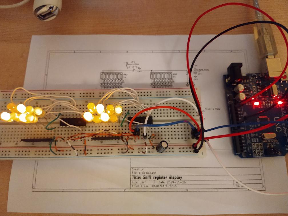
After putting the components on a breadboard, and doing an anti-smoke accident check, I connected it up to an Arduino Uno to test it.
Except for one LED plugged in backwards, which I corrected, the test program worked first time. Here it is:
/*
   Test shift register display
*/

#define DATA    2
#define CLOCK   3
#define LOAD    4

void setup() {
  // put your setup code here, to run once:
  pinMode(DATA, OUTPUT);
  pinMode(CLOCK, OUTPUT);
  pinMode(LOAD, OUTPUT);
  digitalWrite(DATA, LOW);
  digitalWrite(CLOCK, LOW);
  digitalWrite(LOAD, LOW);
}

void writebyte(unsigned int i) {
  for (byte mask = 0x80; mask != 0; mask >>= 1) {
    digitalWrite(DATA, i & mask ? HIGH : LOW);
    delayMicroseconds(10);
    digitalWrite(CLOCK, HIGH);
    delayMicroseconds(10);
    digitalWrite(CLOCK, LOW);
    delayMicroseconds(10);
  }
}

void load() {
  digitalWrite(LOAD, HIGH);
  delayMicroseconds(10);
  digitalWrite(LOAD, LOW);
  delayMicroseconds(10);
}

void write2bytes(unsigned int i, unsigned int j) {
  writebyte(i);    // MSB
  writebyte(j);    // LSB
  load();
}

void loop() {
  // put your main code here, to run repeatedly:
  for (unsigned int i = 0; i < 256; i++) {
    write2bytes(i, i);
    delay(250);
  }
}
All that the program does is repeatedly display an 8-bit counter as binary on the two columns of LEDs in parallel, at the rate of 4 per second. This rather than display one 16-bit counter as I don't want to wait 5 hours to see the whole cycle.
The CLOCK and LOAD lines are pulsed for 10 microseconds. This implies a maximum data rate of 50,000 bits/second, far more than adequate for this kind of display. I limit the rate so that the wiring isn't critical as it might be at a higher rate.
![]()
Next step will be to get the board fabricated.
 Ken Yap
