schwarzrmsu
-
Getting To Blinky
12/12/2019 at 01:23 • 0 commentsNow that I have connected successfully to the microcontroller, the logical next step is to blink an LED. I simply plan to test the functionality of the Debug RGB LED by writing some code to turn on and off each element of the RGB LED:
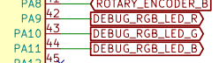
Microcontroller Pins:
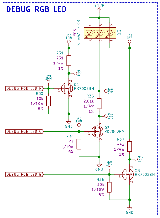
Debug RGB LED:
I wrote functions for each LED for Turn On and Turn Off. I included Red, Green, Blue and all other color combinations. This will make it easier to toggle these LED's once the code gets more complicated:
void TurnOnRedLED(void)
{
    HAL_GPIO_WritePin(GPIOA, GPIO_PIN_9, GPIO_PIN_SET);
    return;
}

void TurnOffRedLED(void)
{
    HAL_GPIO_WritePin(GPIOA, GPIO_PIN_9, GPIO_PIN_RESET);
    return;
}

void TurnOnGreenLED(void)
{
    HAL_GPIO_WritePin(GPIOA, GPIO_PIN_10, GPIO_PIN_SET);
    return;
}

void TurnOffGreenLED(void)
{
    HAL_GPIO_WritePin(GPIOA, GPIO_PIN_10, GPIO_PIN_RESET);
    return;
}

void TurnOnBlueLED(void)
{
    HAL_GPIO_WritePin(GPIOA, GPIO_PIN_11, GPIO_PIN_SET);
    return;
}

void TurnOffBlueLED(void)
{
    HAL_GPIO_WritePin(GPIOA, GPIO_PIN_11, GPIO_PIN_RESET);
    return;
}

void TurnOnYellowLED(void)
{
    HAL_GPIO_WritePin(GPIOA, GPIO_PIN_9, GPIO_PIN_SET);
    HAL_GPIO_WritePin(GPIOA, GPIO_PIN_10, GPIO_PIN_SET);
    return;
}

void TurnOffYellowLED(void)
{
    HAL_GPIO_WritePin(GPIOA, GPIO_PIN_9, GPIO_PIN_RESET);
    HAL_GPIO_WritePin(GPIOA, GPIO_PIN_10, GPIO_PIN_RESET);
    return;
}

void TurnOnPurpleLED(void)
{
    HAL_GPIO_WritePin(GPIOA, GPIO_PIN_9, GPIO_PIN_SET);
    HAL_GPIO_WritePin(GPIOA, GPIO_PIN_11, GPIO_PIN_SET);
    return;
}

void TurnOffPurpleLED(void)
{
    HAL_GPIO_WritePin(GPIOA, GPIO_PIN_9, GPIO_PIN_RESET);
    HAL_GPIO_WritePin(GPIOA, GPIO_PIN_11, GPIO_PIN_RESET);
    return;
}

void TurnOnCyanLED(void)
{
    HAL_GPIO_WritePin(GPIOA, GPIO_PIN_10, GPIO_PIN_SET);
    HAL_GPIO_WritePin(GPIOA, GPIO_PIN_11, GPIO_PIN_SET);
    return;
}

void TurnOffCyanLED(void)
{
    HAL_GPIO_WritePin(GPIOA, GPIO_PIN_10, GPIO_PIN_RESET);
    HAL_GPIO_WritePin(GPIOA, GPIO_PIN_11, GPIO_PIN_RESET);
    return;
}
I added some simple code in the main while loops to test each function:
  while (1)
  {
      TurnOnRedLED();
      HAL_Delay(1000);
      TurnOffRedLED();
      HAL_Delay(1000);

      TurnOnGreenLED();
      HAL_Delay(1000);
      TurnOffGreenLED();
      HAL_Delay(1000);

      TurnOnBlueLED();
      HAL_Delay(1000);
      TurnOffBlueLED();
      HAL_Delay(1000);

      TurnOnYellowLED();
      HAL_Delay(1000);
      TurnOffYellowLED();
      HAL_Delay(1000);

      TurnOnPurpleLED();
      HAL_Delay(1000);
      TurnOffPurpleLED();
      HAL_Delay(1000);

      TurnOnCyanLED();
      HAL_Delay(1000);
      TurnOffCyanLED();
      HAL_Delay(1000);
  }
I then compiled and loaded this code to the micro and tested the SW:
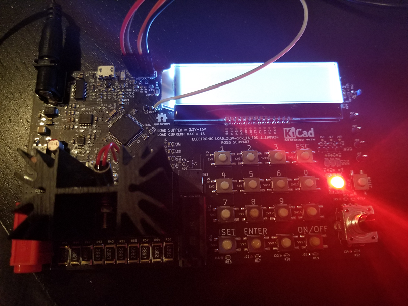
Red:
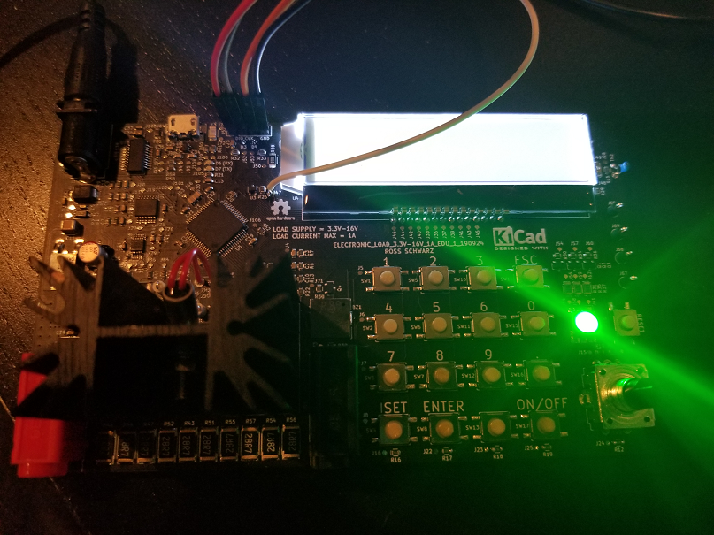
Green:
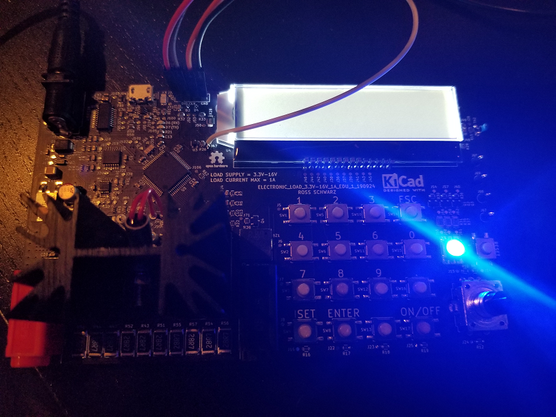
Blue:
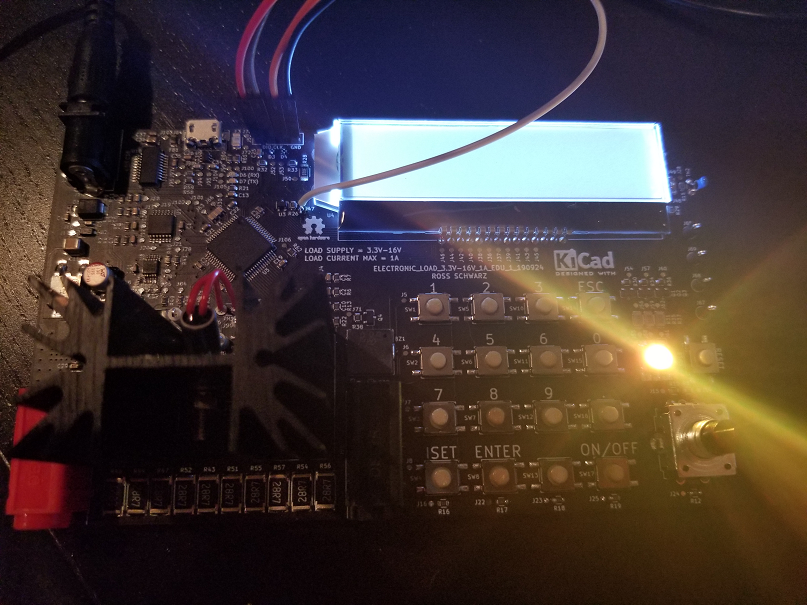
Yellow:
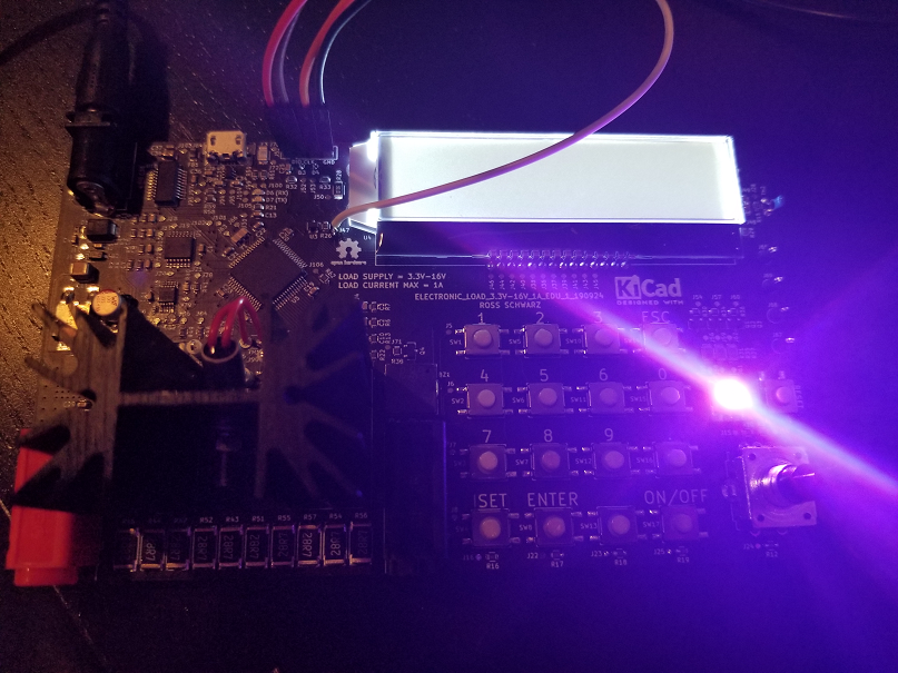
Purple:
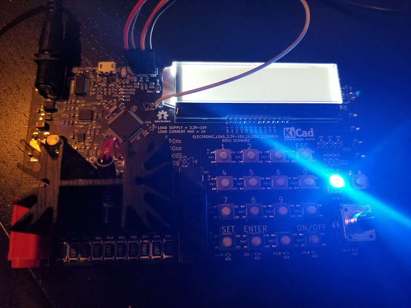
Cyan:
-
Getting To Ready To Code
12/12/2019 at 00:34 • 0 commentsGetting started with the software portion of the project proved to be quite difficult. I had to learn which tools and software to use in order to do so. Below is a breakdown of my selections along with how you can get started yourself if you wish to use a similar tool chain.
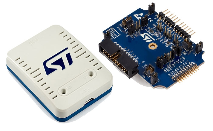
Programming Tool:
I chose the STLINK-V3
https://www.st.com/en/development-tools/stlink-v3set.html
This seems to be a very versitile tool. I plan on using the following pins to interface with my board:
- VCC (3.3V)
- CLK
- GND
- DIO
- NRST (Forgot to route, going to need to solder wire to make connection [TP 47])
Choosing an IDE:
Choosing an IDE seemed to be the most difficult decision. Through a bit of research I decided on using the following tools:
- STM32CubeIDE
- This is where I will be writing my code
- https://www.st.com/en/development-tools/stm32cubeide.html
- STM32CubeMX
- This is used to autogenerate the code for hardware specific portions of the SW
- Pin assignments
- Clock settings
- etc.
- This is used to autogenerate the code for hardware specific portions of the SW
- STM32CubeProgrammer
- This is used to take the binary file generated from the IDE and flash it to the microcontroller
- https://www.st.com/en/development-tools/stm32cubeprog.html
Powering Board:
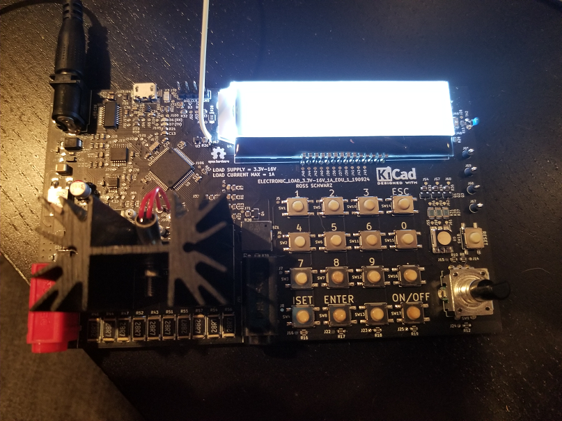
I simply plugged in a 12V center positive plug pack into the power connector. You could power up using a current limited supply just in case, but I felt confident so I plugged directly into wall.
You should see the back light on LCD power on:
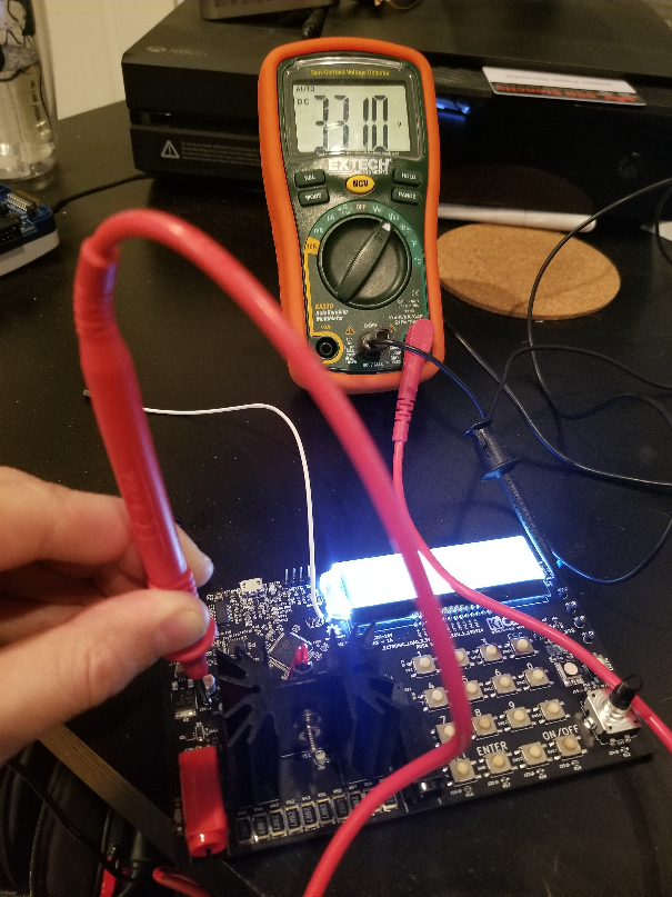
You should also be able to measure 3.3V on the voltage regulator:
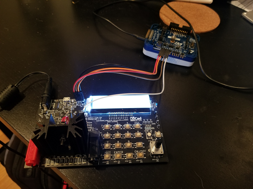
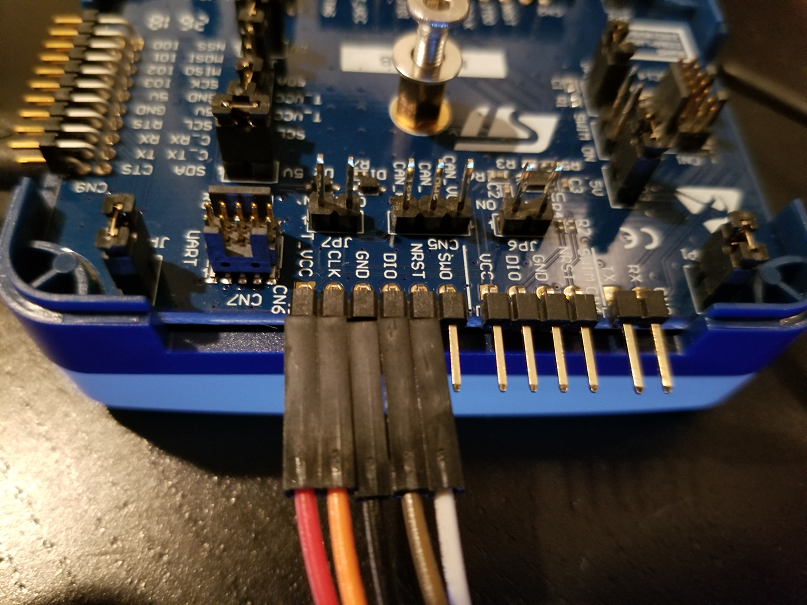
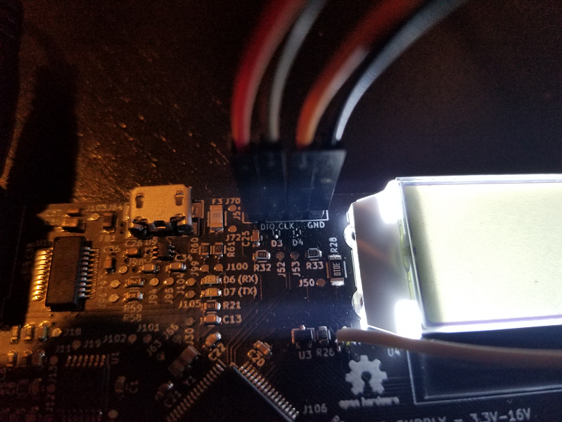
Connecting Board To Programming Tool:
Next I connected the programming tool to my board. You will need to make the following connections:
- VCC (3.3V)
- CLK
- GND
- DIO
- NRST (Forgot to route, going to need to solder wire to make connection [TP47])
I plan on switching to the STLINK-V3 main 14 way connector for future revisions in order to simplify the programming tool connections.
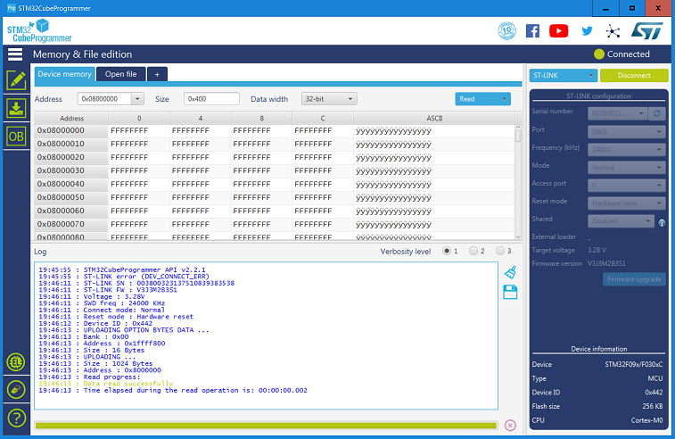
Communicating With Microcontroller:
With everything plugged in. I opened the STM32CubeProgrammer, crossed my fingers and hit connect:
I succesfully connected to the microcontroller which means I am ready to start programming.
-
Electronic Load 3.3V-16V 1A EDU 1 Release
12/01/2019 at 19:30 • 0 commentsUploaded Electronic Load 3.3V-16V 1A EDU 1 files and updated all relevant material to reflect this latest revision.
Electronic Load 3.3V-16V 1A
Electronic load that supports 3.3V-16V at 1A of current. Equipped with keypad, LCD, rotary encoder, STM32 Microcontroller and more!