-
1Sound Check
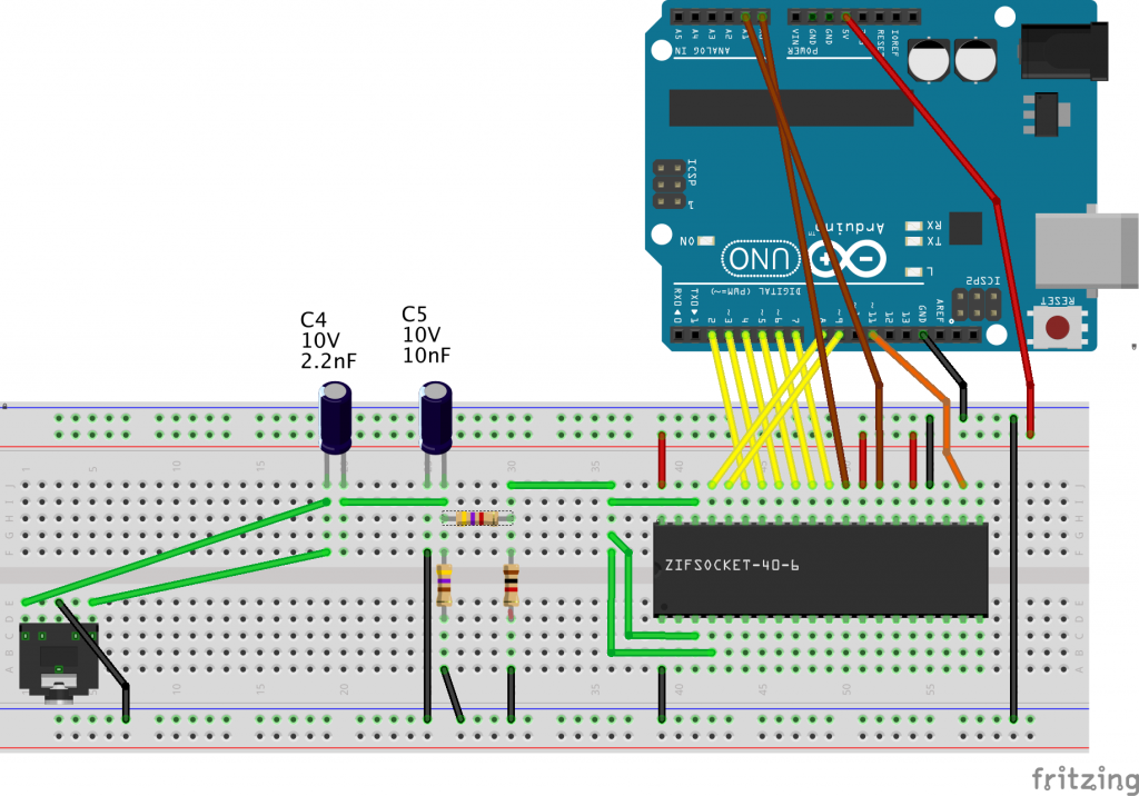
This is the quick hack of another code sample "Register writer" to play a warm up sound. The hardware is based on the schematic linked in the code. Works with Arduino Uno R3 aka: 328 compatible boards.
https://pastebin.com/raw/FehmVLQS
/******************************************************************* * AY-3-3910 Register writer for Arduino * (c) 2014 Manoel "Godzil" Trapier * * All the code is made by me apart from the the timer code that * was inspired from code found on the internet. I'm sorry, I can't * remmember where. **************************** Licence ****************************** * This file is licenced under the licence: * WTFPL v2 Postal Card Edition: * * DO WHAT THE FUCK YOU WANT TO PUBLIC LICENSE * Version 2, December 2004 * * Copyright (C) 2004 Sam Hocevar * * Everyone is permitted to copy and distribute verbatim or modified * copies of this license document, and changing it is allowed as long * as the name is changed. * * DO WHAT THE FUCK YOU WANT TO PUBLIC LICENSE * TERMS AND CONDITIONS FOR COPYING, DISTRIBUTION AND MODIFICATION * * 0. You just DO WHAT THE FUCK YOU WANT TO. * 1. If you like this software you can send me a (virtual) postals * card. Details bellow: * * < godzil-nospambot at godzil dot net > * * If you want to send a real postal card, send me an email, I'll * give you my address. Of course remove the -nospambot from my * e-mail address. * ******************************************************************/ /* * mod xBeau 1/22/2020 * Wiring: * https://www.986-studio.com/wp-content/uploads/2015/05/AY-3-8910_Arduino_bb-1024x716.png */ const int freqOutputPin = 11; // OC2A output pin for ATmega328 boards // Constants are computed at compile time // If you change the prescale value, it affects CS22, CS21, and CS20 // For a given prescale value, the eight-bit number that you // load into OCR2A determines the frequency according to the // following formulas: // // With no prescaling, an ocr2val of 3 causes the output pin to // toggle the value every four CPU clock cycles. That is, the // period is equal to eight slock cycles. // // With F_CPU = 16 MHz, the result is 2 MHz. // // Note that the prescale value is just for printing; changing it here // does not change the clock division ratio for the timer! To change // the timer prescale division, use different bits for CS22:0 below const int ocr2aval = 3; // The following are scaled for convenient printing // void setup_clock() { pinMode(freqOutputPin, OUTPUT); // Set Timer 2 CTC mode with no prescaling. OC2A toggles on compare match // // WGM22:0 = 010: CTC Mode, toggle OC // WGM2 bits 1 and 0 are in TCCR2A, // WGM2 bit 2 is in TCCR2B // COM2A0 sets OC2A (arduino pin 11 on Uno or Duemilanove) to toggle on compare match // TCCR2A = ((1 << WGM21) | (1 << COM2A0)); // Set Timer 2 No prescaling (i.e. prescale division = 1) // // CS22:0 = 001: Use CPU clock with no prescaling // CS2 bits 2:0 are all in TCCR2B TCCR2B = (1 << CS20); // Make sure Compare-match register A interrupt for timer2 is disabled TIMSK2 = 0; // This value determines the output frequency OCR2A = ocr2aval; } enum { INACTIVE = B00, READ = B01, WRITE = B10, ADDRESS = B11}; void setup_data(int mode) { switch(mode) { default: case READ: case INACTIVE: DDRD = B00000000; // Set all D port as input DDRB &= ~0x03; break; case ADDRESS: case WRITE: DDRD = B11111111; // Set all D port as output DDRB |= 0x03; break; } } void setup_control() { DDRC = DDRC | B00000011; PORTC &= ~B00000011; } void set_control(int mode) { PORTC = (PORTC & 111111100) | (mode); } void SetData(unsigned char data) { PORTD = data & 0xFC; PORTB = data & 0x03; } unsigned char GetData(void) { return (PORTD & 0xFC) | (PORTB & 0x03); } /* Registers */ enum { REG_FREQ_A_LO = 0, REG_FREQ_A_HI, REG_FREQ_B_LO, REG_FREQ_B_HI, REG_FREQ_C_LO, REG_FREQ_C_HI, REG_FREQ_NOISE, REG_IO_MIXER, REG_LVL_A, REG_LVL_B, REG_LVL_C, REG_FREQ_ENV_LO, REG_FREQ_ENV_HI, REG_ENV_SHAPE, REG_IOA, REG_IOB }; void write_2149_reg(uint8_t reg, uint8_t value) { setup_data(ADDRESS); SetData(reg & 0x0F); set_control(ADDRESS); delayMicroseconds(3); set_control(INACTIVE); delayMicroseconds(1); setup_data(WRITE); SetData(value); delayMicroseconds(1); set_control(WRITE); delayMicroseconds(5); set_control(INACTIVE); PORTD = 0; //setup_data(INACTIVE); } uint8_t read_2149_reg(uint8_t reg) { uint8_t ret = 0; return ret; } char regs[14]; int j; void setup() { setup_clock(); setup_control(); setup_data(INACTIVE); Serial.begin(115200); // Be sure to kill all possible sound by setting volume to zero write_2149_reg(REG_LVL_A, B00000000); write_2149_reg(REG_LVL_B, B00000000); write_2149_reg(REG_LVL_C, B00000000); j = 0; Serial.println("init"); delay(500); Serial.println("test"); write_2149_reg(REG_LVL_A, B00001111); write_2149_reg(REG_FREQ_A_HI, B00000010); delay(250); write_2149_reg(REG_FREQ_A_HI, B00000001); delay(250); write_2149_reg(REG_FREQ_A_HI, B00000100); delay(250); write_2149_reg(REG_FREQ_A_HI, B00000110); delay(500); Serial.println("ALL OFF"); write_2149_reg(REG_LVL_A, B00000000); write_2149_reg(REG_LVL_B, B00000000); write_2149_reg(REG_LVL_C, B00000000); } void loop() { int i; while (Serial.readBytes(regs, 14) != 14); for(i = 0; i < 14; i++) { write_2149_reg(i, regs[i]); } } -
2Breadboard Arduino Test
Wire hardware as follows, note that C5 was omitted and bypassed in testing and sample recordings.
![]() Image Source (986-studio.com)
Image Source (986-studio.com)
 xBeau
xBeau
Discussions
Become a Hackaday.io Member
Create an account to leave a comment. Already have an account? Log In.