Ahron Wayne
-
1906 indian head stack + stitch
05/20/2020 at 02:41 • 0 commentsDad gives coin, coin goes on scanner, pictures get taken, pictures get stacked, stacks get stitched. Easy peezy.
![]()
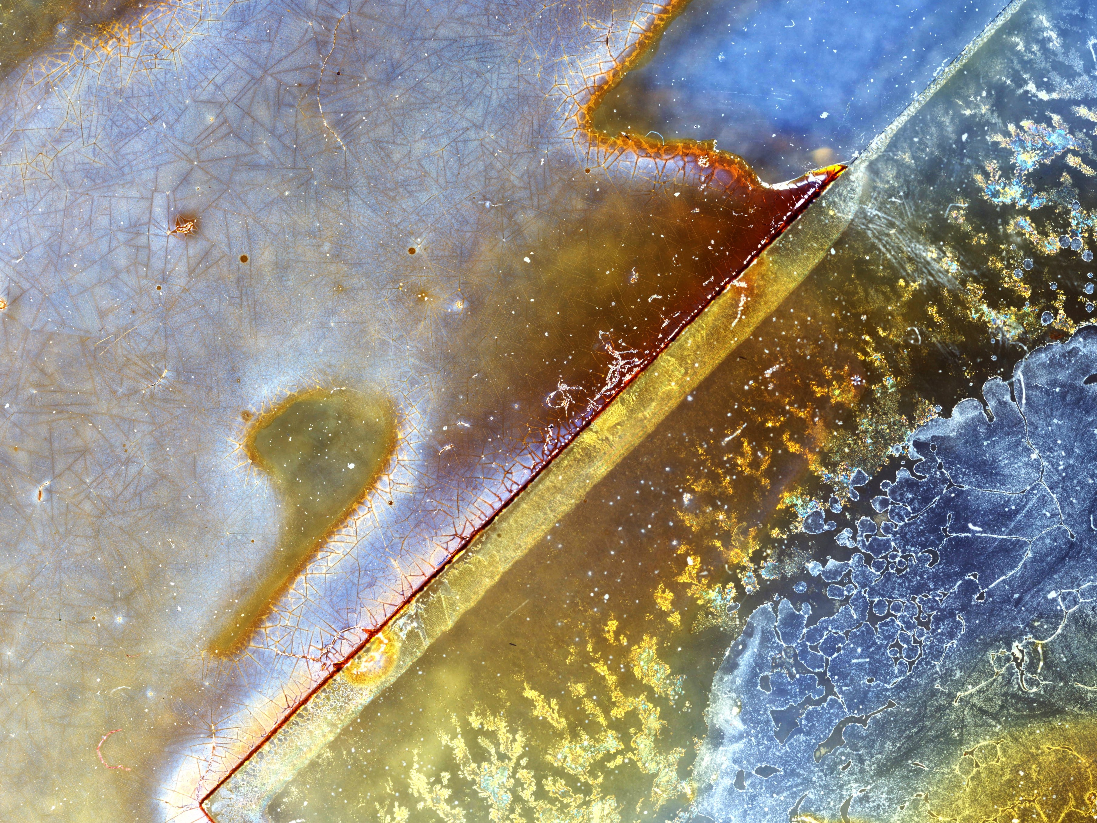
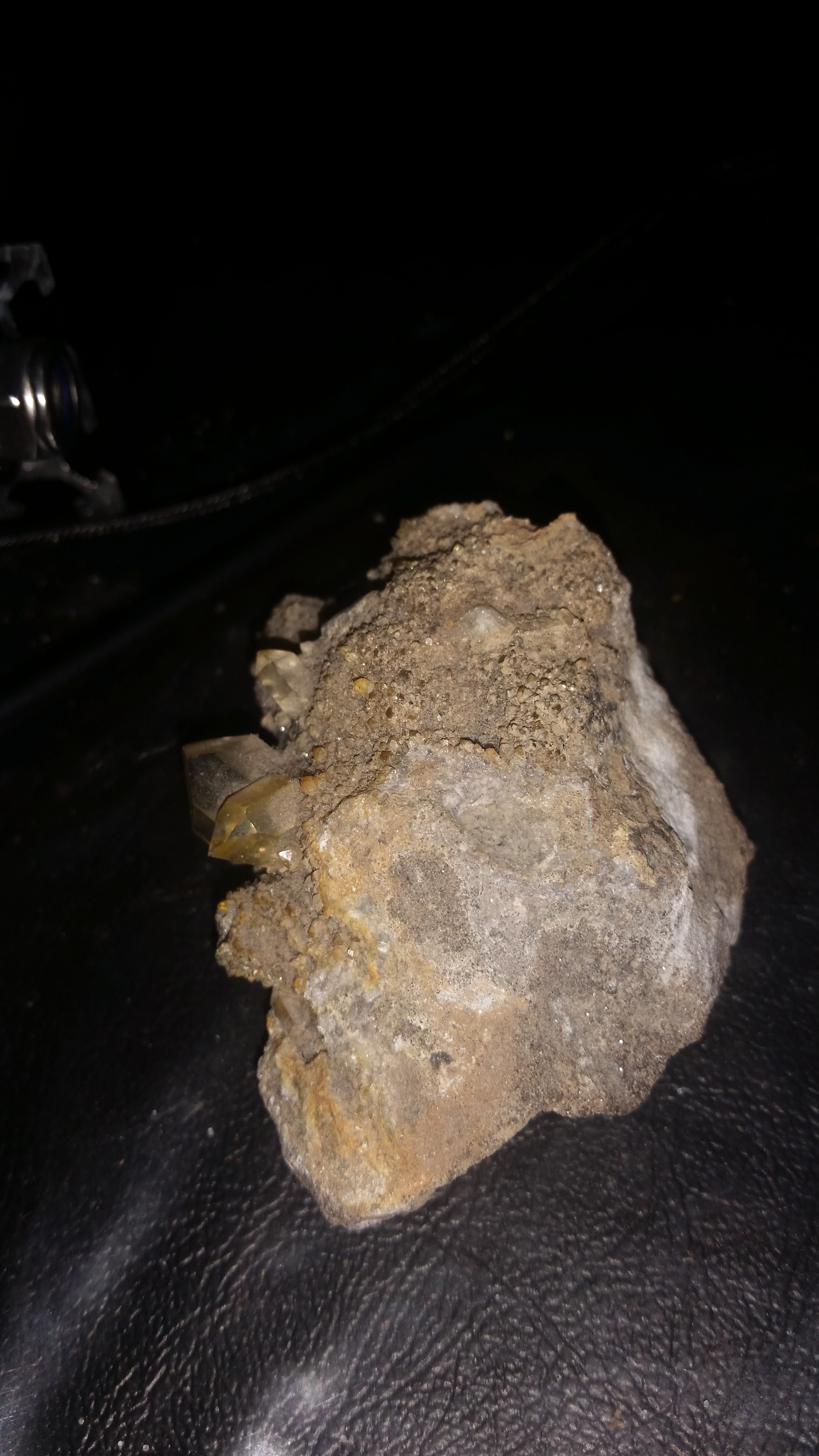
This here is an excellent application of stack+stitch. The leaf is just way too big for my capabilities, with too many Z heights (16?) and too large in breadth (11,515). Our 114 year old coin here in comparison is just 500 in breadth and 3 in height, and I even stretched that out a bit by going for 0.15 mm steps instead of 0.1 mm ("Wowee").
The final image is 40 megapixels or so and is pretty packed with information in my opinion. You can tell that this coin has lived a full life.
-
Old crusty Iodine
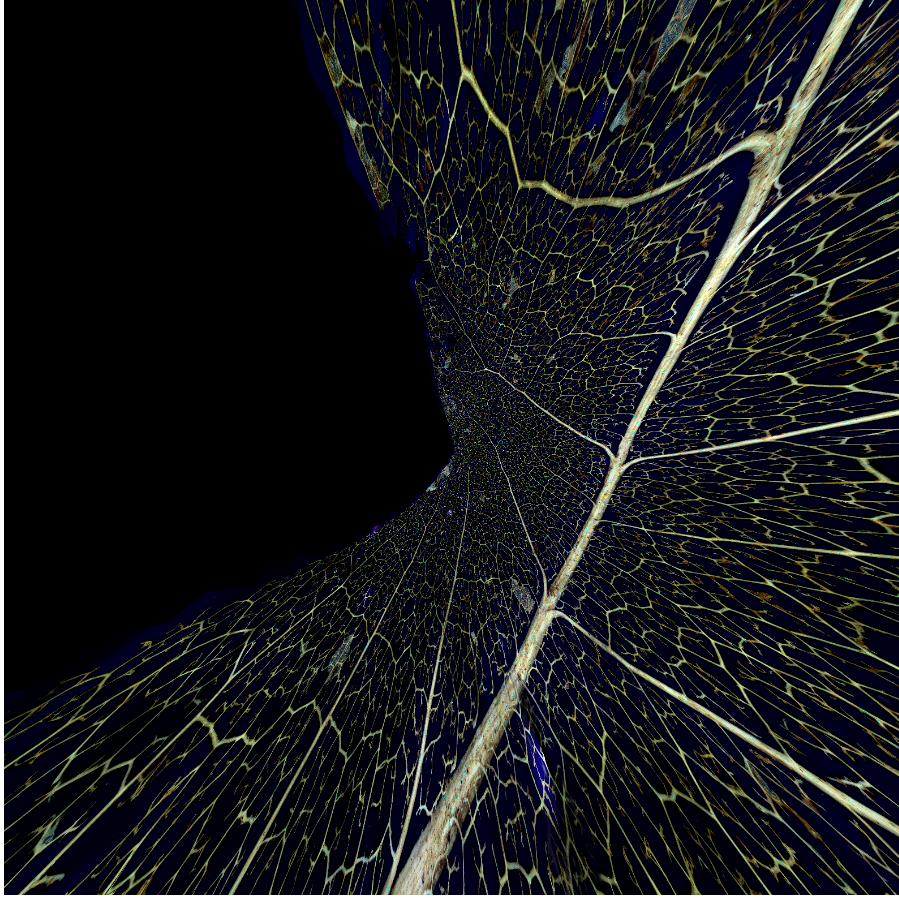
05/11/2020 at 21:23 • 0 commentsI have spent a solid month trying to turn 166,675 pictures of a leaf into one picture of a leaf. I regret to say that I have not yet succeeded for a variety of reasons involving ram, Microsoft cloud computing, and the GoPro corporation. Does this look like a leaf to you?
![]()
I am still hopeful that I will succeed, on account of all the data existing in a regular ordered grid and I would be happy with a solution that just smushed them together without trying to account for perspective shifts and focal lengths, which almost all panorama software insanely has the obligation to do for some reason.
Meanwhile, yesterday I had an old dish of iodine disinfectant, so I put it on the build plate and then set the scan going while in bed without actually looking at what I was doing. About 400 pics, I think it turned out neat!
![]()
-
A really huge picture of a leaf (part 1)
04/22/2020 at 22:24 • 0 commentsOver the last week, I took 165,675 pictures of a leaf.
It was a skeleton of a leaf. I found it in my backyard. I wet it, placed it in newspaper, and left it under a heavy weight for weeks to flatten it.
I removed it, placed it under some glass that I had carefully cleaned and blow dried, and clipped it onto a microscope stage to assure it would be stable.
I set the parameters of the scan. It said it would be 200,005 pictures. That was too much, so I scaled the scan back a bit.
I started the scan to run overnight. At four AM I came downstairs and noticed that the scan had stopped after a mere twenty thousand pictures. That was odd. What could it be? I started to troubleshoot the scan, then just restarted it around where it had left off. I came back in the morning to find it had failed, again. USB disconnects, still can't figure out why.
I reworked my program to rehome and restart whenever it encountered a disconnect. Not ideal, but good enough for now. I let it run. Ten restarts and 15 hours later, it was done: 165,675 pictures.
Then I had to remove the useless black (not over my leaf) pictures. And change the file structure for the stacking and stitching programs to handle. Then stack eleven thousand one hundred and fifteen sets of images before they could be stitched together. My computer can do about 20 a minute.
That's where I am now. I wanted to tell you before I showed you the actual picture, because I am hoping it will be glorious, and complaining is not glorious.
So sorry that there's no picture, but in the meantime, maybe you'll enjoy this video from my latest project, utilizing the same hardware as this one:
-
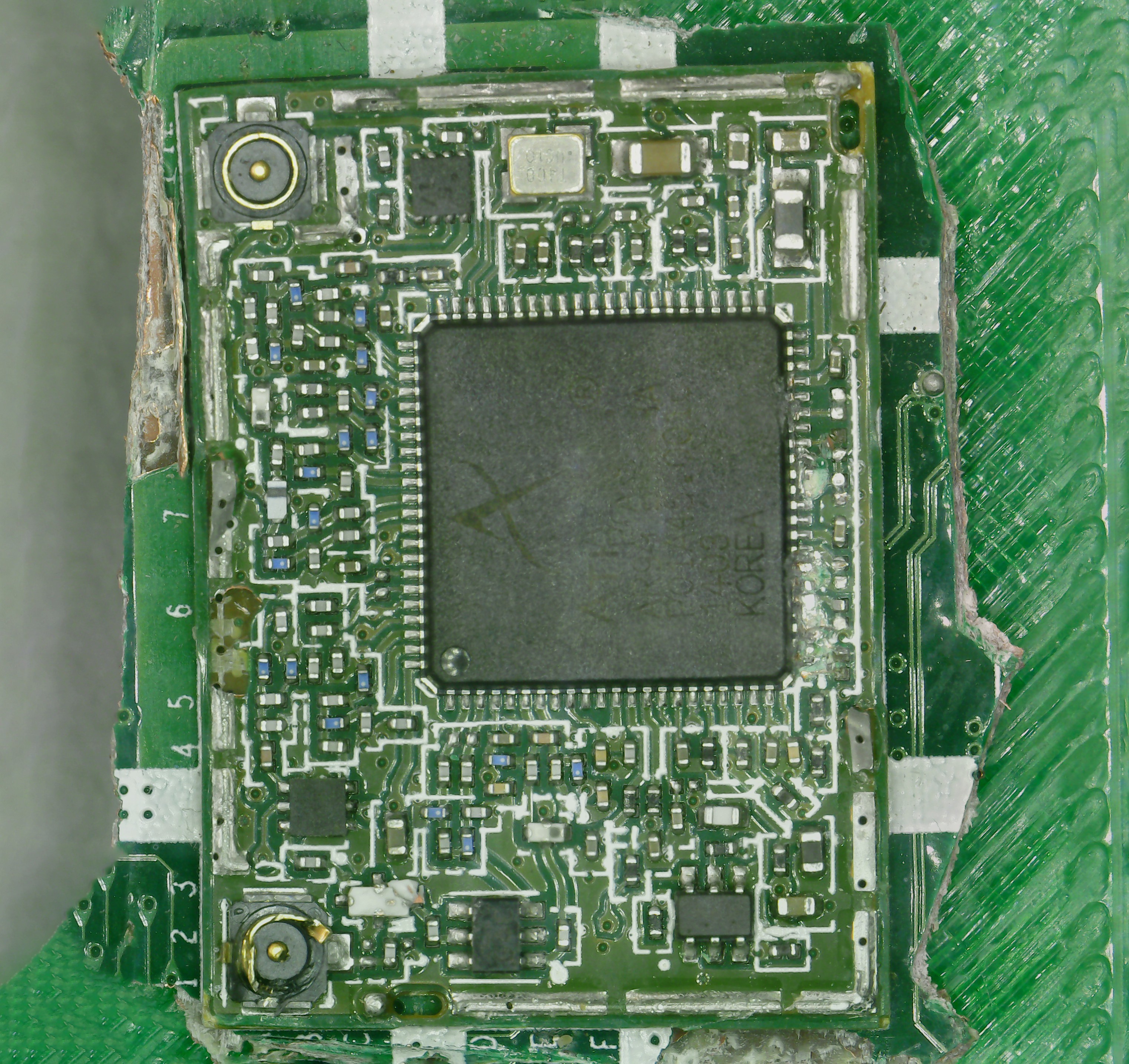
PCB Scans (with stitching)
04/13/2020 at 16:18 • 0 commentsI took a couple of PCB scans with the old setup using cheapo USB microscopes. I didn't include them, though. Why? Because the final image was noticably warped:
![]()
Again, the above is with a 12 dollar usb microscope, so you're not expecting it to be perfect --- but the warping makes it obvious that it came about by stitching. The same problem occurs to some degree with all objects, but is most apparent for rectangular ones. Usually I just crop them out strategically to provide a dishonest representation of how good they were to begin with.
But the cause of the warping was a matter of debate --- how much was due to the 12 dollar camera and how much due to the software? A new scan sheds light on the problem:
![]()
Still not perfect, but quite noticeably better. 77 pictures with the scan itself taking 30 seconds. It turns out at least some of the warp is due to the camera, not the stitcher, even if you don't notice the warp on the individual pictures (I certainly don't). This also gives hope for some software solution if you can figure out exactly how much warp the camera is inducing and where.
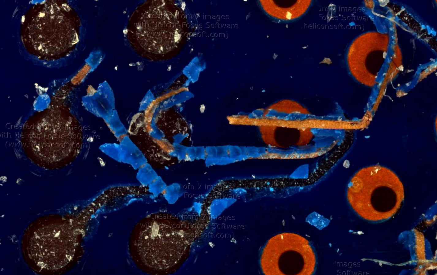
That patch on the left side is where I pried up an onboard chip to provide a good area for a high res scan. I prepared it for a photogrammetry/photography superhero from facebook so he could try stacking with stitching for eventual 3D model generation efforts. Here is one set of 165 stitched pictures from a single Z height.![]()
Decent stitch again, but with parts in and out of focus in the same frame (mixing and matching images isn't going to work the best here). That's why I took the same scan from 7 Z heights 0.1 mm apart, which enabled me to finally do something I've been meaning to for a while --- combine stacking and stitching. And it worked great!
![]()
...until you look too closely and see, as with much of my work, the glue which holds it together:
I wonder which program I used the trial version of to do the stacking? Frankly I'm astonished that the watermarks didn't impact the the stitching process notably, like, at all.
I'd last like to add that theoretically, we have all the data now to create some kind of 3D rendering. Is it going to be 100 percent spot-on? No. Is it going to look decent enough? Perhaps. It depends on the application you are working with. The expert I consulted said that the programs demand accuracy to within a pixel, and would be seriously turned off by the x/y stitching process. In addition, expert was unable to "solve" the error profile for the lens used to take the pictures, which is part of the process in getting that sub-pixel accuracy. If you could solve the lens, maybe it would even improve the final quality of our cheapo 12 dollar microscopes.
So there's your PCB images. And I still have all the data from this scan, so I'm hoping that one day it will be turned into that 3D model after all. Stay tuned! -
Automated PCB inspection
04/10/2020 at 01:43 • 0 commentsSo I got distracted for a couple of days from the whole Z stacking thing to create a this-will-break-if-anything-changes demonstration of the potential for automated PCB inspection.
It's actually scanning the version 1 board for the original DIY (blu ray players) ladybug, and which has way too much stuff on it (it was my first and so far only board made mostly by myself). Basically, all this program does is take a csv file generated by EasyEDA for pick and place machines, organize the important bits, does some basic math and cleanup on like the units for the component locations, and provides a rudimentary interface for interacting with the information and taking pictures.
One thing that got added to the rest of the program was a "find shortest path between a list of coordinates" function, which it turns out is the hardest problem in all my code computationally (it's the NP complete traveling salesman). I just grabbed the first ready-made python module for it, but still. Finding the path for the points shown in the video above took as long as the scan itself --- clearly not ideal. Definitely need a faster solution with some tolerance allowed if this would ever be used on thousands of points or more.
The idea for this kind of thing is straightforward enough, but it all really depends on how it's implemented. And my implementation is Not Good, at least for the amount of time it took me. Even apart from the major lack of a user interface, it would just never survive an environment with changing demands and requirements, at least not without constant upkeep (by me). My formal CS background is six weeks of python in a summer semester --- and I feel like that's really leaking through, at least judging by the number of if-then statements in my code.
Oh, I mean, uh, hey! at least it works...?!
-
Focus stacking (kinda)
04/07/2020 at 01:51 • 0 commentsTeam member Yujie is quarantined, too. This has left him weak and prone to suggestions, like "instead of doing your homework, can you implement this very specific form of focus stacking to prove a point about focus stacking?".
Say you have a lumpy object like this rock:
![]()
That certainly is lumpy. Even if you were to mix and max images at different Z heights, you would still have a problem --- there would be spots within each image that were out of focus. That method does alright if you have a gentle, sloping image, but is clearly not going to fly here. You need 15 images (1 mm apart) to cover the whole field.
![]()
I said last time that the ideal thing to do would be to physically point scan each pixel and combine them in 2D. And again, that's basically what focus stacking is --- you align the images and just pick out the best pixels from each one. But after I thought about fields of view and such for way too long, what I wanted to see was what if you just trended towards this, by matching focuses in chunks of more than a pixel:
![]()
We start out with a block of 1, which is just the image that was best in focus, and end in blocks of 20 pixels on a side. The changes are dramatic and choppy at first, but then we get into a rhythm and things just get smoother and more properly contoured and MM! Wow!
There are some flaws with this. One is that the code makes us lose pixels sometimes which causes everything to wibble or even weirder with smaller block sizes, like so:![]()
Another is that the field of view changes towards the edge a bit as the camera moves, even though we are not changing our focal point (something that I did not account for, and which can be fixed by image alignment).
But fundamentally it actually works exactly as it's supposed to. Reinventing the wheel of course, but I think this insight into what stacking really is will end up being useful. The goal with stacking, by the way, beyond getting better images, is to also use the depth-from-focus information gained to make depth maps and 3D models. -
it's not all perfect though
04/03/2020 at 23:19 • 0 commentsNot everything works exactly as I'd like it to.
First, here's a bit of a bizarre bug I encountered while getting ready to scan my phone screen, which I last did using the original ladybug:
Whoops, I guess this turns out to be impossible. I wish I had some concrete explanation for why this occurred --- I can get a very fuzzy idea why, but it breaks down if I think about it too hard. Like, could this be used for the world's worst autoleveling feature, by putting a phone at each corner of your build plate?
Next let's talk about the trade off of having a larger field of view at the same magnification, with this very helpful drawing:If you have a larger field of view at the same depth of focus, it is more likely for parts of the image to be out-of-focus. Confocal microscopes like DVD players solve this by doing point scanning --- each bit of information or pixel if you will is obtained separately, with focus controlled using a servo feedback loop. To take a picture of the whole disk all at once and resolve all the information would require disgustingly perfect widefield optics and a perfectly flat field.
The same goes for us. It's not just that scanning this way can get around having a limited field of view, it's that having a limited field of view is essential for it to work in the first place. If all you're doing is mixing and matching pictures, then for the whole thing to be in focus at the end of it, all of the little pictures have to be in focus, too --- and the smaller each little picture's field of view is, the more likely that is to happen.
Except. What happens if you fake it? What if you take your wider field-of-view image at many Z heights and artificially split them up into sections? Then you can mix and match the ones that are in focus, as if you had a smaller field of view to begin with! And it would make sense to extrapolate all the way down to the individual pixel, right?Well, congratulations, you've just invented image stacking. Let's try that next.
-
Everything is different now
03/25/2020 at 01:38 • 2 commentsImagine you're me: A broke grad student with dreams of turning his scanning microscopy hobby into something more. You scrimped and saved until you could afford old blu-ray players and a 12 dollar USB microscope, then sold plasma until you could upgrade to a broken 3D printer. You produced images that could always be described as "surprisingly good for being made of trash".
So then imagine you were offered the newest version of the only name brand USB microscope for free. How many microseconds would it to you to respond and go "yesyesyesomgplease"?
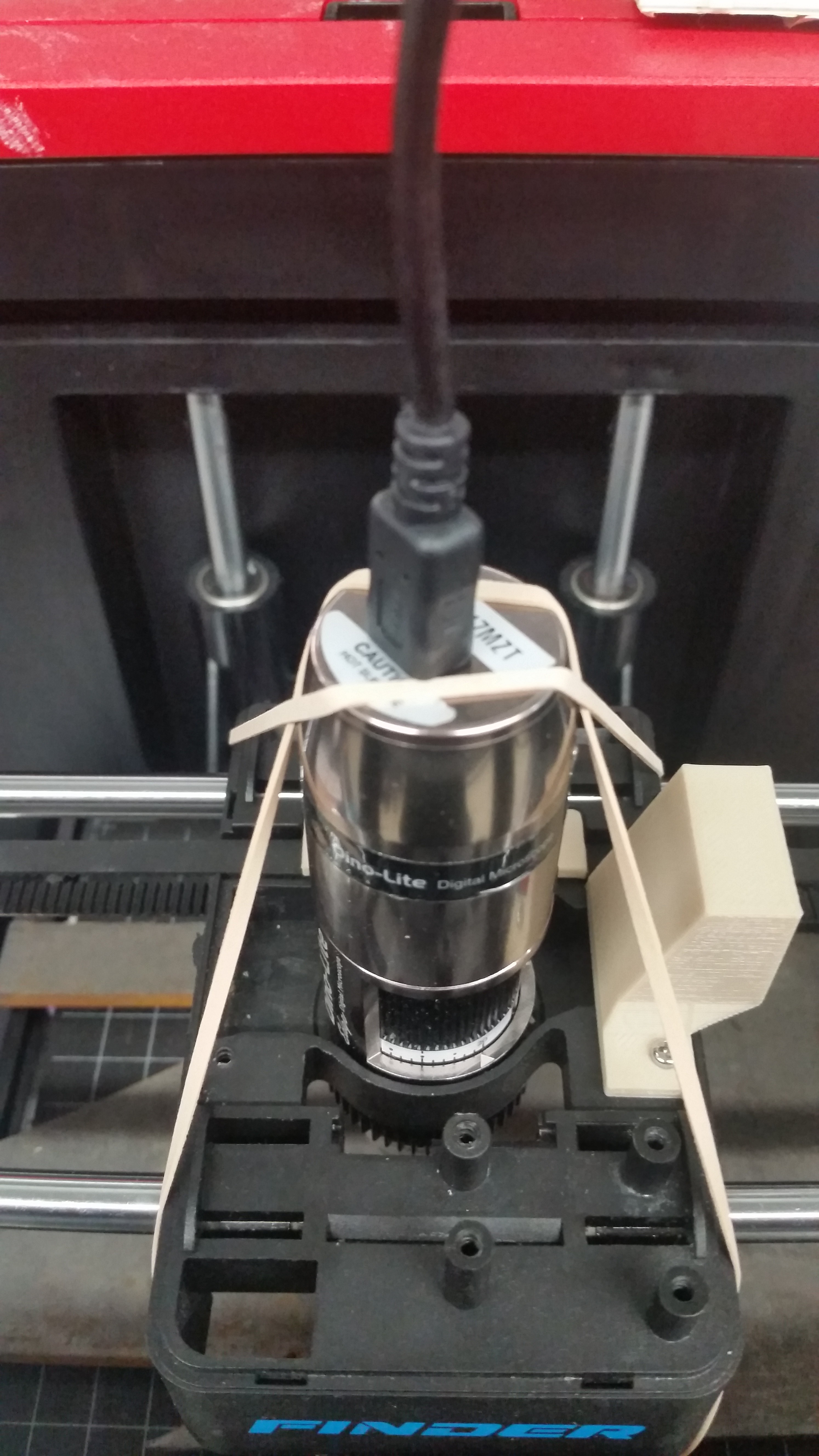
Of course the first thing you do is try to smoosh it into your current broken printer hole. You use a file (!) to cut away a few choice bits of material because the microscope has some pokey bits that get in the way. then, it turns out the plastic on the old one was actually helping it squeeze in and stay put, and aluminum just doesn't want to bend like that. So... straps?
![]()
I like stopgaps as much as the next guy, but this was starting to get ridiculous. Along with tons of dumb problems with the scope in the pi --- along with ahem, the coronavirus, a system I could work with from home (like on a laptop?) started sounding attractive.
So that's why everything is different now, because my 3D printer is now one that didn't start off with an exploded mainboard. One of these guys basically.
![tronxy_x1_tronxy-x1-3d-printer-review-the-facts-here-800x600.jpg (800×600)]()
Pros: bigger build plate while being less huge in general, solid metal frame, easy mounting points to the build plate. Con: The build plate moves in X axis, rather than just Z or none at all. This means you can't just plonk some objects on without fixation.
Anyway I have gcode control now and run it from a windows machine through pyserial! Getting it connected at all turned out to be the easiest process. Most of working with gcodes and such is just stringing, and then it is amazing to be able to just, for instance, home everything with a single line. Let the 3D printing nerds handle all the backend, like proper acceleration profiles --- I cannot believe I suffered this long listening to my system go kachunk kathunk kathunk for hours at a time. And then combine that with a much faster frame rate with a proper computer and open cv, and scans are at least three times faster now. Actually, twelve because the camera has four times the areal field of view without loss of pixel density! It really is fun to watch it go now.
Also I implemented a brute autofocus, which is basically what I was doing before after the scan but which you can now just do in real time.
And with all that I'd like to present the new system's first image, of a Canadian Toonie.
![]()
The scope has a polarized light knob which makes a HUGE difference for reflective surfaces like this. But beyond that, I was astonished at how normal the image looked. With just about any scan I've taken, I can find some flaw that gives it away --- a speckled pattern if you squint, mismatches and odd warping, a marked color gradient. This has almost none of that.
If you zoom in you'll spot some stuff --- mostly around the coinedge as a consequence of autofocus. But it turns out that a lot of what I complained of microsoft ICE was not really its fault --- it worked so hard, the poor thing! In the end, if you give it better images it begin with, it will reciprocate.
-
Inspection of Osseodensification drillbit
03/06/2020 at 01:08 • 0 commentsYesterday a professor beckoned me over and asked me if I wanted to drill into a pig's bones and give it a dental implant. Who wouldn't? Fun! I got to learn all about proper drilling technique, including that being too slow/timid can lead to literally burning the bone and causing lots of smoke.
This led to a discussion on the drill bit being used for the actual procedure. It turns out that they were invented by a dentist in my home state of Michigan, who discovered, rather serendipitously, that running a drillbit backwards in a pilot hole widens the bone by compacting it, rather than simply carving the material away. This leads to preservation of healthy bone and a better implant.
Cylindrical objects like drillbits are the perfect target for 3D imaging, so I figured I'd give it a try. It was only when I was in bed last night, having done one such scan, when I realized that, hey! I'm a biomedical engineering student, and this is the first first honest-to-goodness BME application I've used my scanner for!
So today I elected to do a relatively good job and put it all together in a video. Here it is after 10-12 hours! Enjoy?
LadyBug BEEFY: 3D printer motorized microscope
Got printer? Connect to the motors with a Pi, plonk in a cheap scope, and do 2D and 3D scans!