Adam Lange
-
Tutorial: Simple 5-axis surface milling
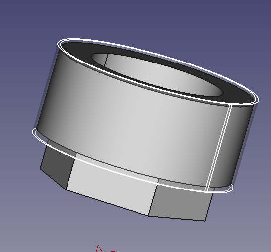
07/17/2020 at 16:58 • 1 commentThe example part is a nut for a high current, medium voltage, high pressure pass-through that will be machined on a 5-axis mill.
Yesterday I used FreeCAD's standard 'adaptive clearing and profiling' operation for all roughing. Here's the nut with the roughing toolpaths:![]()
To run this tutorial you will need to have OpenModelica, python-occ, and FreeCAD installed.
With the part roughed, now it's time make a 5-axis toolpaths for finishing the outside diameter. The outside diameter will be cut using a ball nose endmill and 5° incidence surface milling.
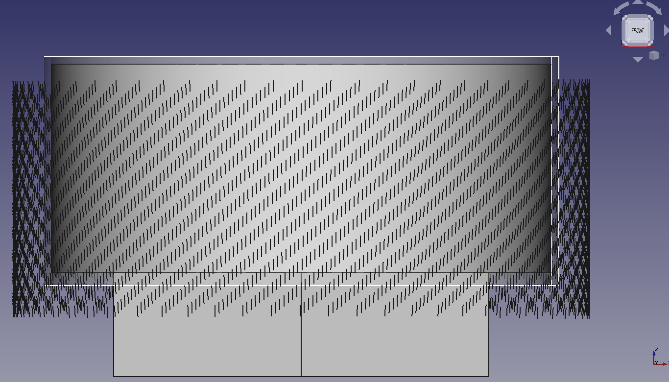
The first step in toolpath generation is to position the workpiece in FreeCAD exactly as the part is positioned on the milling machine.
Next I sketched and extruded some surfaces that are axially longer than the surface to be cut in the model. I'm making two cuts, one slightly over the finish diameter, and one at the finish diameter. There is a surface for each cut. I made the surfaces by extruding a sketch with the solid box unchecked.![]()
The surfaces need to be saved to individual brep files. I copied the extruded part and used Draft -> Downgrade, twice to get two face objects. I then exported each as a brep file.
The next step is to create tool targets based on these cylindrical faces. A tool target is two vectors, a tool tip position vector and a tool direction vector. I created a python module for creating tool targets from cylindrical surfaces. That module is included in the modelIKa repository: here. Today I will create a new script that loads the brep files and creates an instance of TurningToolpathGenerator which will be configured by setting class parameters and finally gcode will be created by invoking a method of the TurningToolpathGenerator.Launch OMEdit. Open modelIKa/IK/package.mo. The IK package will appear in the tree view on the left. Expand IK and double click on Machine. That will open a model of a 5 axis milling machine.
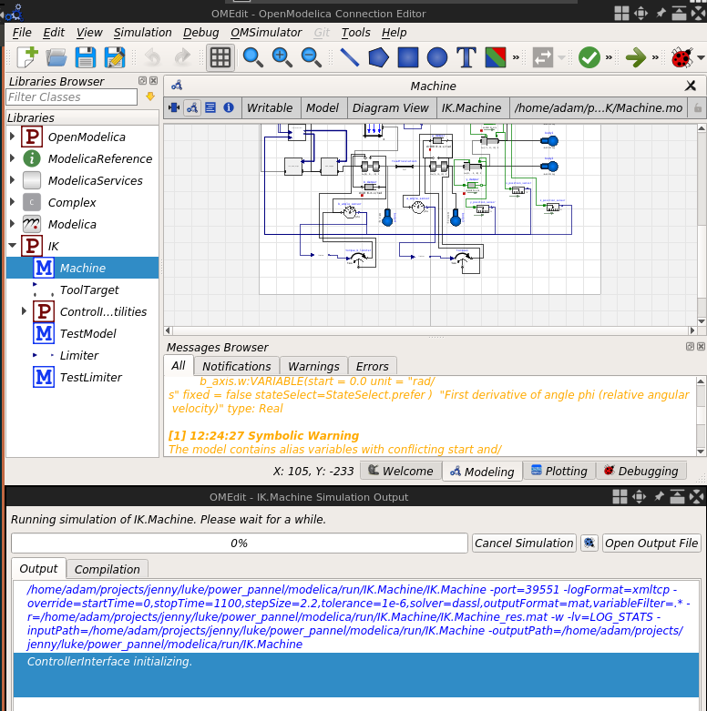
Next the simulation server needs to be started. Modelica simulation needs to be set up so that it will not complete before the client program is done requesting solutions. Go to Simulation -> Simulation Setup. A dialog will appear. Set "Stop Time" to 1000 seconds. Press "Ok". The simulation will launch but it won't progress because it is waiting for a connection from a client to request an inverse kinematics solution.
![]()
Next the client program needs to be launched. Open a terminal and go to modelIKa/python/toolpathGeneration/simple_5_axis_example. Two directories will need to by on the PYTHONPATH environment variable for the client script to execute successfully. Running the following commands will set up your PYTHONPATH environment variable.cd modelIKca/python/toolpathGeneration/simple_5_axis_example source python_path_setup.shNow the client script 'pass_1.py' can be run in the terminal where the setup script was executed. The client script will load one of the surfaces created in FreeCAD, analyze the surface, create tool tip targets, invoke the inverse kinematics solver for each tool tip target, and create gcode.
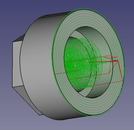
python3 pass_1.pyThe script, pass_1.py, will generate pass_1_targets.brep and pass_1.ngc. pass_1_targets.brep can be imported in FreeCAD to visualize the generated tool targets.
![]()
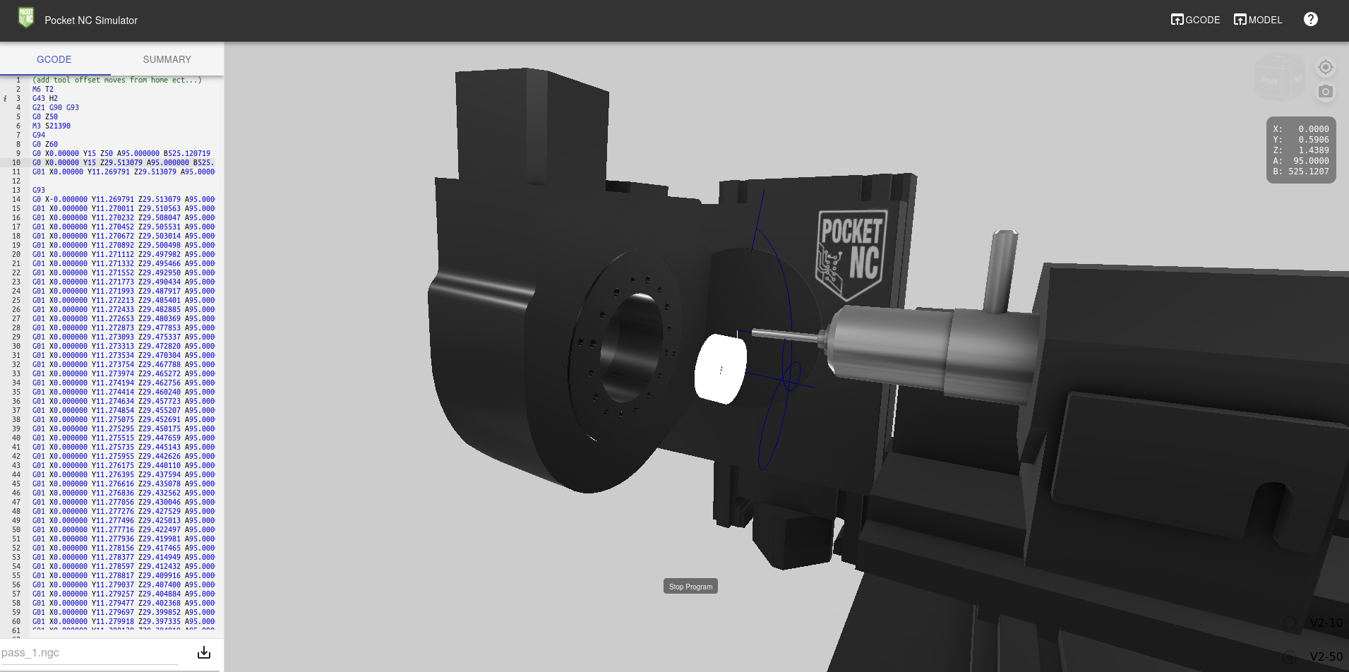
Warning! The gcode starts with a G0 move right into the part. Before I ran the code I added in a few lines of gcode by hand at the beginning to make the lead-in cut and a few lines in the end to retract. I then simulated the code using the PocketNC simulator: https://sim.pocketnc.com/ and finally proceeded to run the gcode on the machine.add tool offset moves from home ect...) M6 T2 G43 H2 G21 G90 G93 G0 Z50 M3 S21390 G94 G0 Z60 G0 X0.00000 Y15 Z50 A95.000000 B525.120719 (get clear) G0 X0.00000 Y15 Z29.513079 A95.000000 B525.120719 (Move to z) G01 X0.00000 Y11.269791 Z29.513079 A95.000000 B525.120719 F40 (lead-in cut) G93 G0 X-0.000000 Y11.269791 Z29.513079 A95.000000 B525.120719 G01 X0.000000 Y11.270011 Z29.510563 A95.000000 B530.843252 F324.124272 G01 X0.000000 Y11.270232 Z29.508047 A95.000000 B536.571001 F324.124272 G01 X0.000000 Y11.270452 Z29.505531 A95.000000 B542.298752 F324.124272 G01 X0.000000 Y11.270672 Z29.503014 A95.000000 B548.026501 F324.124272 G01 X0.000000 Y11.270892 Z29.500498 A95.000000 B553.754252 F324.124272 G01 X0.000000 Y11.271112 Z29.497982 A95.000000 B559.482002 F324.124272 ... G01 X0.000000 Y12.227163 Z18.570267 A95.000000 B25435.100473 F324.124272 G01 X0.000000 Y12.227383 Z18.567751 A95.000000 B25440.828223 F324.124272 G01 X0.000000 Y12.227604 Z18.565235 A95.000000 B25446.555973 F324.124272 G01 X0.000000 Y12.227824 Z18.562719 A95.000000 B25452.283723 F324.124272 G01 X0.000000 Y12.228044 Z18.560203 A95.000000 B25458.011473 F324.124272 G01 X0.000000 Y12.228264 Z18.557687 A95.000000 B25463.739223 F324.124272 G01 X0.000000 Y12.228484 Z18.555170 A95.000000 B25469.466973 F324.124272 G01 X0.000000 Y12.228504 Z18.554937 A95.000000 B25469.997391 F3498.633235 (add spindle stuff and return to home) G0 Y15 M5 G0 Z60 M2![]()
If you'd like to make the simulation a little more exciting, try offsetting or inclining the central axes of the cylindrical surfaces and repeating the g-code generation process. -
Boring accomplishments
02/19/2020 at 07:00 • 0 commentsToday I made a cut on my PocketNC 5-axis milling machine with gcode generated with the help of this inverse kinematics solver. I'd post a video of the cut if it wasn't boring. Literally boring. It was gcode to do finish passes on 1/8" diameter hole, with a ball nose endmill angled 5 degrees so that it was only cutting on the radius of the cutter, not the shank.
I'll have to do a more interesting cut.
-
Moving to multiple tool position targets in sequence
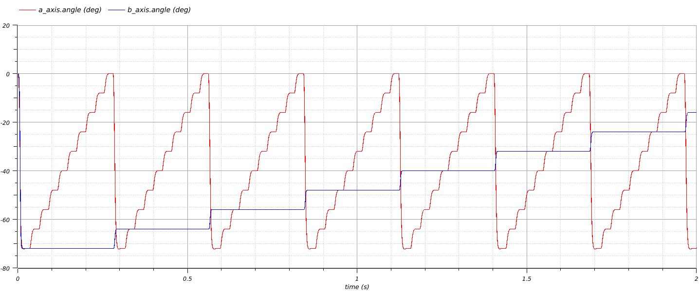
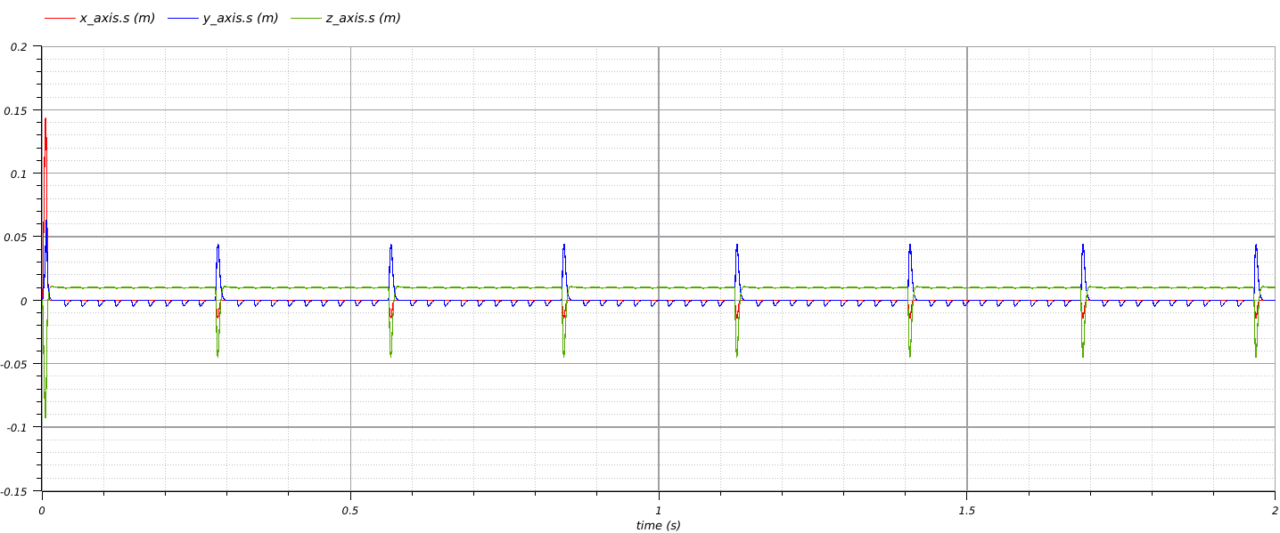
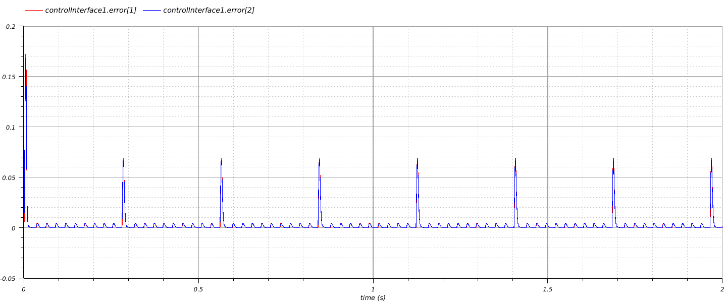
02/06/2020 at 20:41 • 0 commentsI created a modelica model that looks at the distance between the tool target and the actual position. Whenever the error is within a configurable tolerance the model records the current position of the machine joints and calls some external python code that reads new tool target positions from a file.
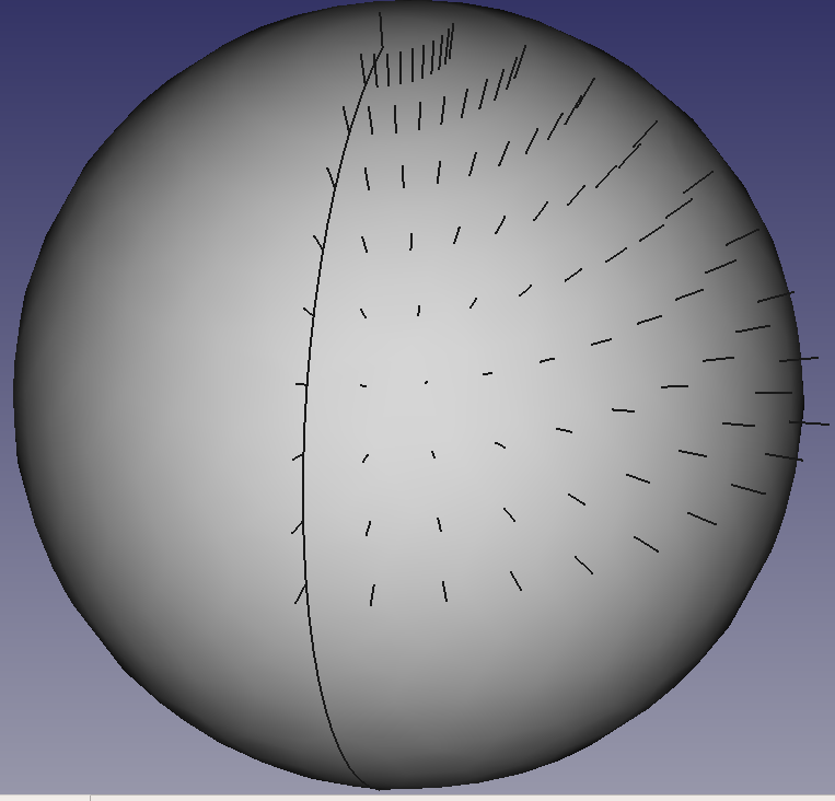
I created tool targets using pythonocc. I created a sphere. I accessed the position and normal vector of the sphere's surface at a few points and wrote those to a csv file in x,y,z,i,j,k format where x,y, and z are the position of the tool tip and i,j, k makes up a unit vector pointing from the tool tip back along the cutting tool axis. This is what the target points look like:
![]()
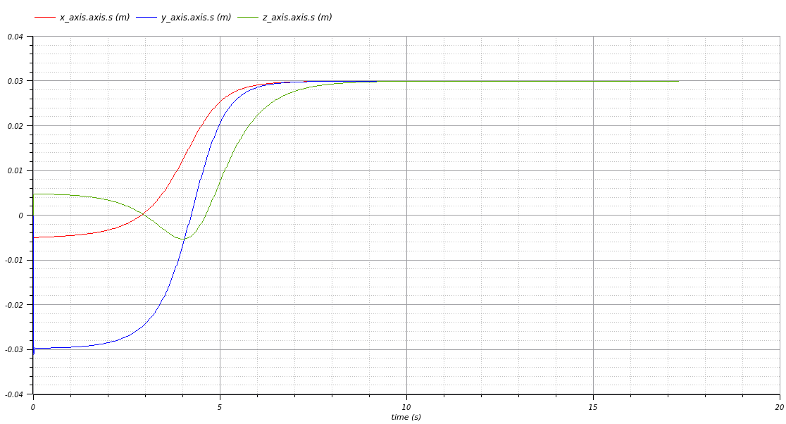
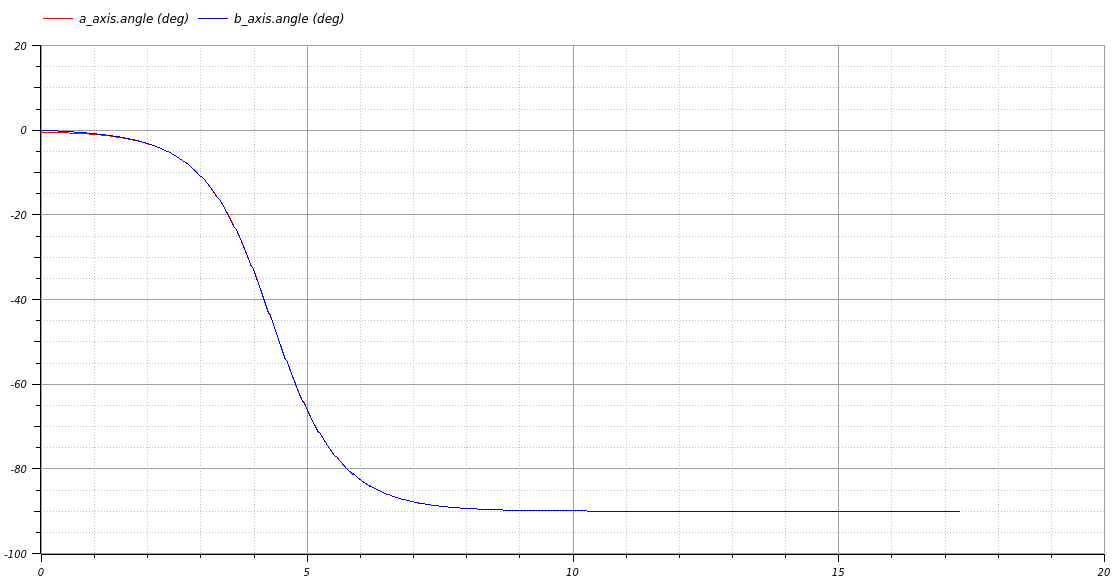
Here are the some plots of the modelica model running with the above tool targets:
![]()
![]()
![]()
The next part of the project will be to format the inverse kinematics solution into g-code so that I can run it on my milling machine and then to work on some routines for generating tool paths for milling.
-
Proof of Concept
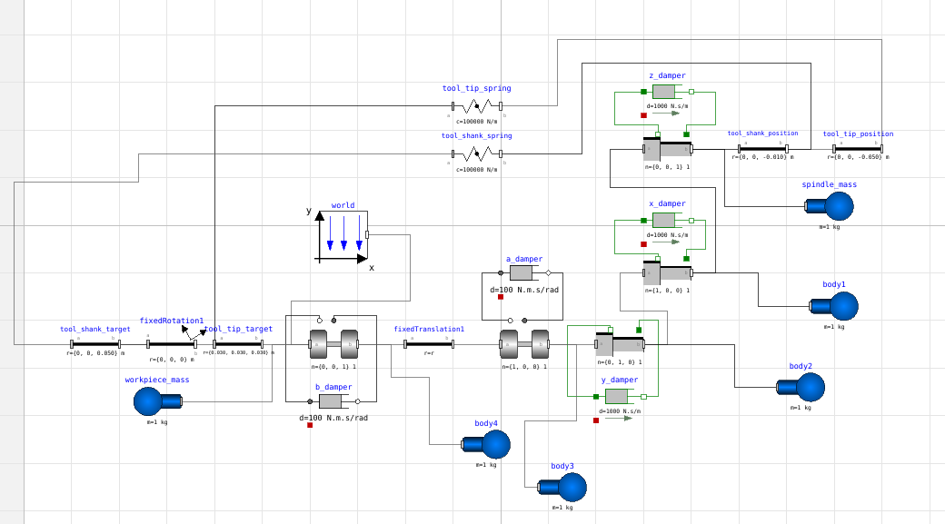
01/16/2020 at 01:26 • 0 commentsToday I put together a modelica model in using the multibody physics library from the standard modelica library to see if this idea about solving inverse kinematics with modelica will work.
![]()
The joints in the model match my pocketnc 5 axis milling machine. There's a damper on each joint and mass on each part of the machine. Springs connect the imaginary tool target position to the actual tool position. When the model is run, the tool moves toward the target position and eventually settles there.
![]()
![]()
Success! I've solved the inverse kinematics problem!... But only for one tool position.
The next step will be to make some custom modelica blocks to feed the model with a series of end effector target positions and to extract the joint positions.
Solving Inverse Kinematics with Modelica
Numerical simulation of halfway imaginary machines to generate instructions for real machines