Close
0%
0%

ReTest-yg

YG's own version of Mateng's ReTest, but with different features and a palindromic project number!

Similar projects worth following
As I'm playing with miniature relays from another age, I find that some of them have significant variance from the rest, which might create problems in the sensitive circuits I design.
I need to "bin" them and an automatic test rig is required.
Mats did something close but that is not adapted: I need current/voltage measurements to characterise the coil. And I don't use arduinos so I though "I'm just going to build a RPi adapter."

Well, 2 years later, I come back to this project and I simplify it, get rid of the RPi, use a mouse as input device (to read the relay output) and exploit the programmability of my latest digital PSU, so I can do everything on my main Linux laptop, over USB...

20181108 : project reboot !
The text below is a bit outdated but the purpose is still the same: test relays. However I only measure the hysteresis voltages now.

2020-02-04 : The hacked mouse and the SCPI lab PSU are among the many features of this video of the testing procedure :-)


Old version :

The РЭС15 are low-voltage small-signal relays built in Soviet Russia, brought to us by the magic of eBay. I use a certain quantity in #AMBAP: A Modest Bitslice Architecture Proposal and #SPDT16: 16-bits arithmetic unit with relays

In another page (Pre-Biased, or Hysteresis Relay Logic) I gather some measurements and find some outsiders that diverge about 20%. In practice, this can be enough to destabilize the circuit, particularly the latch bits that rely on magnetic hysteresis.

@matseng has designed his own relay timing analyser: #ReTest - Relay timing tester which I'm not able to replicate and doesn't provide me with data I need (such as coil voltages and currents).

I'm more comfortable with the Raspberry Pi (first generations) and this project is a good opportunity to play with some 74HC parts, precision current generators and other funky analog and digital circuits...


Logs:
1. Sampling
2. SPI Interface
3. Programmable current generator
4. Reboot !
5. Relevant datapoints
6. Got mouse.
7. And the PSU (bis)
8. First automated ramps
9. Relay labelling
10. Increase the resolution again...
11. Mouse button handling in C
12. Changes for the RES-64
13. No more FP23, use sed !
14. More mouse buttons handling in C
15. First plots
.

RES64.log

Log of the test results of 330 relays

x-log - 4.22 kB - 02/04/2020 at 23:57

Download

RES64.152ok.log

Von & Voff of 152 RES64 relays, used to plot stats etc.

x-log - 1.87 kB - 11/16/2019 at 23:56

Download

banc_test.2.sh

The test bench used to measure the hysteresis of the RES64

x-shellscript - 3.53 kB - 11/16/2019 at 19:53

Download

banc_test.sh

A first skeleton script for the test bench (uses some external sound files to help with remote operations)

x-shellscript - 871.00 bytes - 11/13/2019 at 01:38

Download

file_buttons.c

This program captures the /dev/input/mice events and updates the contents of 3 files in real time, for use with a bash script.

x-csrc - 3.22 kB - 11/12/2019 at 03:45

Download

View all 13 files

  • First plots

    Yann Guidon / YGDES11/16/2019 at 19:49 0 comments

    (updated again)

    Here it is !

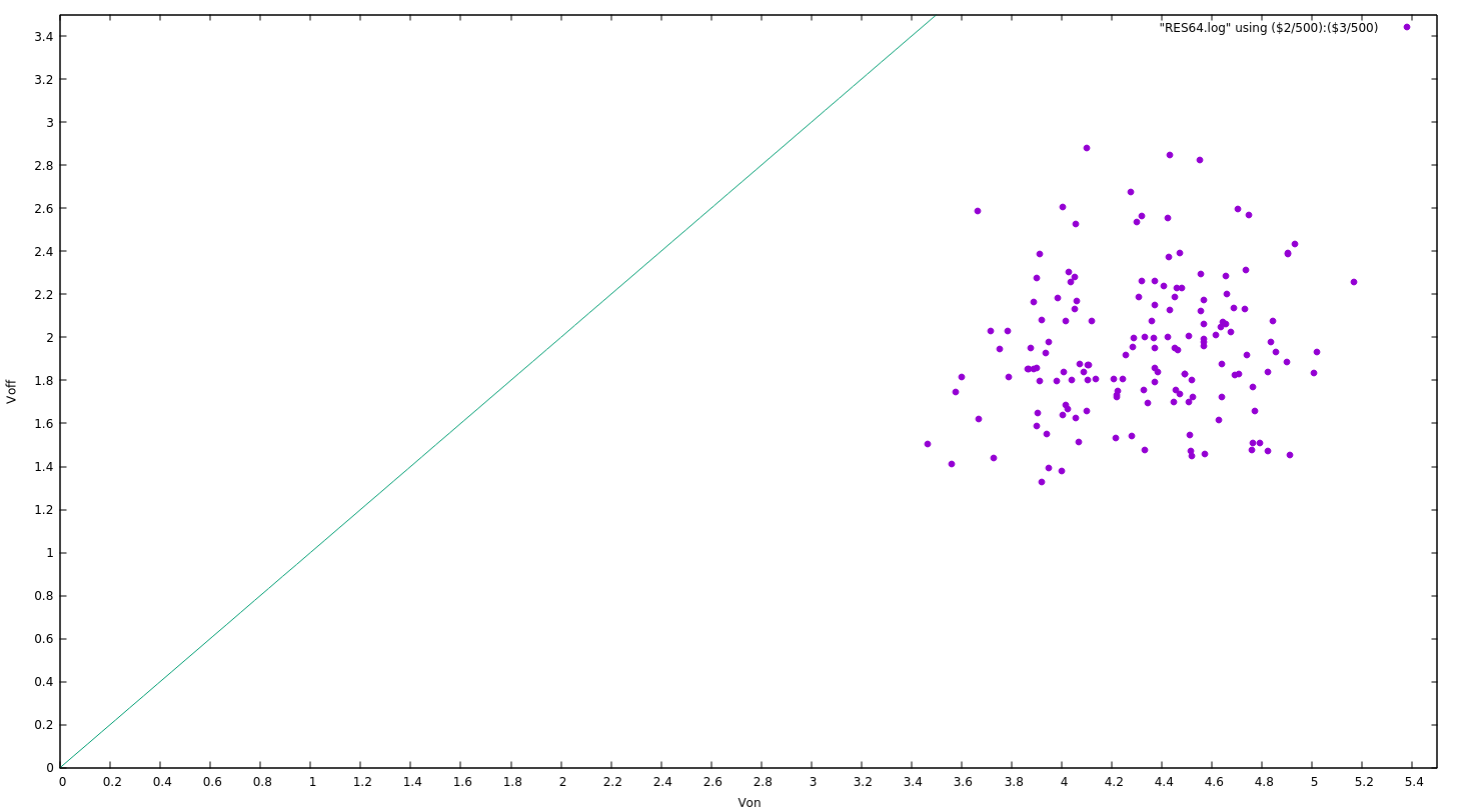
    The first plot of the Von/Voff of 90 RES64A relays, found on vseste's eBay store in Moldavia:

    The range is extended because the relay is in series with 4×2K Ohm resistors, the ratio is about ×5. Add another ×100 ratio because I count in steps of 10mV. What matters is that ALL the parts are tested in the exact same conditions and we have a pretty good scatter pattern. I still have 60 parts to test and 110 should arrive in the coming weeks.

    I have uploaded the script on the files section.


    153 relays have been tested and the results are looking good. 1 relay was DOA and will be sacrificed during an autopsy.

    I have uploaded the raw data as RES64.152ok.log and here are some early plots :

    X-Y plot

    gnuplot script:

    set xtics 0.2
    set ytics 0.2
    set xr [0:5.5]
    set yr [0:3.5]
    set xlabel 'Von'
    set ylabel 'Voff'
    d(x)=x
    plot "RES64.log" using ($2/500):($3/500) w points pt 7, d(x) notitle with lines linestyle 2

     I have traced the diagonal line because the distance from the point to the diagonal indicates the hysteresis.

    There are two applications for the relays and they are in 2 zones of the dot cloud :

    1. Amplifier/buffer : this requires a low Von so it's the leftmost dots
    2. Latch/flip-flop : they require a large hysteresis so they are furthest from the diagonal line.

    The "dots" will be allocated later when I have the whole stock but we can already see some of them used for specific purposes.

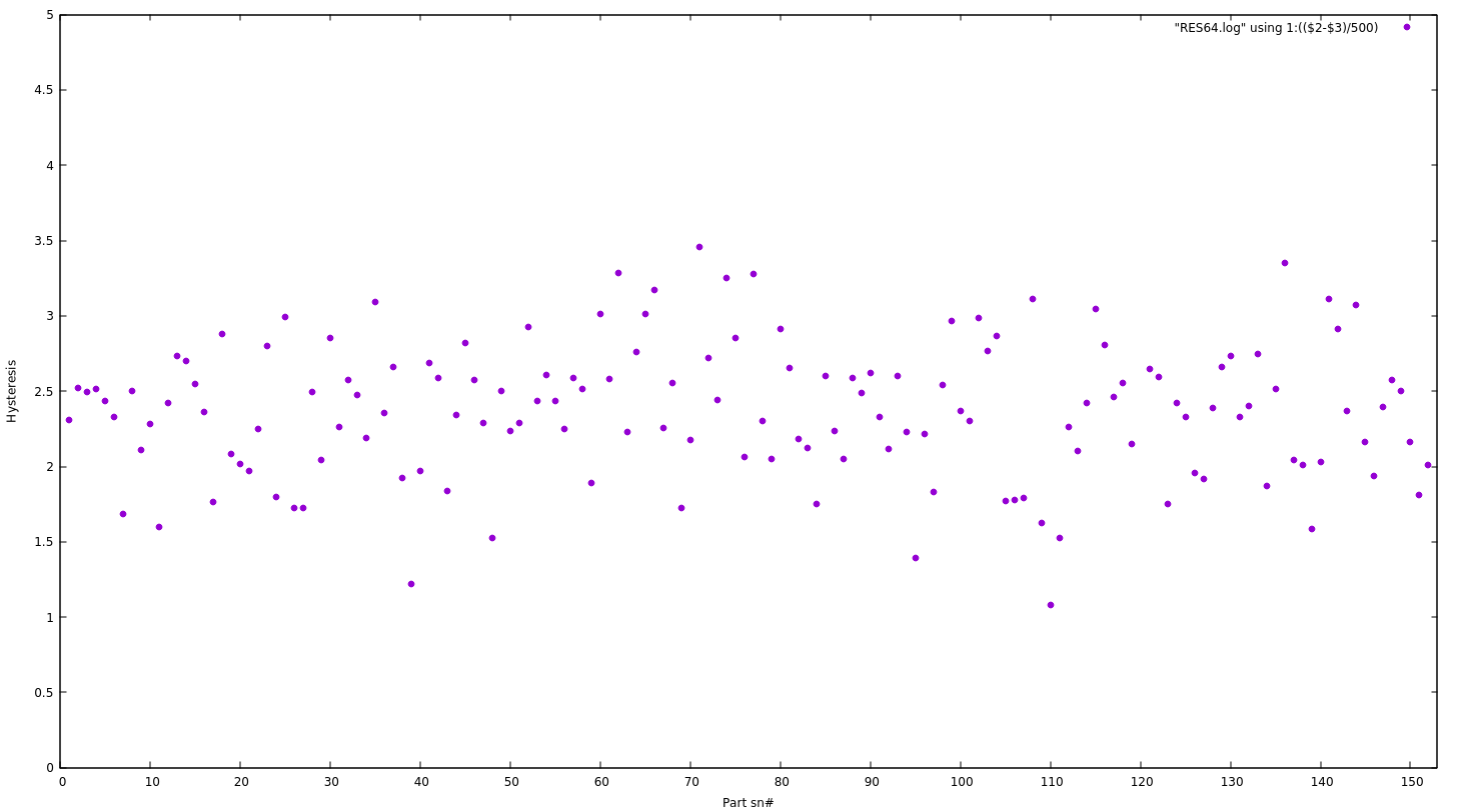
    Hysteresis

    gnuplot script:

    set ytics 0.5
    set xtics 10
    set ylabel 'Hysteresis'
    set xlabel 'Part sn#'
    set yr [0:5]
    set xr [0:153]
    plot "RES64.log" using 1:(($2-$3)/500) w points pt 7

    Apart from a few outliers, hysteresis is well between 1.5 and 3.5V.

    • The low hysteresis parts are suited as buffers, to lower the source's required swing
    • The high hysteresis parts are suited as latches, for better reliability

    Candidates for the buffers can be selected by first sorting the list by hysteresis, then sorting by Von.

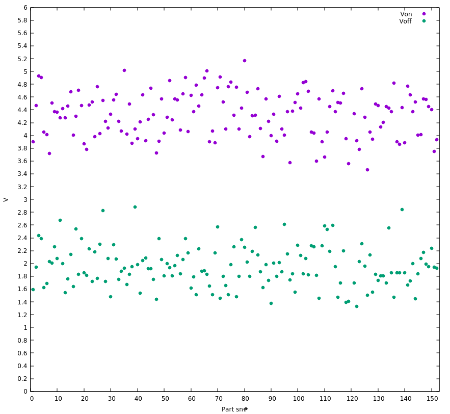
    Margin

    gnuplot:

    set xr [0:153]
    set yr [0:6]
    set ytics 0.2
    set xtics 10
    set xlabel 'Part sn#'
    set ylabel 'V'
    plot "RES64.log" using 1:($2/500) title "Von" w points pt 7, "RES64.log" using 1:($3/500) title "Voff" w points pt 7

    Even with the occasional outliers, we see the other major benefit of reed relays : there is a much larger "gap" between the Von and Voff clouds, compared to the RES15. The larger the gap, the less sensitive to parasites ! There is at least 1V of margin so the power supply can be less filtered => cheaper and more reliable !

    OTOH the "outliers" can be used as buffers.

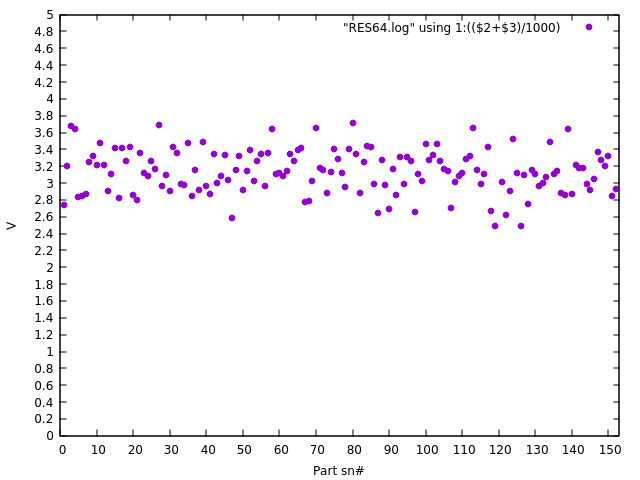
    Register set supply voltage

    gnuplot:

    set ytics 0.5
    set xtics 10
    set ylabel 'Hysteresis'
    set xlabel 'Part sn#'
    set yr [0:5]
    set xr [0:153]
    plot "RES64.log" using 1:(($2+$3)/1000) w points pt 7

    The question of the voltage to apply to the register set is critical as well, since reliability/retention are affected, but easy to evaluate : it's simply the average of Von and Voff, and is shown to be in a band centered around 3.2V. This means I can reuse the rails of the Numitron-based display modules, using -3.3V-0V-+3.3V. Or a 6.6V unipolar supply. Neat.

    The band's medium value and width will change once the "sensor" parts are taken out of the pool. Overall it's a great news because the comfortable margin (compared to the RES15-based R7) greatly simplifies the design of the power supply. Not only has the current dropped (thus reducing the size of the filtering capacitors as well as the self-heating-related drifts) but there can be only one regulator and tuning point (instead of one per board). And because the load is constant, the working point is set with a simple rheostat in series, of a lower rating than what was planned for the previous version that used RES15s.


    The register set will use a pair of relays for each bit and the first plot (XY) will help select the pairs : they are closest from each other. Maybe I can come up with some sort of automatic partitioning...

    "Matching"...

    Read more »

  • More mouse buttons handling in C

    Yann Guidon / YGDES11/12/2019 at 03:51 0 comments

    I created a new program : file_buttons.c

    It solves a problem I discovered : some events are not sent when the program starts so it would miss critical events in the previous system I considered.

    Now, the program is run in parallel with the script, which can read the values of the files button_left, button_middle and button_right.

    It's still missing a safety/check to prevent more than one instance from running.

  • No more FP23, use sed !

    Yann Guidon / YGDES11/03/2019 at 15:42 0 comments

    In the past, I have coded and uploaded FP23.c to convert the numbers and strings to a fixed point format that is recognised and written by the KA lab PSU series.

    I think I'll use bash anyway so any way to avoid C code is welcome :-) And I have decided to stick to a fixed 4-digits format, that is easily converted to the 5-digits&dot format used by the PSU. A couple of bash functions do the trick !

    function convertAmperes () {
      echo -n $1  | sed 's/^\([0-9]\)\([0-9]\)\([0-9]\)\([0-9]\)/\1.\2\3\4/'
    }
    
    function convertVolts () {
      echo -n $1  | sed 's/^\([0-9]\)\([0-9]\)\([0-9]\)\([0-9]\)/\1\2.\3\4/'
    }

    From there, it is easy to create simple loops and high resolution ramps :

    for V in $( seq -w 0 6000 ); do
      echo -n "VSET1:"$( convertVolts "$V" ) > $TTY
      sleep .1
    done

    I'll try to characterise a batch of RES64 and the quantity is smaller than the RES15 so I don't think I need a crazy AN3 labelling format.


  • Changes for the RES-64

    Yann Guidon / YGDES10/31/2019 at 02:53 0 comments

    Some changes are happening !

    The RES-15 has a pretty low hysteresis and high power draw. The RES-64 is bulkier and only SPST but who cares ? The hysteresis is more than 2V under 2mA only so it is better suited, more stable and resilient, less power-hungry...

    The testing strategy does not change but some electrical parameters do. Mainly it's the series resistor and the voltage range. The RES64 has a 2K ohm coil so a 10K series resistor increases the resolution by ×6 and the voltage shoots up to max 36V.

  • Mouse button handling in C

    Yann Guidon / YGDES11/18/2018 at 15:24 0 comments

    I just added a 3rd C file that reads the status of the mouse button. It follows the precedent log 6. Got mouse.

    It tries to be reasonably clever but be careful, it's a quick and dirty hack, like the other files :-D

    At least it reads the event source in a non-blocking way so the main program can poll the buttons at the desired state.

  • Increase the resolution again...

    Yann Guidon / YGDES11/18/2018 at 06:09 0 comments

    The 100 ohms resistors in series with the coil increase the voltage required to operate the relay.

    100 ohms + 40 ohm max for the coil makes the relay close at about 8V for certain units, instead of 2.3V max for the lone coil. This is good because the resolution of the measurement is increased, the digital PSU has 10mV steps so the virtual resolution is around 2.5V. I intend to almost double this resolution with another 100 ohms resistor in series, just to be safe :-P

    The max voltage might increase to 15 or 16V for certain outliers.

    The max. current will be set to 50mA because that's the maximum that the 1/4W resistor can handle:
    P=R×I² => I²=P/R => Imax = sqrt(P/R), and here we have P=1/4W and R=100.

    This also means that my C code must handle input and output of fixed point numbers in ASCII, while the internal resolution is an integer number of mV. I get a "fixed point 2.3" format (2 digits for Volts and 3 digits for millivolts) that fits in an unsigned short int (16 bits => 65.536V, while the PSU is limited to 61V) and this is useful for the current as well (in mA).

    I have added another C source code file that handles the conversion to/from ASCII format and integer millivolts. What else should I code now ?

  • Relay labelling

    Yann Guidon / YGDES11/18/2018 at 03:21 0 comments

    I'll have to automate many aspects of the binning process. However I still have to manually handle the parts.

    The computer will generate and store the characteristics with SSV log files, but the relays might be loose in bags or boxes. The relays must be marked, manually, because I have no fancy automated marker. There is only me and a fine marker. The marking must be short and practical...

    I decided to use an alphanumeric code : 2 or 3 digits, 0-F and A-Z. There are 36 codes per digit, which is the standard capacity of a box of RES15. This allows me to mark boxes with a prefix for easier lookup in the future.

    36×36=1296 relays : this is more than I think I can test myself so 2 digits are enough in the beginning but 3 is still possible (up to 46656 codes) because I own more than 1296 relays at this moment.

    The test software is written in C because of interfacing and timing constraints. Let's now write the conversion functions :

    • alpha to integer is required so the program knows where to start counting, from the command line or by scanning the previous log files.
    • integer to alpha because the computer must output the code on screen and on the log file.

    Beware, it's ugly but quickly coded.

    /*
    file AN3.c (c) 20181118 Yann Guidon whygee@f-cpu.org
    Alphanumeric3 code : 3 digits code up to 46656 values
    Not really foolproof but good enough for a hack or two.
    */
    
    #include <stdio.h>
    
    // the character string MUST be terminated
    // (by zero or space for example)
    int alphanum3_to_integer (char *a) {
      int val=0, i=0;
      char c;
    
      while (1) {
        if (i>3)
          return val;
    
        c=a[i++];
    
        if ((c >= '0') && (c <= '9')) {
          val = val*36;
          val += c-'0';
        }
        else {
          if ((c >= 'A') && (c <= 'Z')) {
            val = val*36;
            val += (c+10)-'A';
          }
          else
        return val;
        }
      }
    }
    
    // error can be checkd by looking if a[0] changed
    void integer_to_alphanum3(int val, char *a) {
      int div, rem;
    
      if (val >= 46656)
        return;
    
      div = val / 1296;
      if (div < 10)
        a[0]=div+'0';
      else
        a[0]=(div+'A')-10;
      val -= div * 1296;
    
      div = val / 36;
      if (div < 10)
        a[1]=div+'0';
      else
        a[1]=(div+'A')-10;
      val -= div * 36;
    
      if (val < 10)
        a[2]=val+'0';
      else
        a[2]=(val+'A')-10;
    }
    

    A small test shows it works:

    int main(int argc, char ** argv) {
      int i, j;
      char buff[6];
    
      for (i=0; i<46656; i++) {
        integer_to_alphanum3(i, buff);
        buff[3]=0;
        j = alphanum3_to_integer(buff);
        if (j != i)
          printf("%s : %d != %d\n", buff, i, j);
      }
      printf("\n");
    }
    

    ..

  • First automated ramps

    Yann Guidon / YGDES11/12/2018 at 05:08 0 comments

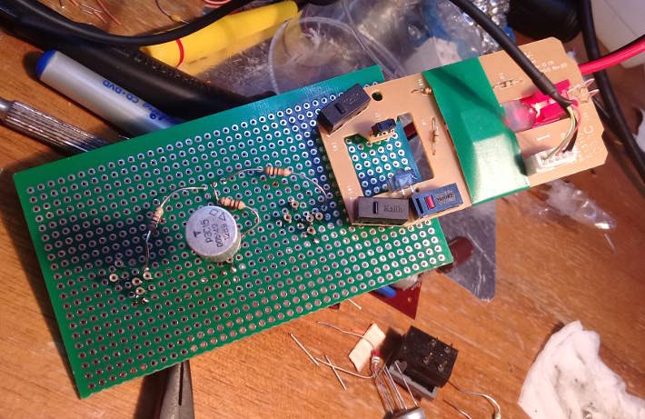
    I soldered the test board and tested the whole hardware :-)

    Not visible is the thick cable to the PSU to reduce losses (unlike the previous tests with a breadboard and ohmic losses here and there... Some measurements were off by maybe 10%)

    There were a few issues, for example the mouse would continually reset when connected to the hub at the same time as the PSU. So I found a new USB cable... and now it works. There is no flow control with the PSU so I have to insert wait statements everywhere...

    The following script is a crude example:

    # configure and check PSU
    TTY="/dev/ttyACM3"
    ls $TTY
    stty 9600 cs8 raw -echo -echoe -echonl -echoprt -echoctl -echoke -parenb -F $TTY
    sleep .1
    echo -n "*IDN?" > $TTY
    sleep .1
    
    #test the mouse souris
    MOUSE="/dev/input/mouse1"
    ls $MOUSE
    
    #start in another terminal : od -An -v -w1 -t x1 $MOUSE
    
    #turn off:
    echo -n "OUT0" > $TTY
    sleep .1
    #set max current
    echo -n "ISET1:0.060" > $TTY
    sleep .1
    #set output voltage
    echo -n "VSET1:0" > $TTY
    sleep .1
    #turn on:
    echo -n "OUT1" > $TTY
    sleep 2
    
    for i in 0 1 2 3 4 5 6 7 8; do
       echo -n "VSET1:"$i >> $TTY;
       echo $i"V";
       sleep .6;
    done
    
    for i in 7 6 5 4 3 2 1 0; do
       echo -n "VSET1:"$i >> $TTY;
       echo $i"V";
       sleep .5;
    done


    I won't go much further with Bash, because it's not practical enough. I'd use Python if I was better but I'll stick to C. 

    Here is how it works so far :

    At the end of the script, one terminal window shows that the mouse has sent 2 packets that indicate the relay closing and then opening : success !


    Things to know : I have increased the series resistor to 100 ohms because it increases the resolution. The PSU can only set the output voltage with 10mV steps and a higher resistance increases the voltage required to latch the relay, so I get an equivalent resolution of 2.5mV (approx.). All the relays will be tested under the same conditions so the actual voltage doesn't matter, as long as the measurements cluster the values of similar coils.

    The mouse has 3 buttons so I wired 3 sockets for the relays and I could test 3 sockets in parallel (with the appropriate SW)?

    I have already observed pretty significant variations in the latching voltages of 3 relays... But better SW is required now.

  • And the PSU (bis)

    Yann Guidon / YGDES11/11/2018 at 19:55 0 comments

    A year ago I started to use my new digital PSU and the early logs are there : https://hackaday.io/project/20733-hot-logic/log/56927-and-the-psu. Today I have set it up again and these logs and the files are very helpful :-)

    But first I had to connect my computer to the lab PSU, which are more than 2m apart. Fortunately I found in my stock a hub and enough AtoB USB cables to connect the PSU and the mouse close to the bench. It should be moderately practical :-)

    Plugging the PSU through the hub :

    [1069116.978946] usb 2-1.3: new full-speed USB device number 28 using ehci-pci
    [1069117.058694] usb 2-1.3: New USB device found, idVendor=03eb, idProduct=3301
    [1069117.058708] usb 2-1.3: New USB device strings: Mfr=0, Product=2, SerialNumber=0
    [1069117.058714] usb 2-1.3: Product: Standard USB Hub
    [1069117.061972] hub 2-1.3:1.0: USB hub found
    [1069117.062213] hub 2-1.3:1.0: 4 ports detected
    [1069117.348953] usb 2-1.3.2: new full-speed USB device number 29 using ehci-pci
    [1069117.461864] usb 2-1.3.2: New USB device found, idVendor=0416, idProduct=5011
    [1069117.461878] usb 2-1.3.2: New USB device strings: Mfr=1, Product=2, SerialNumber=3
    [1069117.461884] usb 2-1.3.2: Product: USB Virtual COM
    [1069117.461889] usb 2-1.3.2: Manufacturer: USB Vir
    [1069117.461894] usb 2-1.3.2: SerialNumber: NT2009101400
    [1069117.465957] cdc_acm 2-1.3.2:1.0: ttyACM3: USB ACM device
    

    yup, the same /dev/ttyACM3 as before :-)

    From now on, everything must be done by root, or the user should be added to the relevant group.

    export TTY=/dev/ttyACM3

    Then configure the serial port : file serial9600.sh

    #!/bin/bash
    #1 start, 8 data, 1 stop, no parity
    
    TTY=/dev/ttyACM3
    stty 9600 cs8 raw -echo -echoe -echonl -echoprt -echoctl -echoke -parenb -F $TTY

     And now we can talk !

    on one terminal, display the port's output with

    # od -An -v -w1 -t c /dev/ttyACM3 

     In another terminal, send a SCPI command :

    echo -n "*IDN?" > $TTY

    I get the following result :

    [root@localhost yg]# od -An -v -w1 -t c /dev/ttyACM3 
       K
       O
       R
       A
       D
       K
       A
       6
       0
       0
       2
       P
       V
       2
       .
       0
      \0
    

    It's working !


    The relevant vocabulary is quite simple :

    • Identify :
      echo -n "*IDN?" > $TTY
    • Turn output off :
      echo -n "OUT0" > $TTY 
    • Turn output on :
      echo -n "OUT1" > $TTY 
    • Set max. current to 0.42A :
      echo -n "ISET1:0.42" > $TTY
    • Read back the max. current setting :
      echo -n "ISET1?" > $TTY 
    • Read the actual output current :
      echo -n "IOUT1?" > $TTY 
    • Set the output voltage to 12.34V :
      echo -n "VSET1:12.34" > $TTY
    • Read back the voltage setting :
      echo -n "VSET1?" > $TTY 
    • Read the measured output voltage :
      echo -n "VOUT1?" > $TTY 
    • Read the status :
      echo -n "STATUS?" > $TTY

      (the result is binary and the bits must be interpreted)

    • Some more commands exist (see the references in the previous log) but I'll only play with the voltage.

    .

    .

  • Got mouse.

    Yann Guidon / YGDES11/11/2018 at 07:07 0 comments

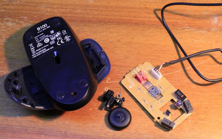
    The new ReTest uses a mouse.

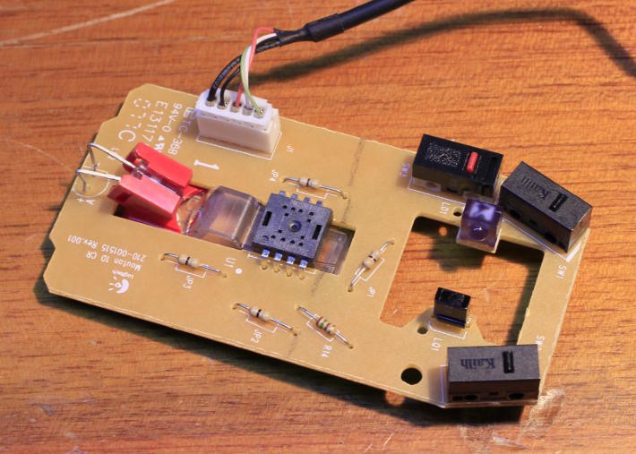
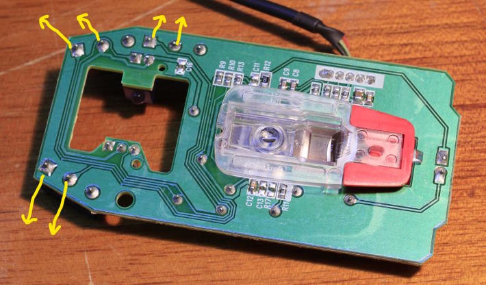
    A nicely hacked mouse because I only need one input bit. Apparently this one can provide 3 so I could test 3 relays at the same time :-P


    I found a used USB mouse with its wires and it perfectly fits my needs.

    I only have to replace the buttons with the relay contacts :-) I leave the casing/wiring work for later...


    Software is a different matter though, but not as difficult as it could have been. That's why using a mouse (a very common and mundane peripheral) is a great solution : cheap, widely used and very well documented.

    First I had to disable it in Xorg : it's a matter of 1) finding the right peripheral 2) writing the right file at the right place. 1) is solved easily with dmesg, xinput, cat /proc/bus/input/devices ...

    $ xinput list
    ⎡ Virtual core pointer              id=2   [master pointer  (3)]
    ⎜   ↳ PS/2 Generic Mouse            id=12  [slave  pointer  (2)]
    ⎜   ↳ SynPS/2 Synaptics TouchPad    id=13  [slave  pointer  (2)]
    ⎜   ↳ Logitech USB Optical Mouse    id=17  [slave  pointer  (2)]
    ...
    
    $ dmesg
    [1015128.994372] usb 2-1.3: new low-speed USB device number 86 using ehci-pci
    [1015129.078062] usb 2-1.3: New USB device found, idVendor=046d, idProduct=c077
    [1015129.078069] usb 2-1.3: New USB device strings: Mfr=1, Product=2, SerialNumber=0
    [1015129.078073] usb 2-1.3: Product: USB Optical Mouse
    [1015129.078077] usb 2-1.3: Manufacturer: Logitech
    [1015129.083902] input: Logitech USB Optical Mouse as /devices/pci0000:00/0000:00:1d.0/usb2/2-1/2-1.3/2-1.3:1.0/0003:046D:C077.0007/input/input62
    [1015129.084707] hid-generic 0003:046D:C077.0007: input,hidraw1: USB HID v1.11 Mouse [Logitech USB Optical Mouse] on usb-0000:00:1d.0-1.3/input0
    
    $ cat /proc/bus/input/devices | grep "Name\|Handlers"
    ...
    N: Name="Logitech USB Optical Mouse"
    ...
    $ less /proc/bus/input/devices
    ...
    I: Bus=0003 Vendor=046d Product=c077 Version=0111
    N: Name="Logitech USB Optical Mouse"
    P: Phys=usb-0000:00:1d.0-1.3/input0
    S: Sysfs=/devices/pci0000:00/0000:00:1d.0/usb2/2-1/2-1.3/2-1.3:1.0/0003:046D:C077.0006/input/input61
    U: Uniq=
    H: Handlers=mouse3 event17
    ...

    The last command shows that the device is handled by /dev/input/mouse3 and /dev/input/event17. This is easily verified.

    2) the right file is a new file in /etc/X11/xorg.conf.d/01-no_optical_mouse.conf

    Section "InputClass"
       Identifier     "Desactive souris Logitech"
       MatchIsPointer "on"
       Driver         "evdev"
       MatchProduct   "USB Optical Mouse"
       MatchVendor    "Logitech"
       Option         "Ignore" "true"
    EndSection
    

     After I restarted the X server, the mouse is now mute and deaf, but I still can read data from it !

    sudo od -An -v -w1 -t x1 /dev/input/mouse3
     09
     00
     00
     08
     00
     00
    

     that's the binary dump when I press and release the left button.

    The binary protocol is really straight-forward so now I focus on the PSU...


    Update : 20181118 see log 10.Mouse button handling in C

View all 15 project logs

Enjoy this project?

Share

Discussions

Yann Guidon / YGDES wrote 11/18/2018 at 07:47 point

Oh ! a cute little page about the РЭС15  :-D
http://www.155la3.ru/res15.htm

  Are you sure? yes | no

Yann Guidon / YGDES wrote 11/01/2016 at 13:37 point

Hopefully, this system will be a good basis to build the Ge PNP tester because I have even more transistors to test/bin for #Germanium ECL :-D

  Are you sure? yes | no

matseng wrote 11/01/2016 at 12:36 point

How would it work with using two mcu/cpu timers/counters, one of them driven with an inverted signal (unless the counter can increment on both rising and falling edges).  Then one could simply check the counter values to determine if any bouncing has occurred since the last poll of the counters.

One pair of counters would be required each for the NC respective NO contacts.

Of course there would be issues with the minimum high/low time of the counter clock, so really short pulses could be missed anyways, but a reasonably nice ARM mcu should(?) have counters that can operate in the range of 10's of MHz I guess.

  Are you sure? yes | no

Yann Guidon / YGDES wrote 11/01/2016 at 12:41 point

what if the counter(s) wrap around ? They have to saturate, and we don't actually care about the count, so it goes back to a set/reset latch :-)

  Are you sure? yes | no

matseng wrote 11/01/2016 at 12:57 point

Well, if it was an 8 bit counter you'd be able to detect it anyways, as long as you don't get exactly 256 pulses between the samples). And with 16/32 bit counters there's basically no way that there will be that many pulses between samples.

Anyways you'd probably acquire data for a number of actuations  so even the 1/256 chance of losing a period of bounces between two 10us (or whatever period) samples wouldn't be a big deal.


I'd consider the ability of programmatically adjust the coil voltage and also measure the coil current and the back emf voltages to be more pressing issues if I'd make a new revision.


And for the measurement of coil voltages and currents there probably is a need for peak-hold circuity before the A/D's unless sampling at a really high speed....

  Are you sure? yes | no

Yann Guidon / YGDES wrote 11/01/2016 at 13:09 point

I'm not looking at microcontrollers so I'm not trying to work around their idiosynchrasies :-) Of course a 32 bits counter will be hard to overflow but you'd need 4 of them and this gets us into high-end MPU world (whereas a 74HC74 costs close to nothing, when you have one).

Yes, a hundred cycles will get a good picture of the bouncing behaviour but it also depends on your resolution and we're back in the sampling theory :-)

My approach to drive the coil is with a programmable current generator, I'm trying to figure that out now. I've already done a 4-bits current generator for another test rig but I'd need 256 steps of 0.25mA to get a reasonable resolution. The relays shouldn't need more than 64mA to turn on, otherwise they're "not good".

Because I'll control the coil current, I will only need to measure a stable voltage at the coil's pins. Back EMF peaks depend on the current change speed so it's not worth measuring (too application-specific).

I have a few more logs to write now :-D

  Are you sure? yes | no

matseng wrote 11/01/2016 at 13:19 point

Aha...  That's a kinda interesting approach to drive them with constant current - as long as the compliance voltage is high enough to get a reasonable constant current.

But would you drive the relays with constant current in a real operating situation?

  Are you sure? yes | no

Yann Guidon / YGDES wrote 11/01/2016 at 13:33 point

Not exactly constant current but have a look at these logs:

https://hackaday.io/project/14628-ambap-a-modest-bitslice-architecture-proposal/log/45484-my-first-pre-biased-relay-logic-gates

https://hackaday.io/project/14628-ambap-a-modest-bitslice-architecture-proposal/log/45438-pre-biased-or-hysteresis-relay-logic

The coil current becomes an important factor, and it drifts under use so 20% of initial variation in the relay can upset some bits when the machine heats up. I store bits with hysteresis (cheap! fast! easy!) and I don't want them to be altered :-)

Additionally, I try to optimise the power consumption which is affected a lot by the high-fanout control signals. If I set the driving current to 65mA for a string (absolute worst case to turn all relays on), I consume more energy than if I set it to 55mA (worst case for most relays). That's why I need to bin with current.

Back EMF is not a concern with my topologies: my scope shots show no overshoot. A small cap helps, but the bias resistor provides a reasonable dissipative current path (no diode) and the current swing is lower than usual systems, so less energy to evacuate.

My pre-biased relay system is more or less a curren-driven one, in fact, so yes it's important to measure it :-)

  Are you sure? yes | no

Similar Projects

Does this project spark your interest?

Become a member to follow this project and never miss any updates