Brian Barrett
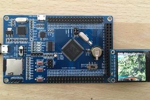
The idea behind the pyEC is that there are a number of layers interconnected to provide just the functionality you need and none of what you don't. The main board, or "Layer" as I've taken to calling them, is the main pyBoard v1.1 compatible board. It has a ton packed into a 4cm*4cm package. 50 pin header for inter-layer communications, CAN, OP Amp, Buzzer, LEDs, SD Card socket, user & reset switches and of course USB for debugging and loading on new programs. Most connectivity has been moved to other "layers". The "Control Layer" is just that, it controls all the layers and has the MCU. Without any additional layers it can basically just blink and beep.
Layers
Control Layer - pyBoard v1.1 compatible board w/USB, SD Card, Buzzer, USR/RST Switches and an RGB LED
Serial Layer - Exposes 4 Serial ports complete with RX/TX LEDs for easy debugging and 3.3V/5V level shifters
Input Layer - Gives 5 switch Inputs and 2 Analog inputs, all with optional voltage dividers to scale inputs
Power Layer - Power input (12V), 5V output, 2 High power & 3 Low power digitally controlled outputs
Kelly Layer - 24V Step-Up converter, DAC Outputs, digital Outputs & UART. Designed for Kelly KLS-S controllers
Battery Backup Layer - Provides LiPo charging and either 5V stable output from LiPo
IMU Layer - Provides a WIT Motion IMU through either I2C or serial. GPS input and direct IMU access ports are provided.
Test Layer - Exposes all pins from the Control Layer as well as buttons / LEDs on IO pins and Potentiometers for ADCs
 danjovic
 radiona.org
 Just4Fun