Grant Stankaitis
-
Haptic Sleeve Testing Program
06/30/2020 at 19:16 • 0 commentsQuick update here! I have uploaded the final Haptic Sleeve Testing Program and documentation to Github. The testing program allows us to programmatically send commands to the Haptic Sleeve and log input from the user.
The full documentation for the code is located in the readme here! The readme contains all the steps to setup your environment before running the testing program.
To find the Bluetooth mac address of your ESP32, see this link for Windows. Additionally, you can run the code below on your ESP to get the MAC address through uPyCraft:
import network #network library to wirelessly access things
import ubinascii #to decode the mac address
station = network.WLAN(network.STA_IF)#declare station interface
station.active(True) #activate the interface
station.connect("D2D4B4", "L2C26C2C10656")#only connects to 2.4GHz

if(station.isconnected()):
    print("Station connected!")
    print('network config:', station.ifconfig()) # Print IP address
    # ifconfig is linux eqvt to ipconfig for windows
    print('MAC address:', station.config('mac')) #original form
    mac = ubinascii.hexlify(station.config('mac'),':').decode()
    print('MAC address (decoded):', mac)

# The last two lines are used to print out the mac address
Double check: Your computer's Bluetooth is enabled and is able to discover the ESP32 named "Haptic Sleeve" (or a different name if you changed the device name).
-
Final ESP32 code
06/26/2020 at 20:20 • 0 commentsFirmware and Github update
I have updated the Github repository with the finalized code for the ESP32.
I was having major issues with the BLE Generic Attribute Profile being duplicated. This was a problem because it was causing issues when I was trying to connect programmatically using Python from my PC. For some reason, the service was being duplicated when BLE was initializing, and I tried to track down where the issue came from. Ultimately, I came to the conclusion that it was a firmware issue, and I tried flashing different versions of the Micropython firmware with no luck. Then, "esp32-idf4-20200617-unstable-v1.12-550-g4b5dd012e.bin" firmware was released, so I flashed the ESP32 with this firmware and it fixed the issue! I have uploaded this firmware file to the Github repository so that others can flash the same firmware.
Final code
Once the duplicate service issue was solved, I decided to consolidate my code into one file. The file "main.py," under the "ESP32 Code" folder on Github, is the main code running on the ESP32. This code contains the setup for the Nordic UART Service and handles activating the motors when commands are received. The file "boot.py" runs at every boot-up, importing the necessary Micropython modules and configuring/activating BLE.
"boot.py" and "main.py" can be uploaded to the ESP32, and now you have the fully-functional Haptic Sleeve running!
NOTES
In the final "main.py" code, the pin numbers for the motors are different from those used when testing. The pins were changed because they were closer to route on the PCB. Additionally, the pins for the motors were accidentally routed to pins on the ESP that cannot output PWM, so I cut the traces and soldered jumper wires to the nearest PWM-ready pins. Make sure these pin numbers are correct, and if needed you can change them for future revisions.
-
Final BLE & PWM testing in uPyCraft IDE
05/07/2020 at 21:29 • 0 commentsIn this log, I switched back to uPyCraft IDE and (spoiler) everything functions perfectly! I'll be wrapping up the code in this log. My finalized code can be found in my GitHub repository.
Switching back to uPyCraft IDE
Returning to uPyCraft IDE, I revisited the MicroPython examples posted in an earlier log (link found here). When I went through these examples, I discovered that they implemented the Nordic UART Service! I wanted to implement this BLE service from the beginning, and was unable to with Zerynth, so I am very happy that I can properly implement it within MiroPython using uPyCraft IDE.
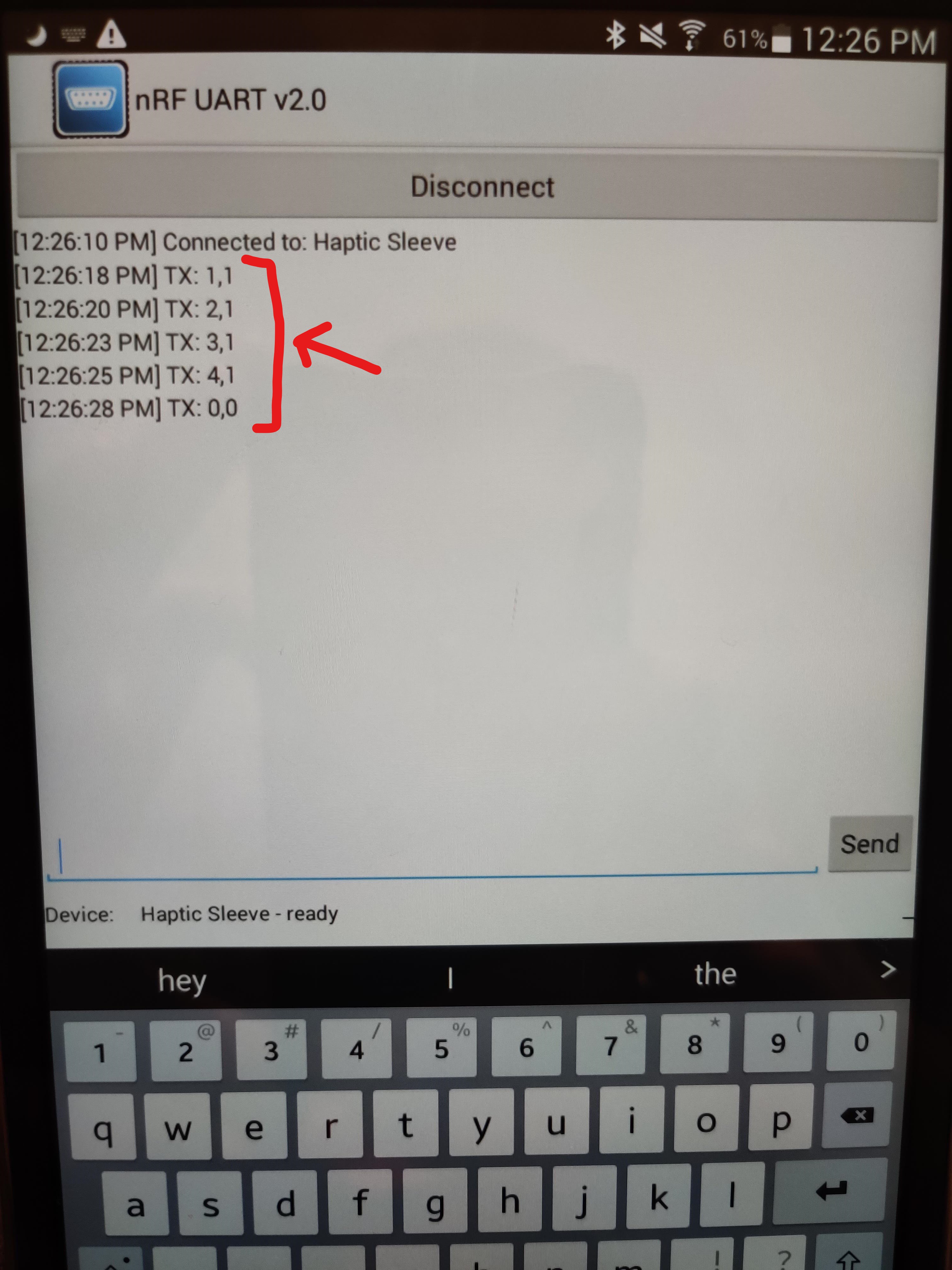
As you can see in the pictures below, there is proper connectivity between the nRF UART app and the ESP32 with my initial tests. The values being sent via the nRF UART app are being printed instantly to the ESP32 console. This is fantastic because it means we can have a constant stream of data going to the ESP32 (and/or send data back, like battery status).
![]()
![]()
The nRF UART app can be found here: nRF UART app (Android). There is a version for iOS devices, but I was unable to find the link at this time.
Finalizing code
Now that everything is fully functional (BLE, PWM motor activation, etc.), I spent time cleaning up my code. I split the code into two separate files. One file is bleuart.py. This file contains all of the BLE advertising, event handling, UART setup, etc. The contents of this file are pulled from the MicroPython example link found above. There were a few things that I changed, like setting the Bluetooth name of the ESP32 to "Haptic Sleeve" in the init method for the BLE UART class:
...
def __init__(self, ble, name="Haptic Sleeve", rxbuf=100):
...
Then, the rest of the code is contained in the main_BLE.py file. This is the main file that is executed when the ESP32 boots, and contains the BLE implementation, PWM motor activation, etc. The main_BLE.py file imports the bleuart.py file (seen in the import statements at the top of the file) so that BLE can be implemented. I keep the BLEUART class separate to maintain a more object-oriented approach.
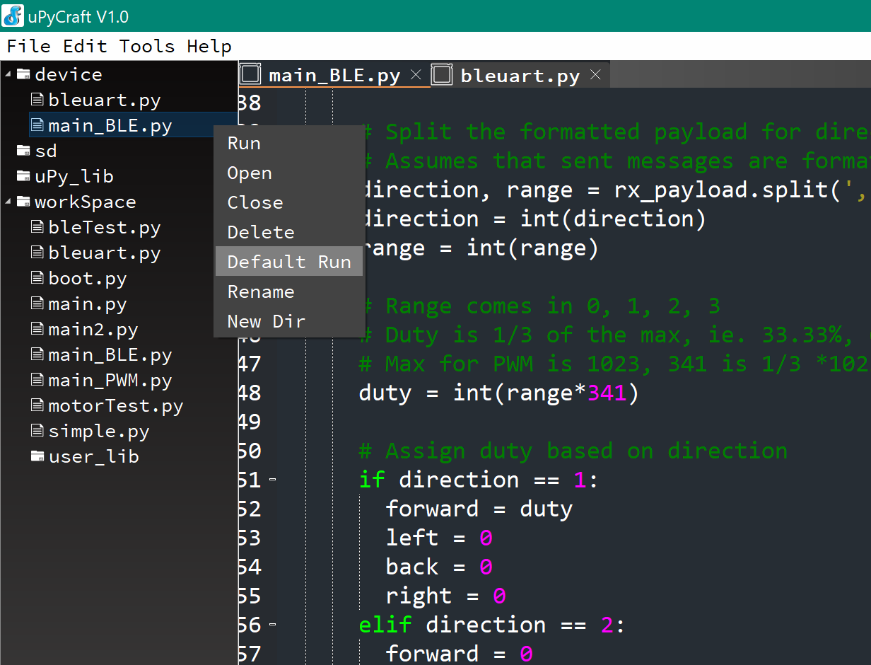
To ensure that main_BLE.py runs by default, right-click main_BLE.py and select "Default run."
![]()
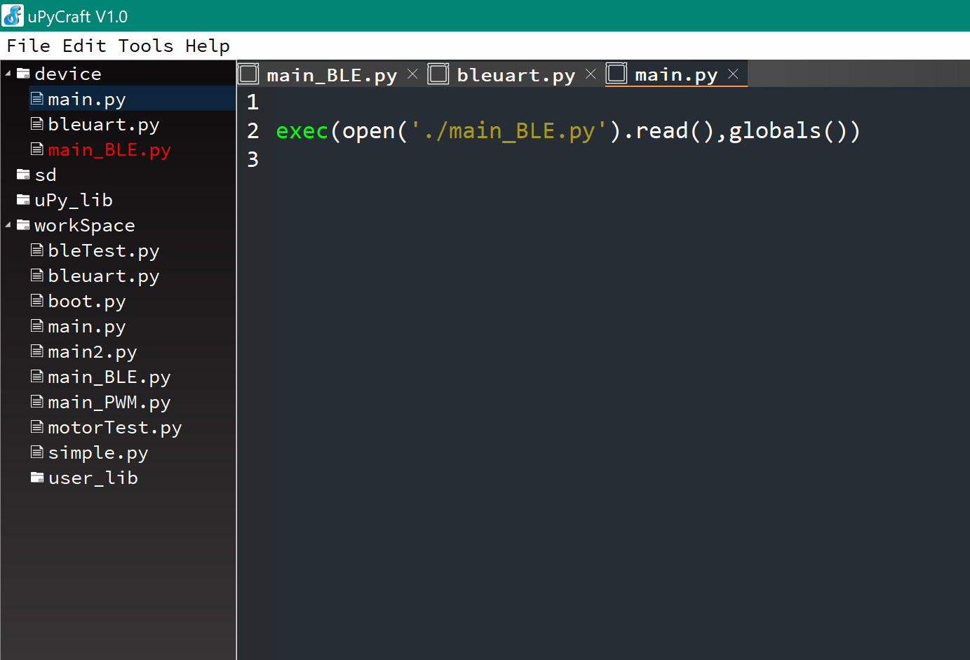
After selecting this, another file will be created called main.py, and main_BLE.py will be highlighted in red. This means that setting the "default run" worked. If you open main.py, you can see a command to open and execute the main_BLE.py file. So, main.py is the main file that runs, but since there is a call to execute main_BLE.py within this, it effectively runs main_BLE.py every time the ESP32 is set to execute the main code (like from power up).
![]()
PCB assembly
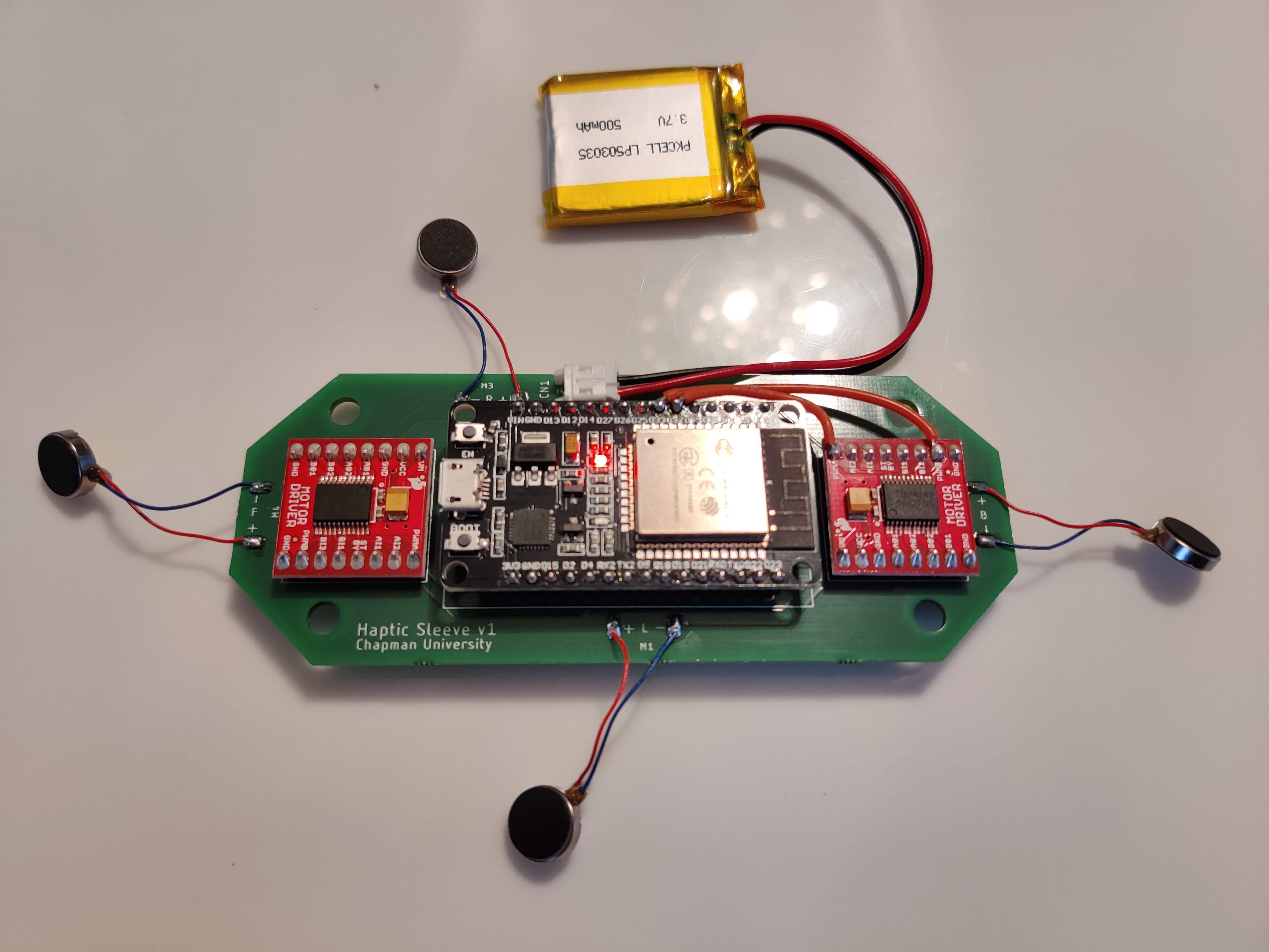
Now that the code is buttoned up and uploaded to the ESP32, I moved everything over to the PCB! I soldered the ESP32 and motor drivers in the proper orientation according to the layout, and added the JST connector for battery connections. The only issue was that I incorrectly wired the PWM pins for the second motor driver. Zerynth's implementation allows PWM on all digital pins, but MicroPython does not allow PWM generation from GPIO pins 34-39, and I routed my pins to GPIOs 34 & 35. So I had to cut the traces and externally route the wires to acceptable pins (hence the extra red wires running from the motor driver on the ride side of the picture). The jumper wires are now running to pins 32 and 33. After these slight modifications, I plugged the battery in and the ESP32 powered up! I verified that I was able to connect via Bluetooth to the ESP32 and send a full range of commands to activate the motors. So, the only part left to do is test it on humans!
![]()
-
Testing PWM with Zerynth & issues
05/07/2020 at 20:26 • 0 commentsIn the last log I said that I was going to work on transferring the coder over to Zerynth, so here's the documentation of that process! (And the issues I ran into along the way).
Porting main_PWM.py to Zerynth
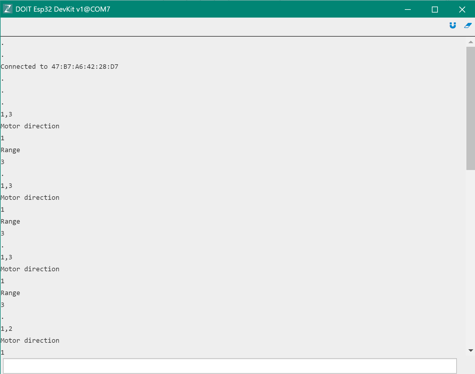
See the screenshot below of the ESP32 parsing the inputs sent over BLE in the same manner as the main_PWM.py code.
![]()
Now that I have the motor direction and range stored in the right variables, the next step is using these values to perform PWM activation of the motors!
Zerynth PWM
There are some similarities when moving the code over to Zerynth because Zerynth is designed to use a mix of Python and C code. However, Zerynth implements its own PWM module, so I had to convert the code to be compatible with their implementation of PWM. See the code below of the Zerynth implementation of PWM.
# Set up pins as PWM
forward_pin = D18.PWM
left_pin = D19.PWM
back_pin = D22.PWM
right_pin = D23.PWM

# Set pins as output
pinMode(forward_pin, OUTPUT)
pinMode(left_pin, OUTPUT)
pinMode(back_pin, OUTPUT)
pinMode(right_pin, OUTPUT)

# Set all to 0 (disabled until activated)
pwm.write(forward_pin, 0, 0)
pwm.write(left_pin, 0, 0)
pwm.write(back_pin, 0, 0)
pwm.write(right_pin, 0, 0)
The code below is the Zerynth implementation of the PWM activation via the equivalent sub_cb() function from main_PWM.py:
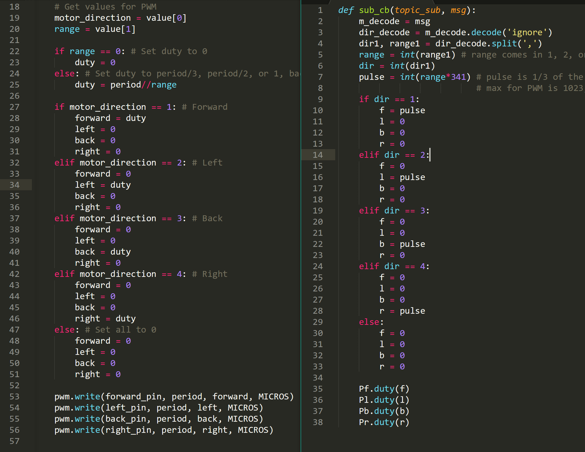
forward = 0
left = 0
back = 0
right = 0

# MICROS so every sec is 1000000 of micros, 1000 = 1kHz
frequency = 1000
period = 1000000//frequency

def set_PWM(status,value):
    # Check incoming commands and write PWM
    global duty
    global forward
    global left
    global back
    global right

    # Get values for PWM
    motor_direction = value[0]
    range = value[1]

    if range == 0: # Set duty to 0
        duty = 0
    else: # Set duty to period/3, period/2, or 1, backwards from original
        duty = period//range

    if motor_direction == 1: # Forward
        forward = duty
        left = 0
        back = 0
        right = 0
    elif motor_direction == 2: # Left
        forward = 0
        left = duty
        back = 0
        right = 0
    elif motor_direction == 3: # Back
        forward = 0
        left = 0
        back = duty
        right = 0
    elif motor_direction == 4: # Right
        forward = 0
        left = 0
        back = 0
        right = duty
    else: # Set all to 0
        forward = 0
        left = 0
        back = 0
        right = 0

    pwm.write(forward_pin, period, forward, MICROS)
    pwm.write(left_pin, period, left, MICROS)
    pwm.write(back_pin, period, back, MICROS)
    pwm.write(right_pin, period, right, MICROS)
To see the similarities/differences more clearly, here is a side-by-side comparison of the bodies of the functions. On the left is the Zerynth implementation and on the right is the main_PWM.py implementation:
![]()
Issues with Zerynth PWM
I was having some very strange issues with PWM activation when using Zerynth. I was running the same code as above, however it was activating more than one motor at once. When testing main_PWM.py, it was only activating multiple motors at once.
To get a better understanding of the issue, here is what was happening. For example, when I activate Motor 1, I can confirm via print statements that only the duty for one motor is being set at a time, and all others are 0. When I first set only the duty for Motor 1, this is the case. However, if I then set the duty for Motor 2, Motor 1 continues working and Motor 2 is activated, even though the duty for Motor 1 should be set to 0 (and I can confirm that it is being set to 0). When I set all motors to 0, they turn off in unison as expected. However, when I try to activate Motor 2 again, Motor 2 and Motor 1 turn on together again. It seems they are somehow tied together even though I can confirm that this portion of the code works in the original main_PWM.py file.
I concluded that the issue is derived from this portion of the code:
if motor_direction == 1: # Forward
        forward = duty
        left = 0
        back = 0
        right = 0
    elif motor_direction == 2: # Left
# ... other options removed for brevity

    pwm.write(forward_pin, period, forward, MICROS)
    pwm.write(left_pin, period, left, MICROS)
    pwm.write(back_pin, period, back, MICROS)
    pwm.write(right_pin, period, right, MICROS)
When the PWM module is writing to the motors, they somehow get tied together in what I suspect to be some form of an overflow. I think this is due to the way that Zerynth abstracts the programming out a layer, so you are not directly interfacing with the board like in uPyCraft IDE. Something must get tied up or stored within this layer of abstraction that causes previously activated motors to turn on. I'm not sure what this "something" is, so this is just a hypothesis.
Determined to figure out this issue, I spent countless hours debugging the code to no avail. I posted on the Zerynth Community support page and a Zerynth team member was unable to help me as well. The Zerynth team member noted that they will be testing this bug and pushing bux fixes in future updates. So, I explored other options!
I returned back to uPyCraft IDE, so I will be documenting that in the next update!
-
Selecting and implementing a GATT service
04/19/2020 at 20:48 • 0 commentsIn this log I will be documenting my process for searching through the BLE GATT Services.
I spent a lot of time cross-referencing the GATT services site with the GATT characteristics site to find any services and their characteristics that may be fitting for this project. This involved clicking through most of the services and reading the XML files that document these services.
I was looking for a service that was simple and had a characteristic that allowed me to easily/quickly write a simple string that would correspond to the motor and direction activation. I found that these default services weren't particularly fitting for what we needed, so I continued my search elsewhere.
I discovered that it is possible to implement serial communication over BLE as I read in this article. However, there is no default service for this, so it would involve creating this functionality through my own service. I have no idea how to write a BLE service, so I moved on from this option.
Nordic UART Service (NUS)
I then discovered the Nordic UART Service (NUS). The Nordic UART Service is a custom, simple GATT service with TX and RX characteristics. This service emulates a serial port over BLE. Perfect!
I want to implement this service, as it is fantastic for the functionality we need, but I am currently still unsure of how to implement it using Zerynth. I know that you can reference differnt BLE GATT services by passing in their respective UUIDs. However, from my research and testing, it seems that the BLE driver within Zerynth is only able to reference the UUIDs of the default BLE GATT services. So, I'm unable to access any custom, 3rd-party GATT services. I'm still looking into how to implement this, so I will update if there is any progress.
Using a custom GATT service
So, since I am unable to implement the Nordic UART Service, I randomly discovered that you can create your own service by specifying a random UUID that is not a UUID of the default BLE GATT services. Below is the code to illustrate what I am talking about.
# Add UART service
service = ble.Service(0x0001)

# Add TX Characteristic to service, add the GATT Characteristic to the Service
messageCh = ble.Characteristic(0x0002,ble.WRITE,20,"TX",ble.STRING)
service.add_characteristic(messageCh)

# Add the Service
ble.add_service(s)
In the line:
service = ble.Service(0x0001)
you can create a service using a UUID. Here, I entered in a random UUID, 0x0001.
Then, the line:
messageCh = ble.Characteristic(0x0002,ble.WRITE,20,"TX",ble.STRING)I create a characteristic with the UUID 0x0002, is writable (ble.WRITE), is labelled 'TX', and is of a string type (ble.STRING).
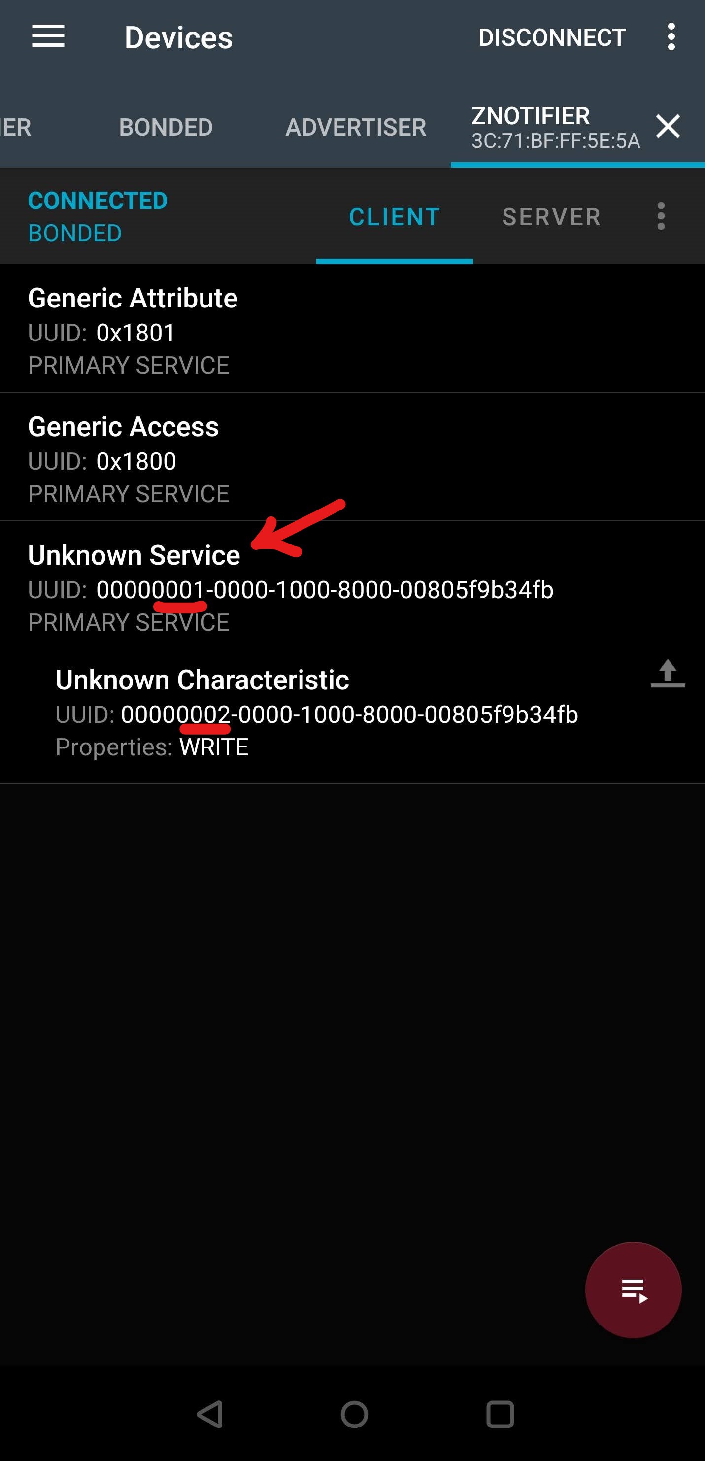
Using the nRF Connect app, I can write a string to the characteristic's value and see it update! This means that we can send the same strings as I tested before to activate the motors. See the screenshots below of this example working.
![]()
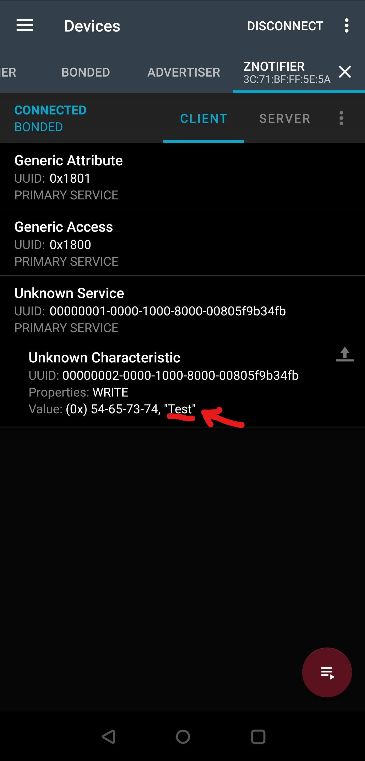
My service with UUID 0001, characteristic with UUID 0002 and the WRITE property enabled ![]()
Write the string "Test" to the characteristic value ![]()
Connected to nRF Connect app, the string "Test" is received and printed! So, now that I have verified that I can send strings to the ESP32 over BLE, I will be working on transferring all of the code over to Zerynth.
-
BLE testing with Zerynth
04/19/2020 at 18:47 • 0 commentsI'll include some Bluetooth terminology at the start of this log. I found these terms were the most helpful to know when implementing BLE.
GAP: Generic Access Profile, this profile controls connections and advertising in Bluetooth.
GATT: Generic Attribute Profile, this profile defines the way that two BLE devices transfer data back and forth using concepts called Services and Characteristics.
GATT Service: A GATT Service is a collection of characteristics that encapsulate the behavior of part of a device.
GATT Characteristic: A GATT Characteristic is a basic data element used to construct a GATT service. The characteristic contains a value as well as additional information and optional descriptors.
UUID: Universally unique identifier, each service is distinguished with a unique ID number.
To sum it up: GAP controls connections, and GATT is a way of specifying the transmission of data. The image below sums up the hierarchy of GATT very nicely:
![4. GATT (Services and Characteristics) - Getting Started with ...]() Here are the links for the Bluetooth documentation for GATT Services and GATT Characteristics. I used this documentation to see if there were any services that were applicable to the simple data transmission that is needed for the Haptic Sleeve. I found that all of the services were very specific, like Blood Pressure or Battery Service, so I ended up using my own service through specifying an arbitrary UUID that is not in the official GATT services. I will show this later in the log.
Here are the links for the Bluetooth documentation for GATT Services and GATT Characteristics. I used this documentation to see if there were any services that were applicable to the simple data transmission that is needed for the Haptic Sleeve. I found that all of the services were very specific, like Blood Pressure or Battery Service, so I ended up using my own service through specifying an arbitrary UUID that is not in the official GATT services. I will show this later in the log.Additional documentation for implementing BLE in Zerynth that was very helpful can be found here: ESP32 BLE Driver, Zerynth BLE Module.
Zerynth BLE Alerts example
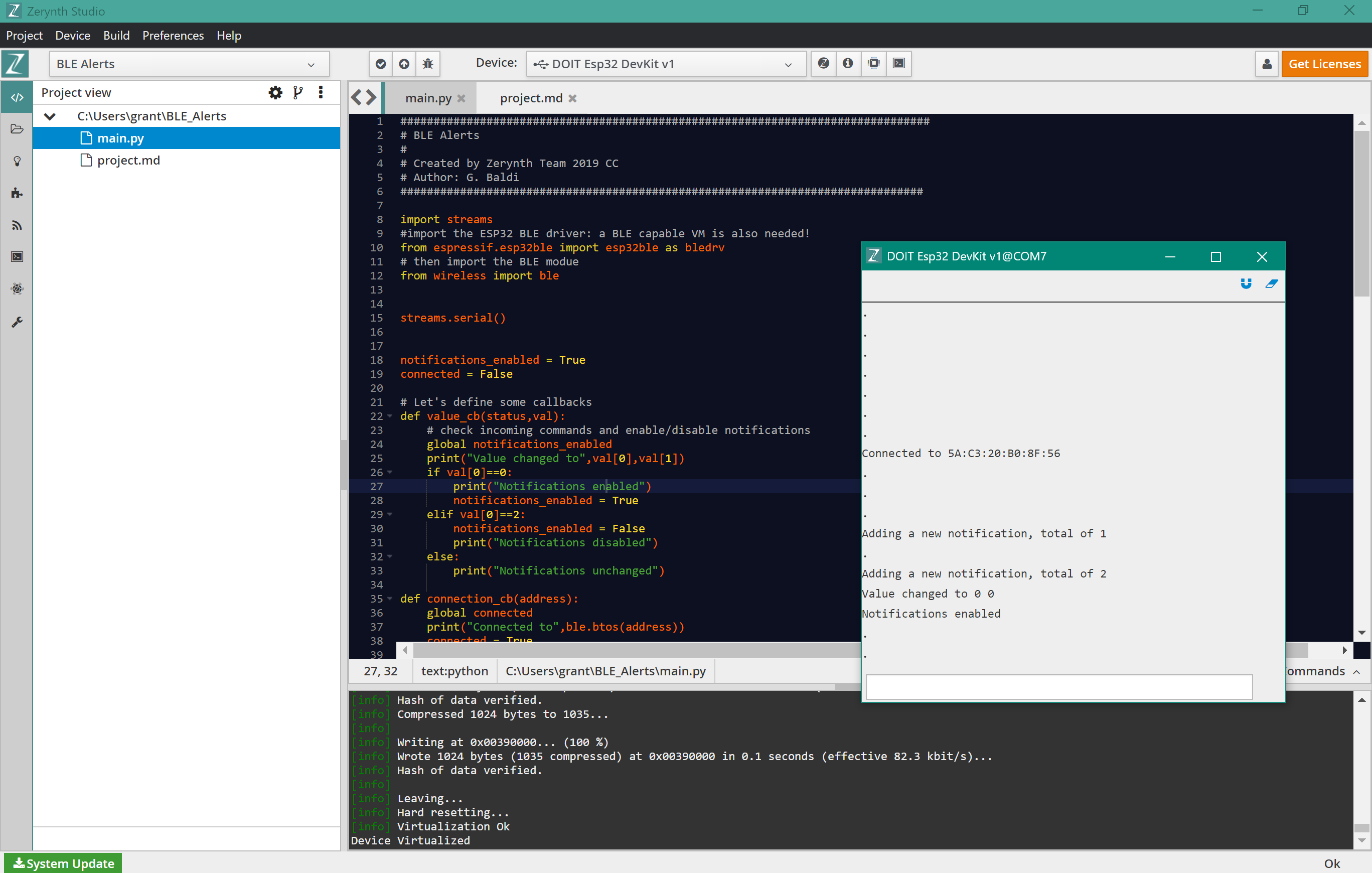
When moving over to Zerynth, I began with testing the BLE Alerts example that can be found within the Zerynth examples. All I had to do was clone the example, upload the script, and the initial test worked! The content of example isn't of much importance, I was only testing for a connection to the ESP32.
![]()
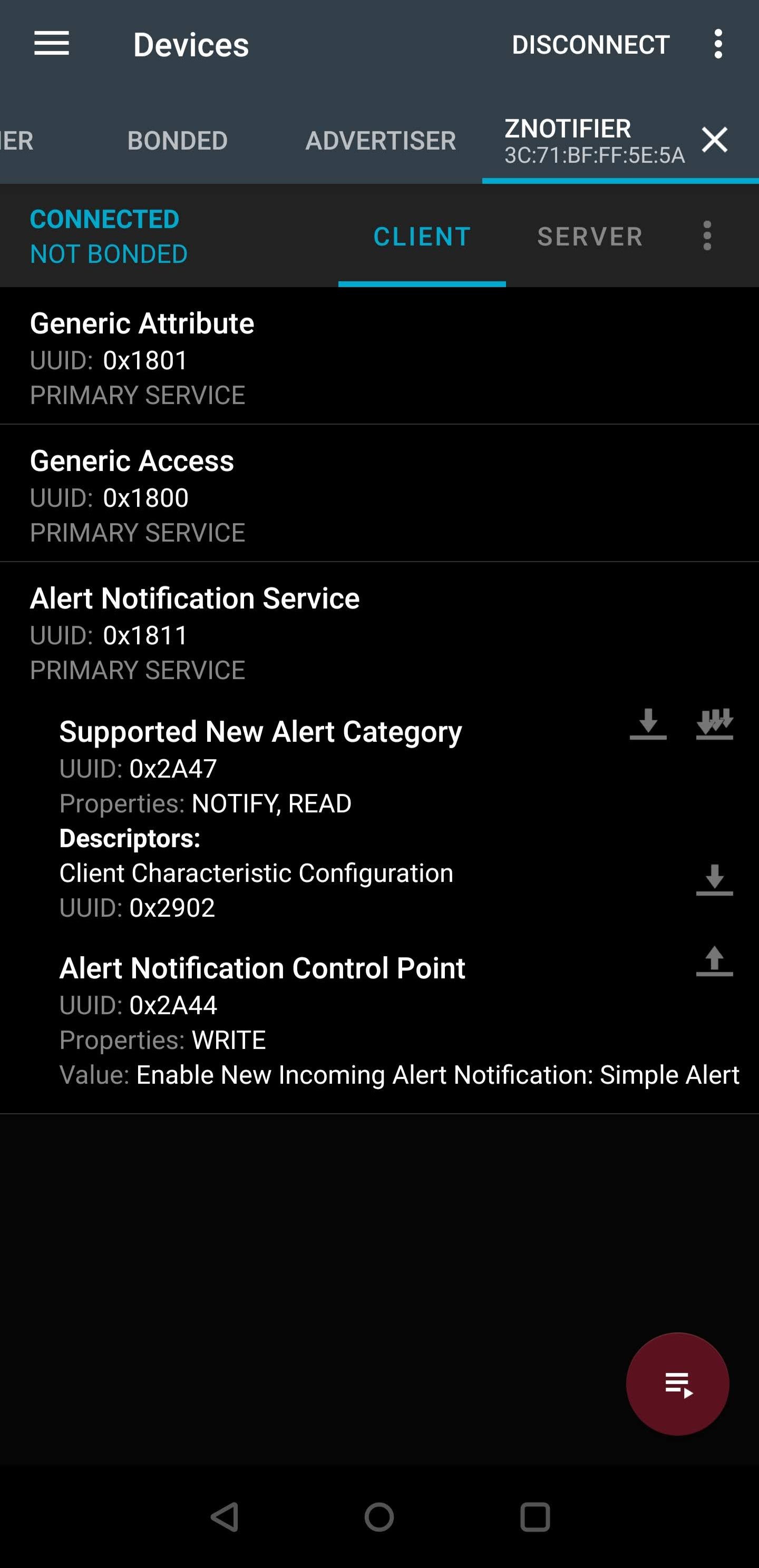
In the console window on the right-hand side, you can see the Bluetooth connection to my phone, then I sent a value from my phone to enable notifications. In the screenshot below, you can see the Alert Notification Service, and I modified the Alert Notification Control Point characteristic.
![]()
Secure BLE with passcode
The example that I tested above was not secure because there was no 'bond' between the devices. You can see this below, the ESP32 is 'Connected' but 'Not Bonded'.
![]()
Bluetooth pairing is different from bonding. Pairing is creating a temporary encryption between two devices, but bonding is the creation of permanent security between devices. Bonding is completed through the exchange of long-term keys.
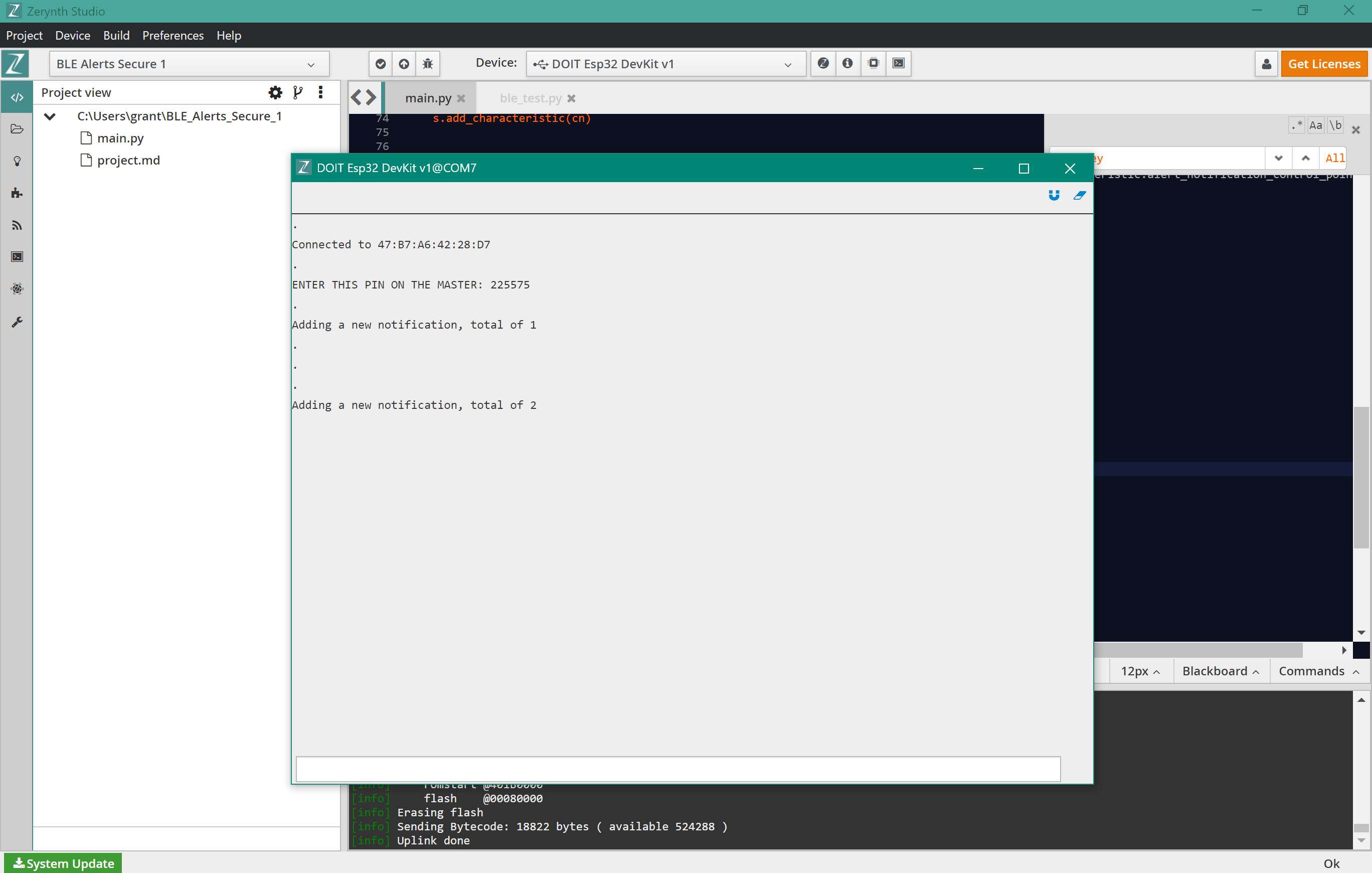
Since the Haptic Sleeve project only involves sending non-critical information over the BLE connection, bonding is not necessary, however having a secure connection is probably a nice feature to implement. So, I tested the BLE Alerts Secure example within Zerynth. In the screenshot below, you can see the ESP32 connecting to my phone then printing out a passcode to be entered. Success!
![]()
In my next log, I'll be detailing my process for finding a GATT service that will best fit this project.
-
BLE research and testing
04/13/2020 at 20:18 • 0 commentsIn this log I will be documenting my BLE research. On 4/8 I spent time researching BLE implementation in MicroPython for the ESP32. Through this research I was able to verify proper BLE implementation and communiccate with the ESP32 through an app!
One issue that I ran into was insufficient documentation for implementing BLE with MicroPython on the ESP32. I was able to find some examples that worked properly, but they were hard to find. It seems to me that not BLE with MicroPython on the ESP32 is not entirely common, so it requires building the BLE event handlers from scratch. Zerynth seems to have more support and well-documented examples, so I am currently exploring that route.
BLE background
Information about the basics of BLE can be found here. I found this link very helpful as I have never used BLE before. Here are the main points from BLE from that link:
"The different roles of a BLE device are:
- Broadcaster: a device that sends out Advertisements and does not receive packets or allow Connections from others.
- Observer: a device that listens to others sending out Advertising Packets, but does not initiate a Connection with the Advertising device.
- Central: a device that discovers and listens to other devices that are Advertising. A Central also has the capability of connecting to an Advertising device.
- Peripheral: a device that Advertises and accepts Connections from Central devices.
- Peripheral: a device that Advertises and accepts Connections from Central devices."
One device will be a central device, and another device will be a peripheral. The PC will be the central device so that it can discover (listens to Advertising devices) the ESP32 and send data to it. The ESP32 will be a peripheral device so that it can be discoverable (it Advertises) and receive commands from the central device.
The section labelled "Connections" is very useful and describes exactly how the two devices connect:
"Connections
In order for two BLE devices to connect to each other, the following needs to happen:- The Peripheral needs to start Advertising and send out Connectable Advertisement packets.
- The Central device needs to be Scanning for Advertisements while the Peripheral is Advertising.
- If the Central happens to be listening on an Advertising Channel that the Peripheral is Advertising on, then the Central device discovers the Peripheral and is able to read the Advertisement packet and all the necessary information in order to establish a Connection
- The Central then sends a Connection Request packet.
- The Central then sends a Connection Request packet
After that, the Connection is considered “created ”, but not yet “established ”. A Connection is considered “established ” once the device receives a packet from its peer device. After a Connection becomes established, the Central becomes known as the Master, and the Peripheral becomes known as the Slave. The Master is responsible for managing the Connection, controlling the Connection Parameters and the timing of the different events within a Connection"That's a lot of information! After reading it a few times, it started to make sense to me.
BLE test example
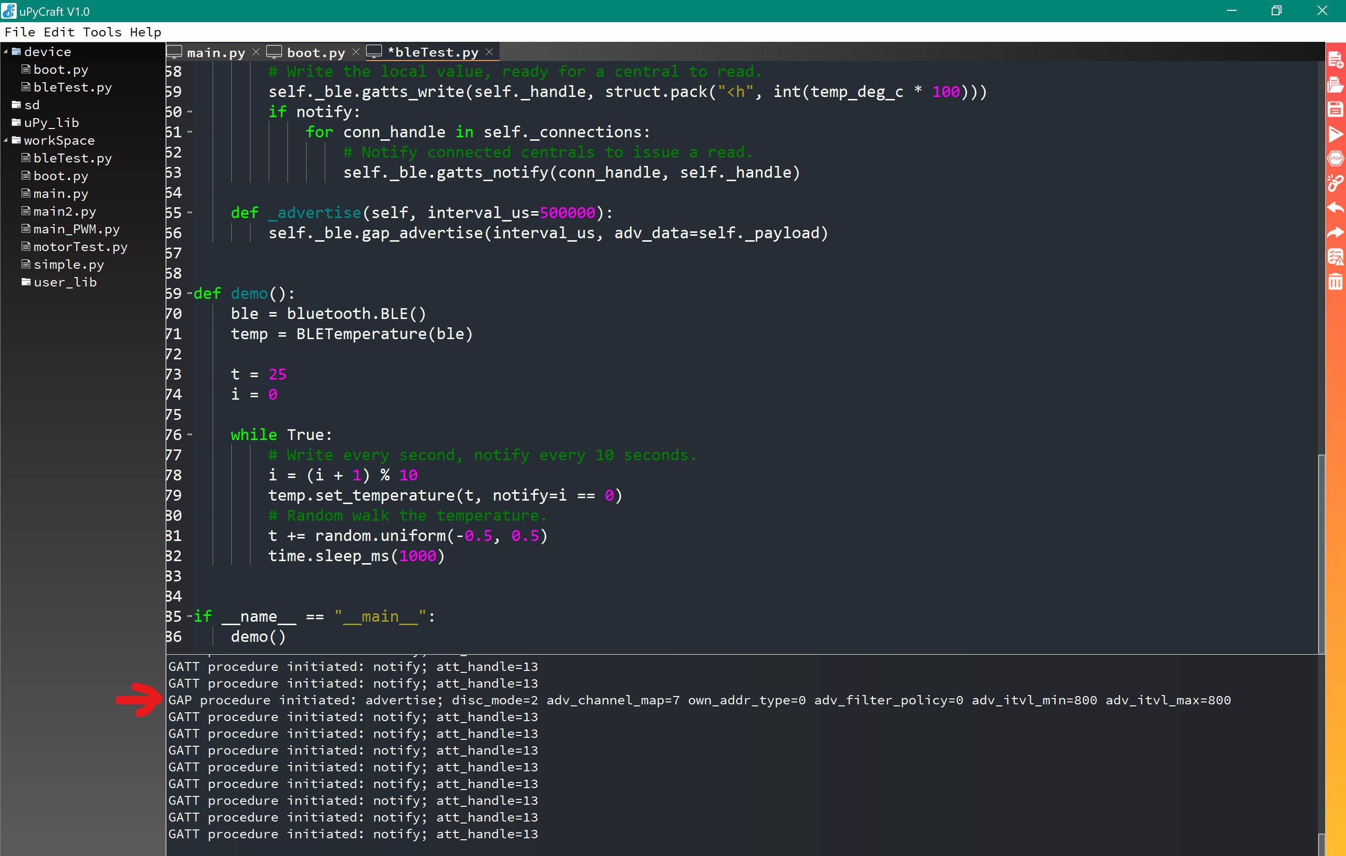
On the Micropython GitHub repository, there are BLE examples that can be used. I tested the example found here. In this example, the script generates a random temperature and publishes a random temperature value every 1 second.
To be able to view the values being broadcasted, downloaded a BLE scanning app. The app that I have been using is called nRF Connect, available for both iOS and Android devices. nRF Connect allows you to scan for available Bluetooth devices, connect to them, and see certain services that are being broadcasted.
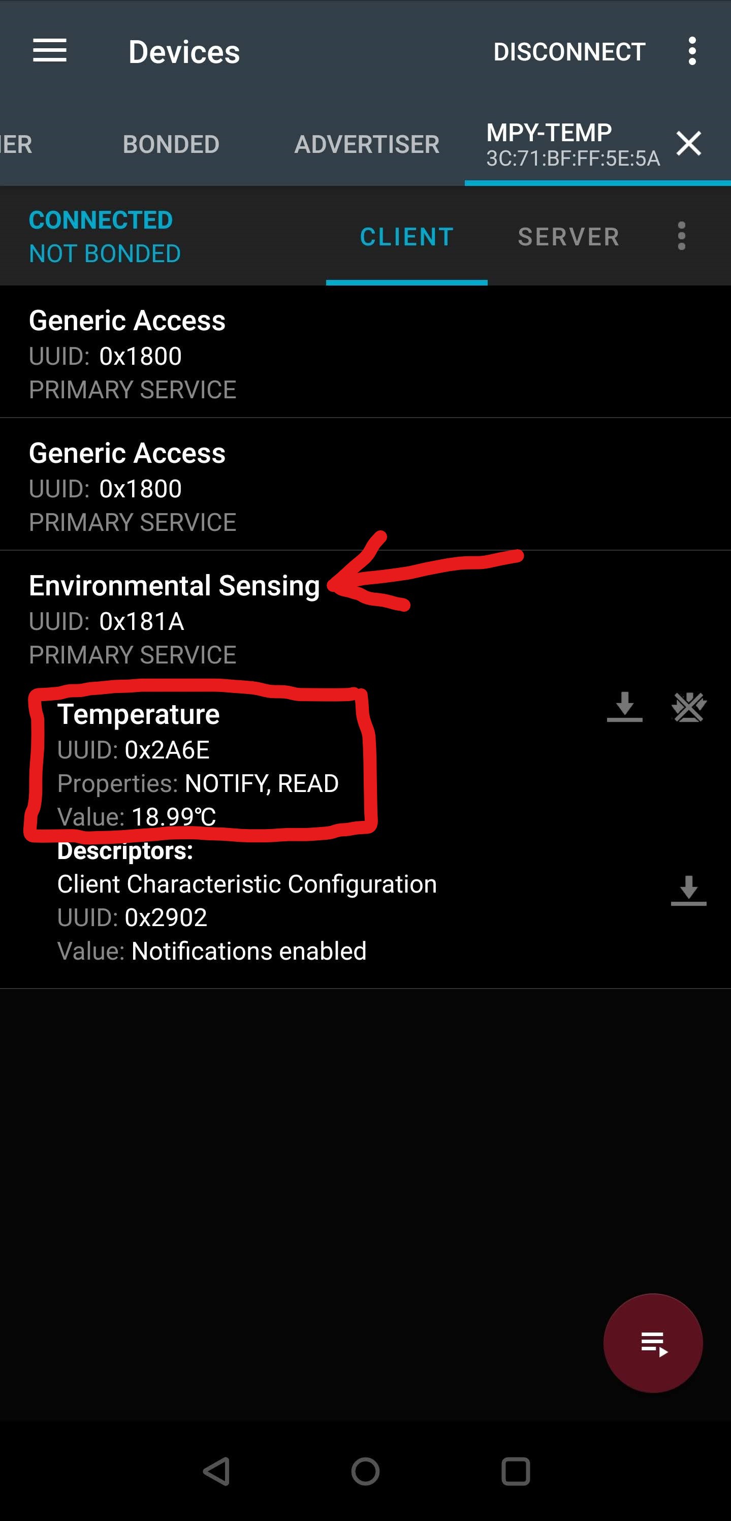
Below you can see my app connecting to the test script running on my ESP32 that is publishing a temperature value.
![]()
The test is broadcasting a service labelled "Environmental Sensing." That service can be expanded, and there is a field identified with the UUID (universally unique identifier) 0x2A6E, labelled "Temperature." This "Temperature" field has the properties of "READ," meaning read-only, and "NOTIFY," meaning to notify the connected device. It then has a "Value" field, which is where the ESP32 is updating the randomly generated temperature. The current temperature value stored there is 18.99C.
The nRF Connect app is very useful because it contains so much information about the connected device and the various program-specific services that are running on that device.
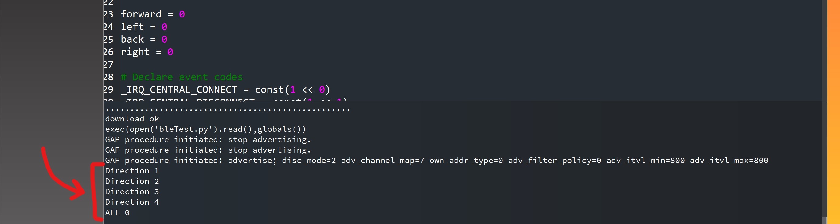
Below is a screenshot of the program running on the ESP32.
![]()
At the red arrow, you can see where the ESP32 connects to the nRF Connect app. The subsequent events printed are the notify events sent to the nRF Connect app. So the test program is working properly and sending values to the app!
My next steps with BLE are going to be sending values to the ESP32 from the nRF Connect app and exploring implementing BLE within Zerynth, since there is more documentation for Zerynth.
- Broadcaster: a device that sends out Advertisements and does not receive packets or allow Connections from others.
-
Haptic Sleeve schematics
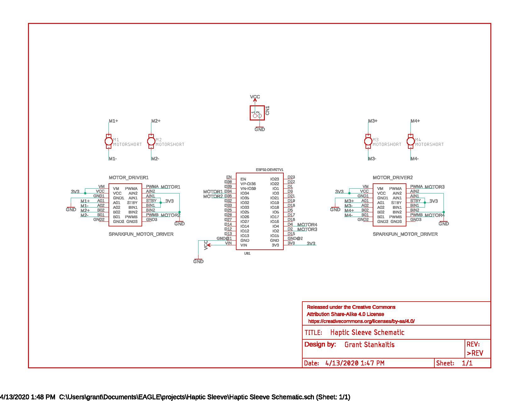
04/13/2020 at 19:22 • 0 commentsI'm going to combine the next few logs, so the dates will be in between each other. This log is covering the schematic and board design, and my next log is covering BLE implementation. On 4/5 and 4/11 I spent time completing the schematic and board layout for the Haptic Sleeve. Below is the completed schematic for the Haptic Sleeve.
The parts include:
- ESP32 DevKit v1
- 2 Sparkfun motor drivers
- 4 Adafruit vibrating motors
- 1 JST right-angle power connector, for connecting a battery pack
Some notes for my schematic design:
I had to spend some time designing the layout for the motor drivers with header pins since they were not included in the Eagle Sparkfun library. Additionally, I had to find a library that included the ESP32 DevKit v1, and I confirmed that the pins all line up and are properly labeled. Additionally, I had to modify the board design for the Adafruit vibrating motors because the silkscreen was unnecessarily large. I modified the layout to include just the necessary pads for connection. Once I sorted out these issues, the schematic and board layout came together nicely.
I included a JST power connector routed to the VIN pin on the ESP32 so that we can quickly connect up any type of battery pack with a JST connector (in my epxerience, JST connectors are a common connector).
I made sure to include mounting holes, so there are 4 holes at each corner of the board to facilitate board mounting in the final sleeve design.
Pads for the motors are labelled with the motor directions (front, back, left, right).
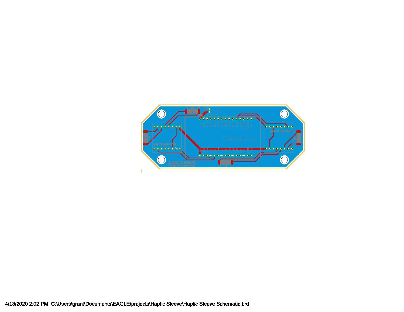
The bottom side of the board is a copper ground plane, and I was able to route all of the traces on the top side of the board.
![]()
Schematic ![]()
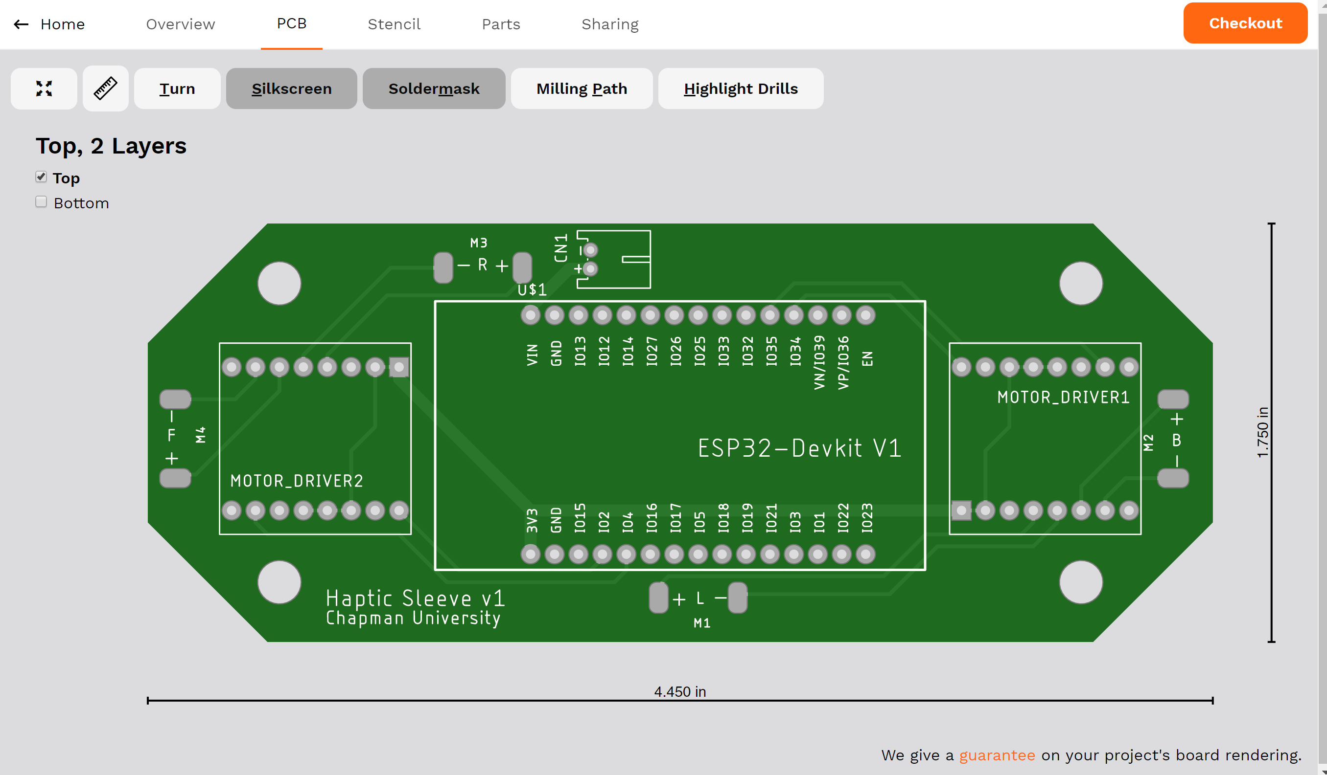
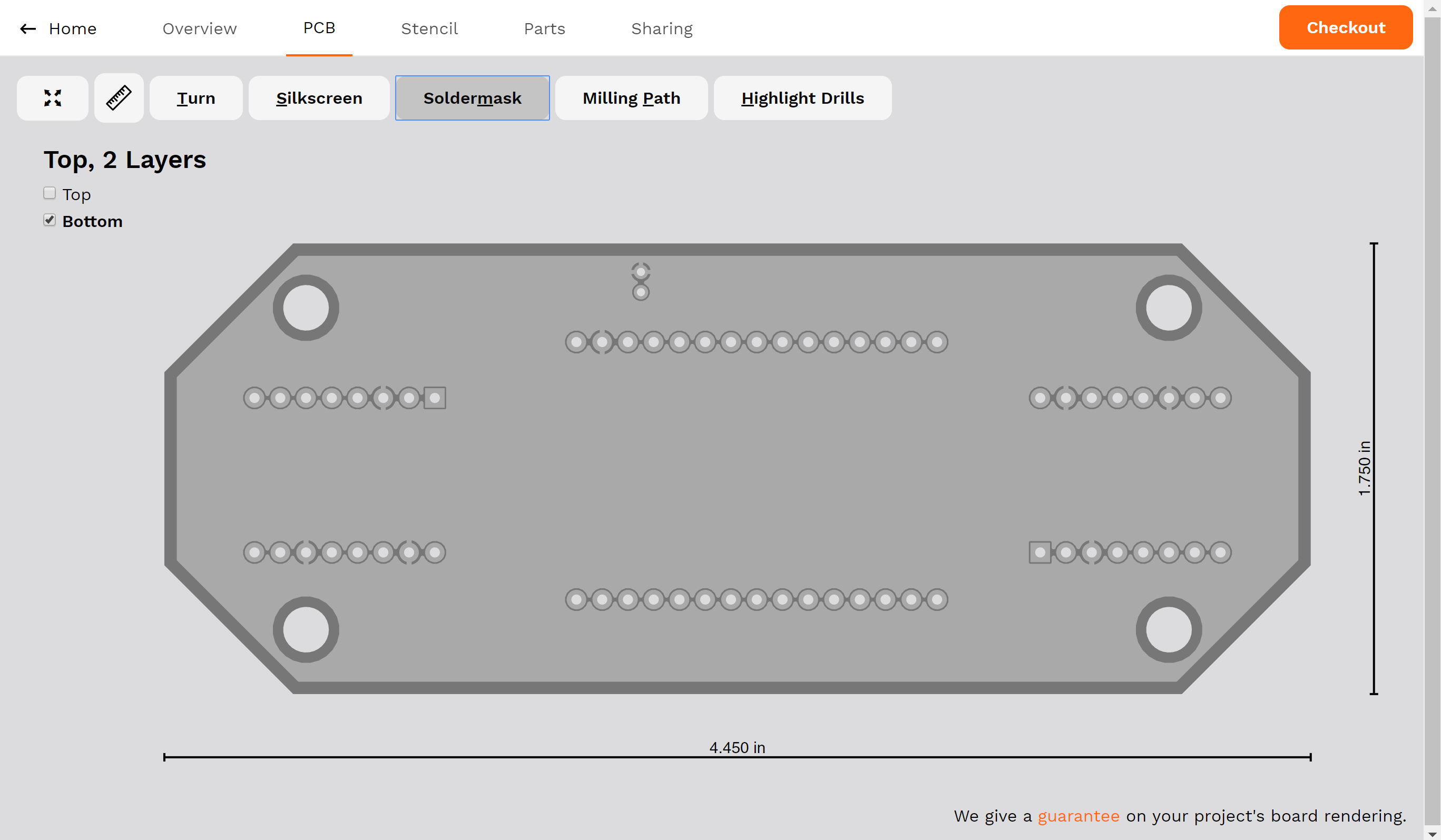
Board layout, red is top layer and blue is bottom Below are images of the PCB visualization through Aisler.
![]()
Top layer with soldermask ![]()
Bottom layer (soldermask isn't showing but it's there I ordered 3 PCBs through Aisler, with an expected shipping date of 4/16, so they should arrive by this weekend/early next week!
-
Activating motors with MQTT
04/13/2020 at 18:38 • 0 commentsI have been keeping track of my work for the past few weeks but neglected to keep my logs updated. So, here is my documentation for everything!
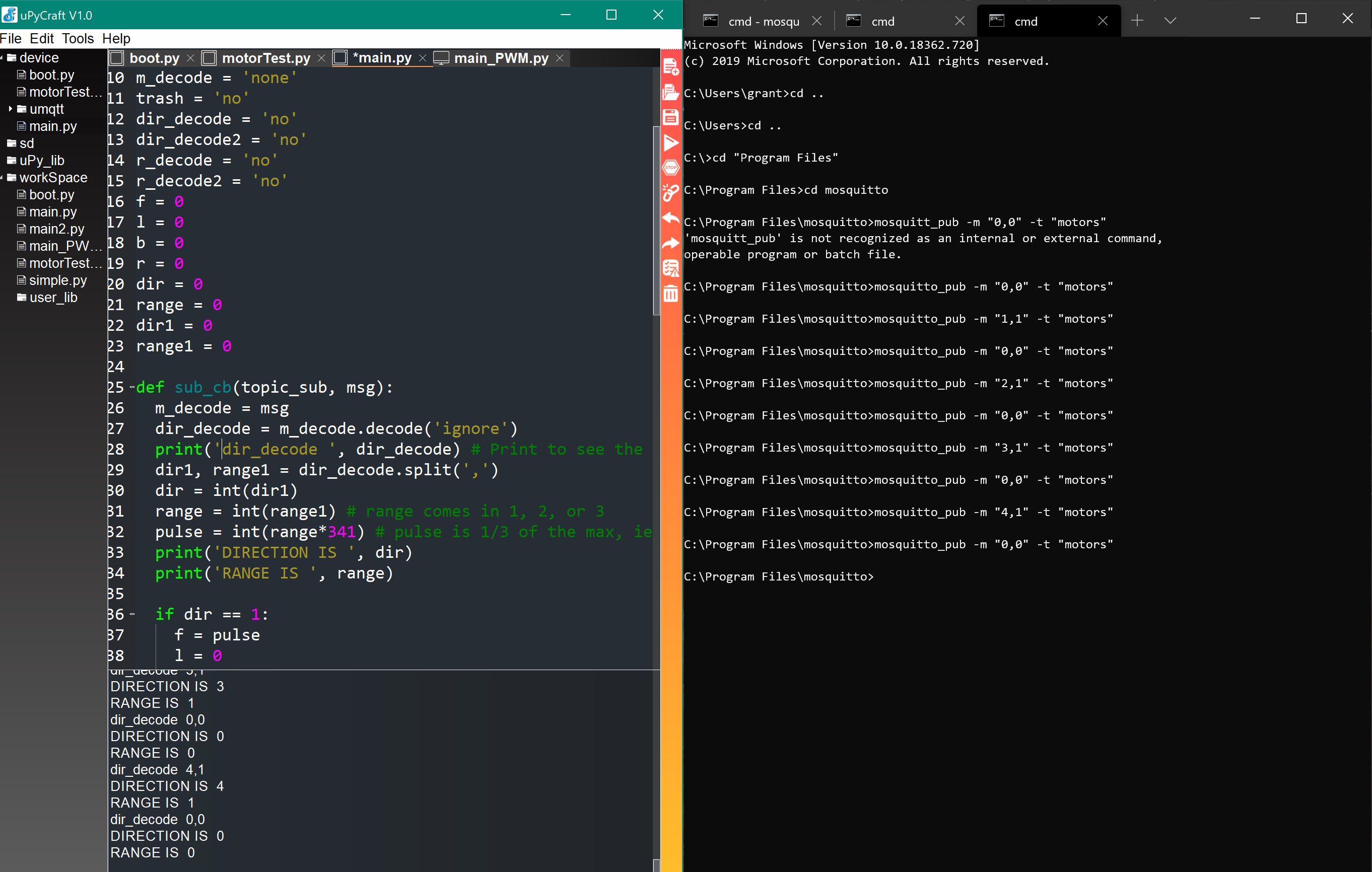
4/1, I was able to activate the motors using MQTT! I used the main_PWM.py script, sent messages from my PC to the server and it activated the appropriate motors with the appropriate PWM signal.
I did have to do a bit of debugging because there were issues with the code. The IDE was had issues due to inconsistencies within the file because sometimes spaces were used and other times tabs were used for whitespace. There were also important colons missing after elif/else statements, but after addressing all of these issues the code worked! See the screenshot below to see the command being sent on the right, and the ESP32 receiving the command on the bottom left.
![]()
As you can see, sending the command "0,0" turns the motors off. Then, sending a command such as "1,1" activates the 1st motor with a pulse level of 1. In the terminal window on the right, I tested each motor (1 through 4) with a power level of 1, and they all worked as intended. Additionally, not shown, I was able to test it with the specified power levels (1-3), and they all worked properly, being able to distinguish between the 3 power levels.
-
PWM motor testing (all motors)
03/30/2020 at 00:17 • 0 commentsAfter further testing, I can confirm that 2 motor drivers and all 4 motors work! See the video below to see all 4 motors vibrating sequentially.
Below is the code that I wrote to sequentially test all 4 motors:
import time
import machine
from machine import Pin

motor1 = machine.PWM(Pin(18))
motor2 = machine.PWM(Pin(19))
motor3 = machine.PWM(Pin(22))
motor4 = machine.PWM(Pin(23))

motor1.freq(1000)
motor2.freq(1000)
motor3.freq(1000)
motor4.freq(1000)

while True:
  motor1.duty(341) # Motor 1 on
  time.sleep(2)
  motor1.duty(0) # Motor 1 off
  time.sleep(2)
  motor2.duty(341) # Motor 2 on
  time.sleep(2)
  motor2.duty(0) # Motor 2 off
  time.sleep(2)
  motor3.duty(341) # Motor 3 on
  time.sleep(2)
  motor3.duty(0) # Motor 3 off
  time.sleep(2)
  motor4.duty(341) # Motor 4 on
  time.sleep(2)
  motor4.duty(0) # Motor 4 off
  time.sleep(2)
Now that I verified all 4 motors working, my next test will be sending messages via MQTT to the ESP32 to activate motors, simulating notifying the user of a deviation from the drawing path.
Haptic Sleeve
Sleeve worn on the arm to provide haptic feedback while performing handwriting exercises.

 Here are the links for the Bluetooth documentation for