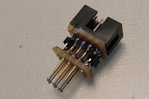
Insert a sturdy plate in between both (circuit board side) rows, fold over the longer side of pins, straighten down both bent rows with pliers and simply plug them in (fully, unlike in the picture where gaps have been left on purpose for visibility) over the central groove/channel, preferably starting on a breadboard row number ending in 1 to conveniently follow the existing labelling.
Be careful not to pull single pins from the plastic connector when reseating (should rarely be required) - at $2 or less, these weren't built to be unsoldered repeatedly either.
www.opencircuits.com/Solderless_protoboard seems to have had a similar idea using male headers to accommodate a ribbon cable.


 John Anderson
 Tom Dowad
 MaBe42
 Clovis Fritzen
Haha, I was just about to post something similar :) Yours turned out way better, though. One trick, I think, for the bending "plate" is to use proto-board that's been "snapped" along a row of holes. The half-holes are handy as they rest on the pins.