Pierre-Loup M.
-
About MIDI
04/13/2020 at 18:52 • 4 commentsAlthough not present on the original minimoog, midi is something so omnipresent and usefull I couldn't not implement it.
It happens it is quite easy to do with the Arduino environment, thanks to this library from FortySevenEffects. It's even easier with Teensy, has the library is automatically implemented when you choose MIDI as the kind of USB output.There are two "kinds" of midi on the synth. One is what is expected from a modern music instrument, i.e. the ability to interact with other instruments.
---------- more ----------This part is pretty straightforward for now : the synth appears as a MIDI USB device when connected on a computer (or anything where you can plug a MIDI device via USB). Key press, pitchbend and modulation are transmitted whenever they change, and can be received and processed by the synth as well.
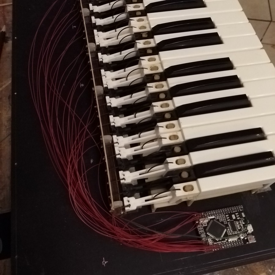
The second MIDI kind is the one used for communication between the Teensy that handles the audio processing, and the two Arduino Mega that read keyboard switches and potentiometers.
The keyboard is easy : the Arduino simply sends note on when a key is pressed, and note off when released. As the keybed used is not velocity sensitive, a default velocity of 64 has been chosen. The only thing to note is that the keys start at 0 (midi note 0, C-1), and they are offset in the Teensy part. It makes things easier to apply octave offset, among other things.
For controls, I tried to stick as much as possible to the midi specification. For some it's easy. For example MIDI defines CC1 as modulation wheel. CC5 is portamento time. Whenever it was possible, the official CC number was used to map functions sent from Arduinos to teensy. Most MIDI messages use a 7-bits value to send information. for some controls it's ok, but I had fear that for others it would not be a fine enough resolution. It happens that (probably) for this reason, the first 32 control change are 14 bits wide, with the 7 MSB sent on CC0-CC31, and the associate 7LSB sent on CC32-63. So some controls have been mapped to undefined CC in the 0-31 + 32-63 range. It's the case for both general and filter envelopes, filter cutoff frequency and resonance, the five mix knobs, to name a few. Attack and release often use CC73 & 72, filter cuttoff CC74. They have been assigned to CC59, 60 & 52, respectively.This poses a problem. Using the "official" control change numbers would have enable to simply map internal controls to external MIDI. Here is how it's done on Teensy :
- for note on messages, the internal handler handleInternalNoteOn() applies offsets to what is received from Mega 1, for the octave transpose, echoes this offset note to external MIDI OUT, and to the general function that also handles external MIDI IN, handleNoteOn().
- Same thing for note off.
- Same thing for pitchbend.
- Control change is only handled internally for now. Same principle could be applied, however as some controls have been remapped to others numbers, most of them should be handled separately. Because of the different CC number, and because of the different resolution. For now none are implemented from external MIDI, even those who have the number defined by the MIDI specification.
There is room for improvement here. As much as possible of the controls should be accessed through MIDI when connecting the synth to a computer or anything else, but having those numbers would mean having to handlers, and probably using setting functions for every control, capable of handling 14 and 7-bits wide ranges, instead of this unique handler with this looong switch/case statement.
It would also open the door to something usefull : the ability to save and recall presets.Two websites have been used for checking which CC numbers to use :
-
About pitchbend and modulation wheel
03/31/2020 at 22:23 • 0 commentsThe two wheels are importants components of this project. And it took time to figure out how to make them.
The first and most obvious idea was to 3D-print them. Or at least the bracket. For the wheel itself I wanted something else, as the final aspect of 3D-printed part is not so good, unless you spend a lot of time with abrasive paper and primer, and paint, and...
So, 3D-printing. If my printer were perfectly tuned, it would have been a two-hours story, designing the part, slicing it and printing it. But its not. The first part broke when I remove it from the printer bed, the second exploded when I tried to put screws in it, so after a few missed attempts I came back to what I know : acrylic and laser cutter.
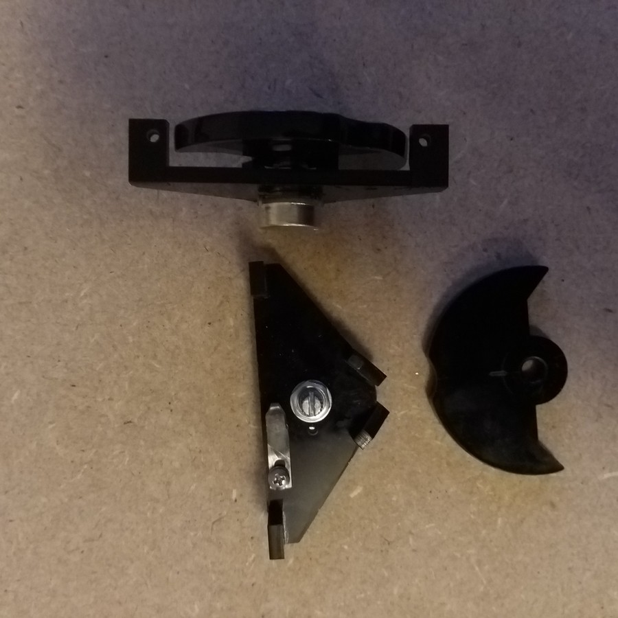
---------- more ----------The final version of the bracket is made of five parts of 4mm thick black cast PMMA. The laser cutter gives slightly beveled edges, so a bit of filing was needed before assembly. The five parts are fitted together, then glued (in fact chemically soldered) with chloroforme. PMMA cement can also be used.
![]()
The wheel assembly, complete.
For the wheel itself, I had several ideas. Wheels on modern synths are beautiful, some with white flange, other with clear plastic and light underneath, with a silicone revetment on top... beautiful but too modern-looking. I thank about a pmma flange (not visible) and a wooden rim. And finally opted to all-acrylic. They are laser-cut too, in 6mm black PMMA. The rim has been sanded to remove the cutting marks and give a slightly rounded profile. Then the miracle technique : a small blowtorch is passed along the edge, which gives a perfect finish in ten seconds. Ok, I've made an extra one to have the right move, but it's really efficient.
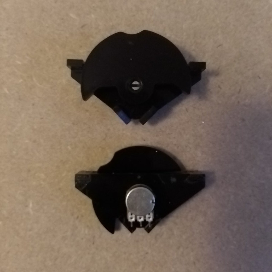
The wheels have a small groove, and the pitchbend assembly has a spring that notch into this groove, so neutral can be felt. The spring has been made with 0.5mm spring steel, and is simply screwed onto the bracket ; the hole is oblong, so the spring can me moved to precisely position the mid-point.
And then, how to mount the wheel on the potentiometer ? The hole is laser-cut , I've simply let the blowtorch burn a few seconds on each side, through the hole, then press the wheel on the potentiometer axle. It's perfectly adjust, can me removed if needed, and there is no play. Simple and easy. I just realised I could have mounted the potentiometer into the mandrel of my drill press to have a perfectly right fitting. Net time... :)
![]()
-
Making a nice body for an iconic synth
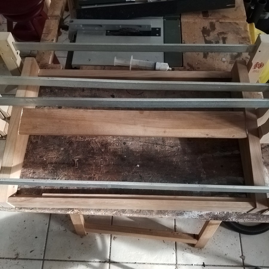
03/31/2020 at 20:04 • 0 commentsThere were Initially no plans made for the body. I simply cut a sheet of 10mm plywood, and placed the keybed on it. Then try to figure out the placement of all components. Taking a measure, cut a part, put it on the synth, and so on.
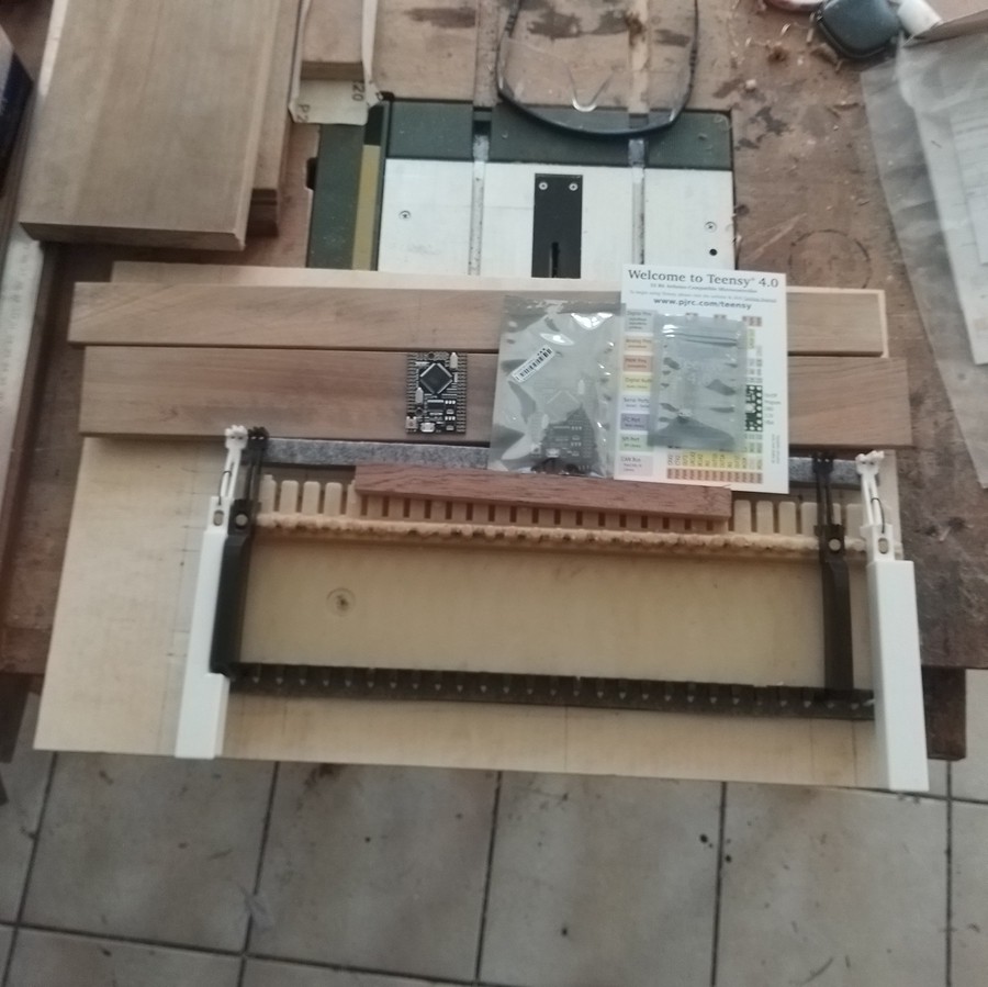
The wood is wallnut, from an old dining table found on the roadside... For two years I really believed I would repair and use it ! :DThe parts have been cut to length, placed on the plywood bottom, then adjusted following the keybed shape and size.
![]() ---------- more ----------
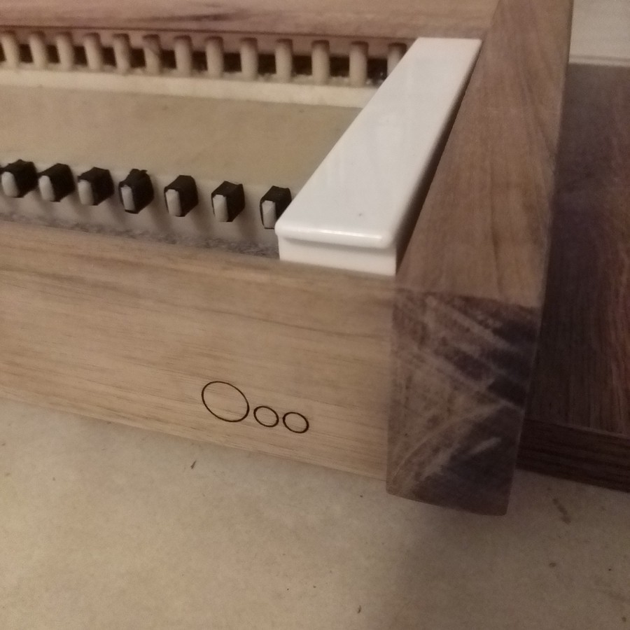
---------- more ----------The mark on the front and rear spar is laser-engraved.
![]()
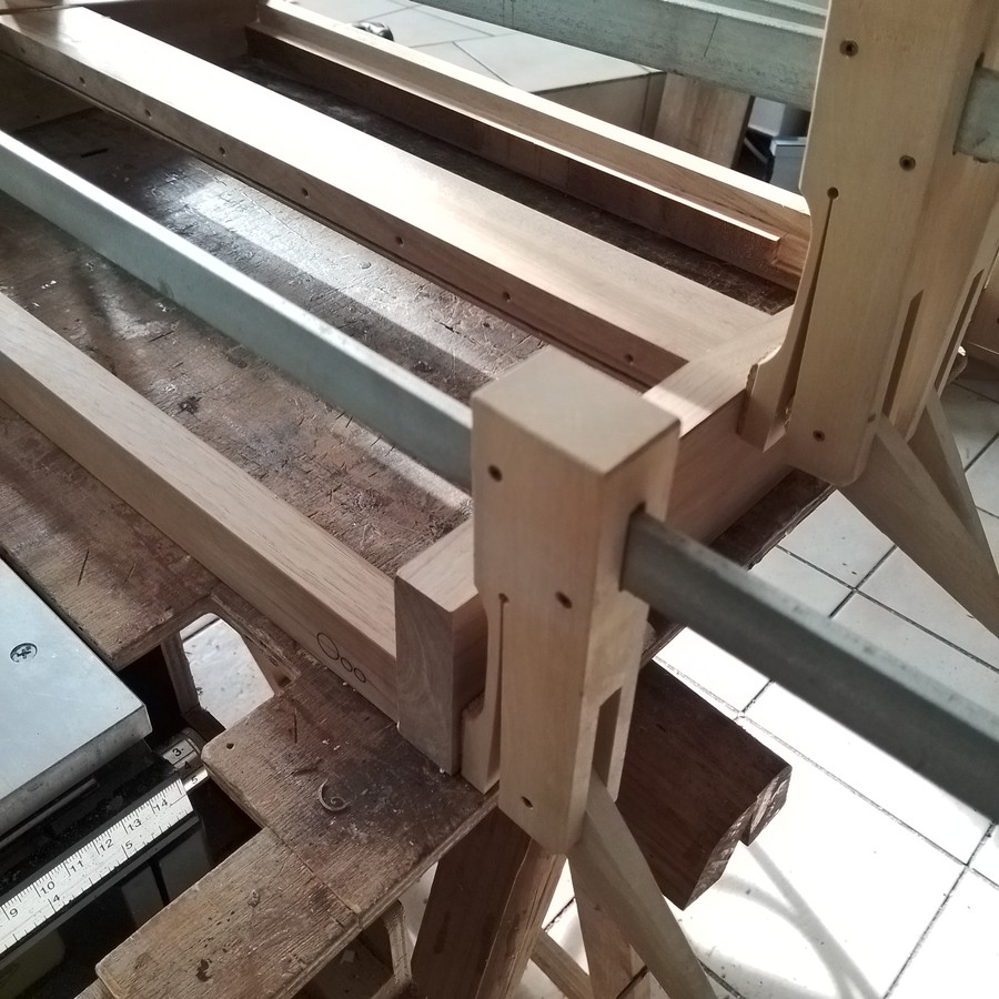
The front and rear spar, and the sides, have a 10x10mm rebate. The bottom panel comes and is screwed into this form. All the parts are glued together with wood white glue ; the front, top and rear spar being held on the sides with a mortise and tenon joint.
![]()
![]()
Here we see the holes for the screws holing the piano hinge for the front panel.
The wallnut parts have been finished with tung oil. I really love this, but it takes time...
The rear spar was initially straight, but I had to modify it, there was not enough room for any connector between it and the front panel... :/
The front panel is held by two spars. The front one is screwed on the piano hinge. Both have a groove, in which the front panel simply slides. Everything is held in place by the back of the front panel, which is screwed behind on the two spars.
I'm sorry I didn't took that much pictures when doing it, but things will be more obvious if you have a look at the drawings !
A note about these drawings : They represent what I made, but should you do one, you will have to adapt to your keybed. In any case, I was constrained by the pieces of wood I had. The synth sides should have at least 20mm more in height : every mm is counted in the front panel, the pins of the selectors had to be bent so it can be closed. And I don't even know how I will put a support for holding the front panel up. That would make more room for the plugs on the back, too.
It should also have at least 30mm more in length, so the spars are not grooved to let room to the rotary selectors.
Width could be a bit large too, the pitchbend and modulation wheel potentiometers axles had to be shorten to feet between the keybed and left side body ! -
Panels.
03/30/2020 at 17:56 • 0 commentsAll panels of the synth are made out of acrylic sheet. I believe other materials would be nicer, but it happens I use 4, 6mm cast acrylic, and 2mm extruded acrylic sheets for work, thus having plenty at hand.
And as I'm lucky enough to also have a laser cutter, it became an obvious choice to use acrylic, that I can both cut and engrave in one go.
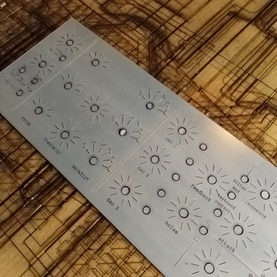
The front panel, despite its simple appearance, took time to design. It had to be decided all the function wanted, were to place them, take attention to the room around switches and potentiometers (for moving them AND regarding their own size).
Then space them evenly, and check... to move them once again, because something was missing... A game of try and error. :)
I also used a scrap piece of acrylic to place buttons on it to have a real idea of how it would be, and check distances.![]()
There is some dust here...
---------- more ----------
I mainly use Catia V5 for everything I need to design. The panel has been drawn in Catia, then a layout exported to DXF. The graduations for pots, waveforms, texts, separations are made using InkScape (which has powerfull tools for spacing shapes). In fact it could be design with InkScape alone. The file is then exported to DXF again, and the laser G-code generated using CamBam (which, despite its Windows 95 look, is a great tool too !)
I wanted to have more controls on the panel, but the keybed dictate its size, as well as the available inputs on the Arduino Mega. I wanted to have reverberation and / or delay, but not enough room. And as it's now, every single ADC on both Arduino is used.
![]()
This is the first panel, I then realized some things had to be moved, other added...
Once the panel cut-out, engravings have been filed with white paint. it's quite straightforward : a lot of paint is put on, then the excess is wiped out.
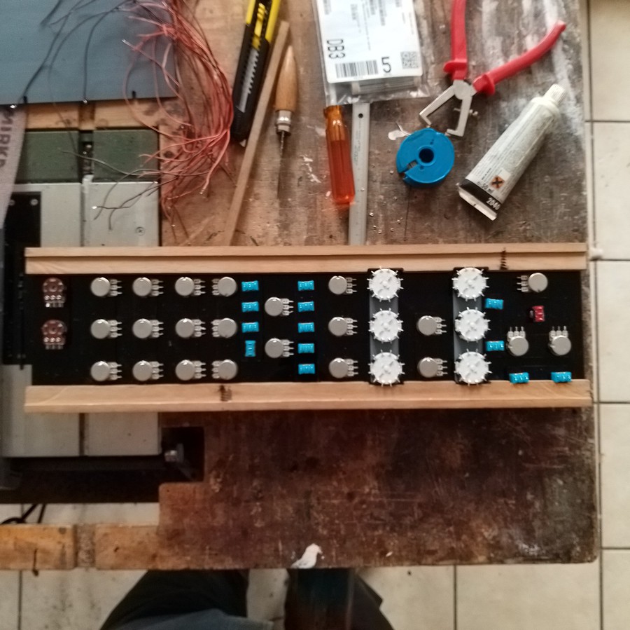
The controls have all been mounted on the panel. They are mounted with shims, to compensate for the switches, potentiometer and selectors height, to have the controls at the panel level.
![]()
Potentiometer are all 10k linear, except one (two on the picture) for output and headphone levels, which are logarithmic ones. (Side note : it needs an amplifier to buffer the phatDAC output, which I don't have yet. Don't even know what to use !)
They are all wired to their respective ADC on one or the other board.
Switches are all two position ON-ON, except the one for octave control which is a temporary three position (ON)-OFF-(ON). They are wired one pin to digital inputs of Arduinos, the other to GND. Every switch uses internal pull-up resistors of the Atmega.
Rotary selectors are connected to ADCs. Their first pin (position 1) is grounded, the last pin (position 6) is tied to VCC, and a resistor ladder is soldered on the pins in between, so the output is stepped evenly between 0 and 5V, and only one pin of the Arduino is needed per selector. The wiring is also a lot simpler compared to what it would be with digital pins.
Note : I may draw a general wiring schematic, but all connections are listed in their respective sketch, and the github repository has a file listing controls, and two for front and side panel connectors.
![]()
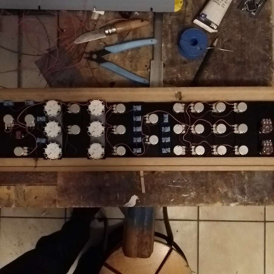
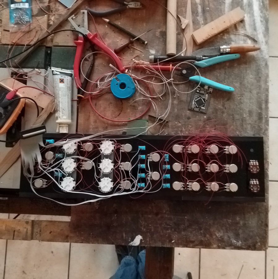
I started by wiring everything to ground, then VCC (which is 5V here). I didn't really think about how it should be done. I've taken care not to create loops, but it has been wired as it came.
The last step is to wire all the signals. I used a 34-wire ribbon cable from an old computer, which connected perfectly with a shorten Raspberry Pi GPIO connector. And it was long enough so I could reach everything in the panel with the connector mounted on one side. So...![]()
Now it starts to be a mess !
The second Arduino Mega is mounted on the rear side of the front panel, with double-sided tape.
The panel is held close by screws holding the back, but I'll come back to it later. On the picture is may be seen some marks on the wooden parts on top and bottom of the long side : there were the screws holding the plate on its frame, as the wood is coming from an old table... ;)
-
Starting to build a synth !
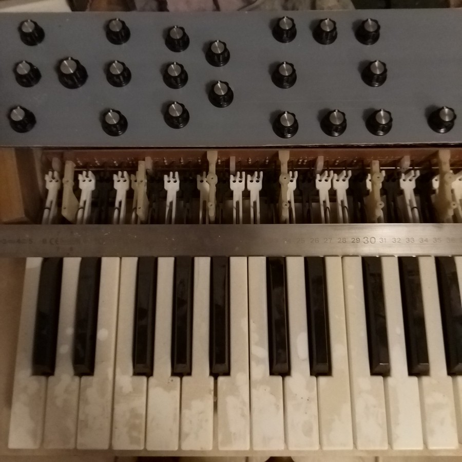
03/29/2020 at 22:19 • 1 commentThe most obvious part for a synth with a keyboard is... a keyboard. Or a keybed, since it's the name the key assembly is called (thank to Tim Trzepacz for mentioning it on his inspiring NanoEgg project ! Funny how having the right word can save so much time when looking for something around Internet !).
The one that was used comes from an electric all-pastic organ made by Bontempi somewhere around the mid 80's. I found it at a secondhand market, not working, for almost nothing.
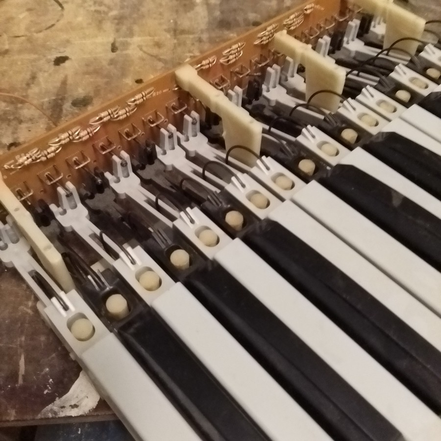
The construction is quite basic, with a plastic rack with mounting holes underneath (one less thing to think about !) each key being mounted on a pole and held by a circular spring. This rack has brackets holding a pcb the size of he keybed, on which were something looking like a resistor array. I wondered for a time if i was going to try and understand how it worked, but eventually just kept the PCB to route my own wiring.Each key has a smooth spring attached on it, which is soldered to the pcb. These springs come to touch a metal rod when the key is pressed. (note : the keybed was one third grey with these C-shape contacts, and two thirds white with a unique rod going all the length. The synth uses the white keys with the rod.)
![]() ---------- more ----------
---------- more ----------
The pcb has been cut several times as the project progressed. The first time in two, to separate the grey side from the white side. It was then cut again to limit the height of the keybed, just at the level of the brackets holding it. But is was yet too high, so the brackets were cut, and the pcb finally mounted on a wooden support on the synth base plate.
The pcb has been kept only because the contact springs are soldered on it. Each contact has been wired to a digital input of the first Arduino mega (exact list in the sketch mega1), using internal pull-up resistors ; the long rod on which they come to contact is grounded.![]()
The keybed was quite noisy when pushing and releasing keys, so I added two thick pieces of felt running under the keys. One at the front, to dampen the key at the end of its travel, one at the rear, on which it lies when not pressed, which also dampens when it's released.
On a software side, with springs as switches the need for debouncing becomes even more important than it usually is ! There are plenty of libraries out there, I've used one I wrote years ago, which works well.
Keys are wired to consecutive inputs, so the main program only defines a table of PushButton objects, one for loop in setup() to init each key (input mode, associated pin and debounce time), then one for loop in the main loop which updates the key and sends a MIDI message on change. The keys are mapped to midi notes from 0 to 29 ; offsets are applied on Teensy side, which was easier when testing code : programming this Mega board means removing everything ! -
First record !
03/23/2020 at 02:15 • 0 commentsFirst project using Teensymoog !
Everything made with the synth, except the drums.