MasterOfNull
-
Assembly and merge conflicts. :)
05/29/2020 at 07:22 • 0 commentsAttempted to assemble the latest revision of the hardware. Most things 'worked'.
I had no hope of it actually turning on here as I know I did not properly implement what @Steven.Carr had changed for the backend. I had merge conflicts which I did not resolve and he is ahead of me.
So here is the no net, back of my head, unpublished, unedited version of that experience. Be kind..
We did learn some things from this. We are implementing them. -
Minutiae
05/18/2020 at 07:29 • 0 commentsFirst off, using individual jumpers sucks. This choice alone has probably cost me 20 hours of debugging time. Some pin header ceases to fit perfectly and you partially lose ground, which makes things fail only when the majority of signals are above the halfway point between ground and Vcc as the the low going pulses also provide a partial ground. Argh.
Narrowing this down to the jumpers happened when everything finally got hand soldered directly, and all the strange issues happening during testing just went away.
Hand soldering wires still also sucks though. So I have now specified pre-made IDC connectors and matching keyed sockets for all the internal connections.
I have also settled on using an RJ45 connection to our current #VISP - Ventilator Inline Sensor Package module which uses dual I2C, by splitting the four pairs of wires of the Cat 5.
One leg of the each of the four twisted pairs will run SDA1,SDC1,SDA2,SDC2 and the other half of those four pairs will run our Vcc/ground. This seems to be a reliable way to get what we need for running dual I2C channels, out of an existing and robust connection like RJ45. Much more so than trying to run the SDA/SCA on a single twisted pair anyway, as they essentially work against each other then as they are not intended to be halfsies of a differential signal. :)
This also probably means generating two tiny daughterboards just to make our IDC to RJ45 jack connection, and to plug into our new optical interrupters, but so be it. Reliability is kinda key here. Which leads me into the next design choice.
Using unshielded hall effect sensors anywhere near a DC or stepper motor, unless they were designed for that particular motor, also sucks.
They will read perfectly, until you start your motor (if you are lucky). If you are not lucky, they may still read perfectly.. for a while. Eventually though it seems they reach some saturation or auto-leveling point, and cease to work reliably until you remove the field generated by the motor/stepper.
Our hall effect sensor for detecting 'home' got replaced by optical gates and a laser cut encoder. I also attempted to future proof this bit by adding a second encoder we could use to read the rotational rate. That led to four more design variations on how to space the encoders/encoder slots. I have arrived at the final revision for this.
I've built out a single glue board for hooking all of this up. Assembly and testing will happen tonight, if I don't run out of steam.
-
Full stack developer
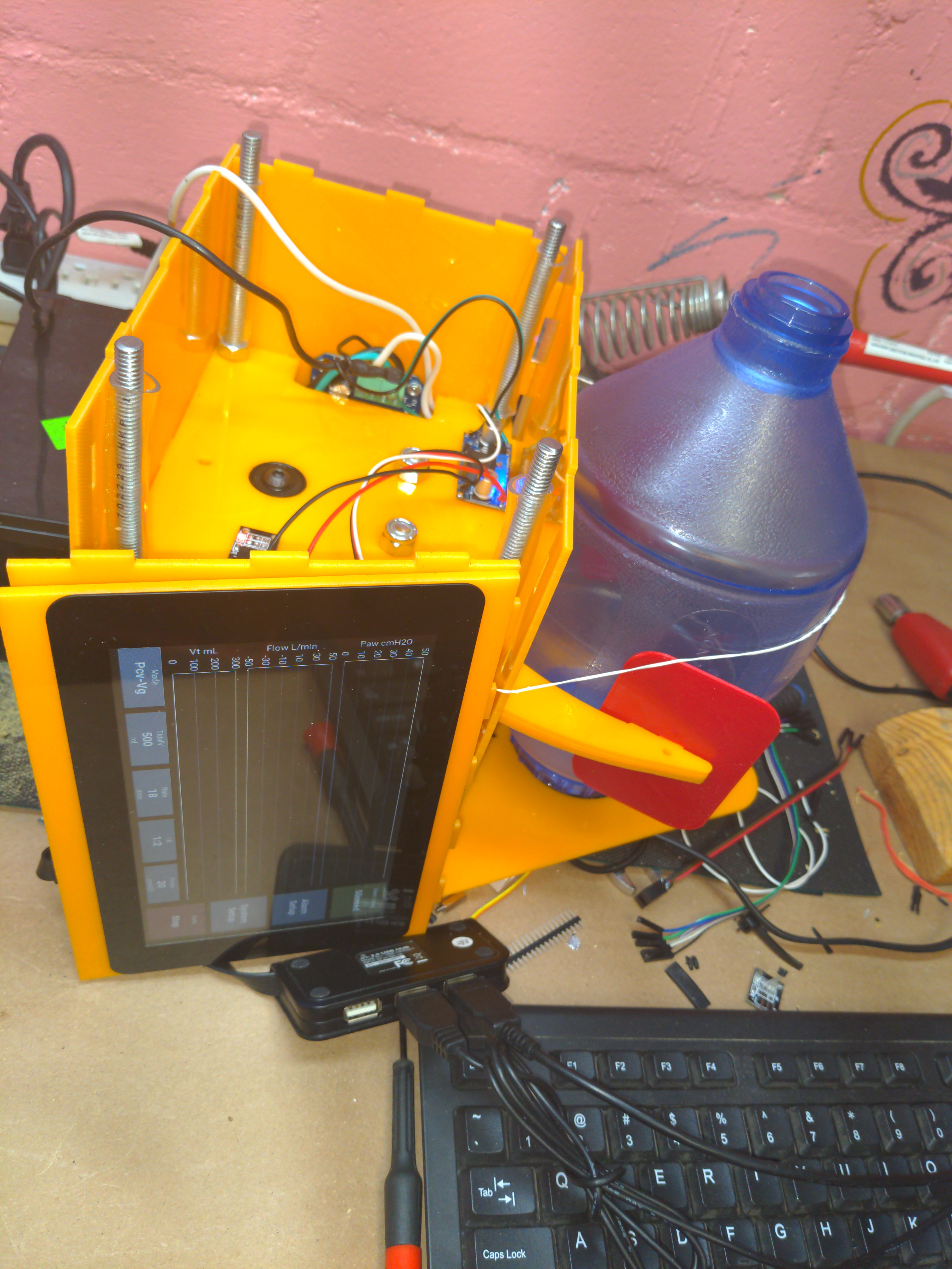
05/14/2020 at 11:44 • 0 commentsAssembly using the 'all at once' mantra was very annoying.
The front and rear are now split into panels held together by screws. This means you can assemble all the mechanical bits, and then assemble all the electrical bits. The latter I'm shooting for four screw terminals and two ribbon cables. Time will tell.
Mounting the Pi touchscreen needed a couple layers...
A whole new category of full stack developer. :)
-
Hand wiring really sucks.
05/14/2020 at 05:00 • 0 commentsI finished up the latest version of the acrylic tab/slot version and promptly set about manually wiring up my control panel for it. Looks good right?
Several hours later I realized how much this sucks. There is absolutely zero chance anyone not in a third world country who desperately needs this, and has no other choice, would do this for 1000 units. This issue could be fixed with a suitably large PCB I could through-hole, but that also sucks.
I promptly put that idea on the back burner and decided to stick our other display (Pi touchscreen) directly on the unit.
It still uses the serial protocol @Steven.Carr came up with to interface between the critical code running on the 'core' and the Pi. This means we could still split the two and use some wireless protocol instead... or run it on a tablet, or have it go away altogether and the core will just keep truckin..
![]()
This also led to the discovery that wiring this thing up and *then* assembling it also sucks hard core.
I am in the process of redesigning the front/back panels so they can be now removed without having to split the case. This will translate to the ability to assemble the entire unit, plug stuff in, and then put the front/back on as the last step. That is going to waste some material, but it will save a whole buttload of time. Everything goes together pretty quickly, right up until you start getting wires caught in the tabs and such.
The time lost is far more valuable than the material in this case. Doing it.
-
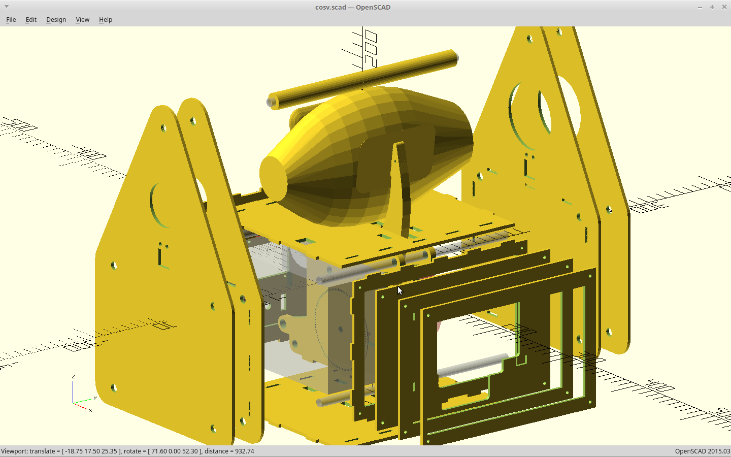
Everything is on a cob
05/10/2020 at 10:09 • 0 commentsAnd it has been terrifying. A whole lot in the physical design has changed, very quickly.
In fact, the overall goal of the project, has changed
We started out using the American version of the design requirements document. which specified a 1.5s breath interval.
That varied greatly from the later released UK ventilator design document. That actually seemed a lot more sane and specifies a 0.3s inhale timing. Switching documents resulted in a five fold increase in our power requirement.
That five fold increase now puts our drive system requirement coming in between 30W and 60W.
Finding a capable motor that can do that for 400k cycles without breaking a sweat increased the weight of the drive section beyond where it was feasible to place this unit on the patient.
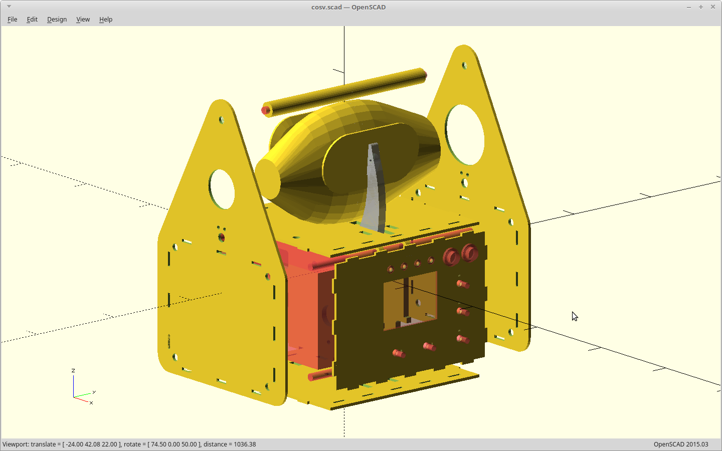
Since we are now moving beyond our strict weight limit, I also decided to add a battery backup.
That led to designing a better body to house all of our new toys.
I decided to go all-in on an interlocking pin/slot panel design. The new body and battery meant we now had a transportation ventilator on our hands here, so it got a handle. This meant we needed to move all of our controls and cable connections to where they are less likely to get knocked around when this gets tossed into an ambulance.
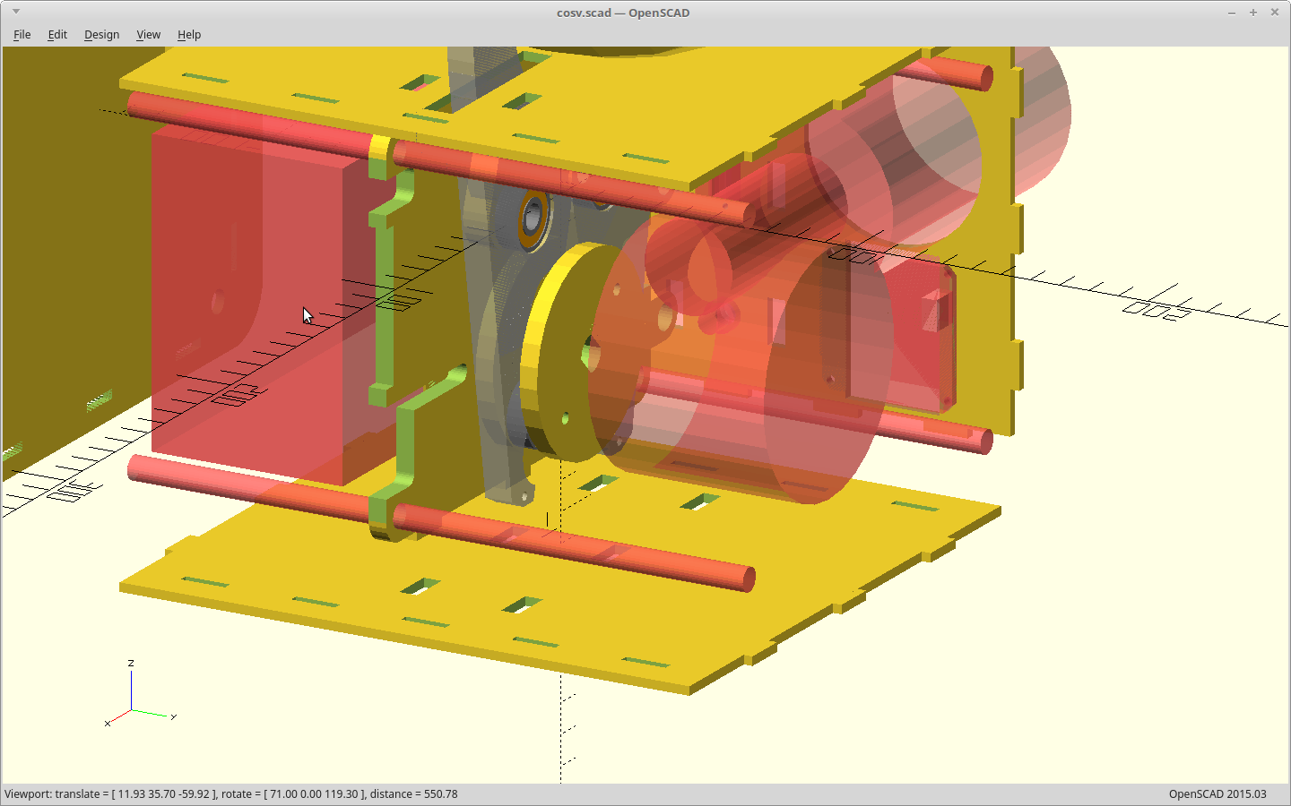
Next step of adding an extension hose to the ventilator bag, and then kinking it off with the pressure release disabled just to see what happened, resulted in us shattering the cam. We have power to spare here.
The cam got redesigned as a solid disc, and the cam arms now clear the disc on either side.
If we were to suddenly lose our active feedback for volume/pressure, we decided it would be best to alarm, but still keep doing what we were doing. To do that it is probably necessary to add an encoder to our dumb motor, so we actually know how hard/fast we are pushing. We added an encoder and a spot to put our reader for it.
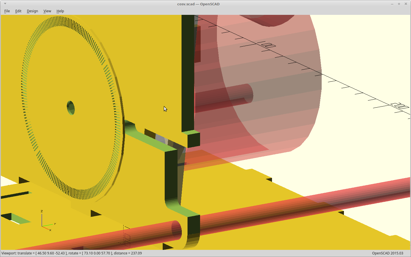
To keep in simple, our encoder disc is missing one pulse at our two home positions. We can find home by using missing pulse detection and a single photo interrupter. We had a hall sensor before, but it only told us when we were at 'home'. This is much more useful and uses the same number of pins.
The interrupter slots I picked here are cut at 4x the kerf width of our laser cutter.
That allows for 200 slots and still having more blocked space than cut.
Two hundred probably sounds really familiar, and it should. That is also the step count for the vast majority of NEMA 34/NEMA 23 stepper motors. I think you see where this is going....
As for the kerf to do this, don't get nervous here. Totally dialed in, the best our laser can do right now is 0.15mm. That's about 50% over spec. You'll be fine.
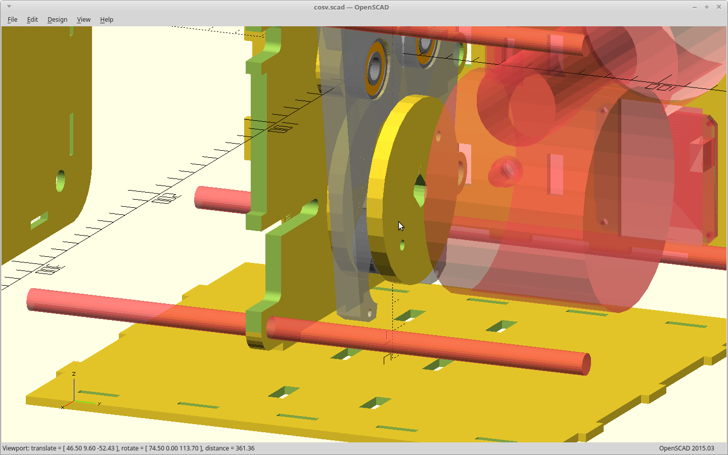
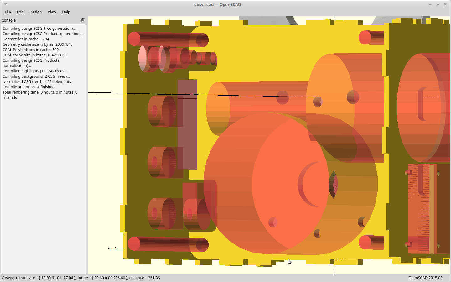
The complexity of all these new parts led me to model the outline of every single part. The clearance to some of them is really close, and I have been bitten here.
For example... the first version of this just eyeballing the motor position ended up with the threaded rod the stack was built from going ever so slightly through where the motor case was. Yep.
The files are cutting now.
Tomorrow is going to be very exciting.. :)
-
UI work.
04/24/2020 at 07:31 • 0 comments -
FFF files rendered
04/15/2020 at 18:49 • 0 commentsThe changes I made to the laser cut version have been applied to the FFF version. The arm bearing and lower mounts have been altered to use threaded rod.
The primary difference for FFF is that it uses single bearings whereas I have opted for two bearings stacked on the laser version. This lets me use the same model for both and just have the laser cut parts be thicker to get the added strength I need.
I also did not put the cutouts back into the FFF files. Printing them with low infill is probably stronger than adding the cutouts. They will definitely print slower this way though.
-
Laser cut revisions
04/07/2020 at 21:45 • 0 commentsNope. Didn't get these cut yet.
Yes, all the files have been reworked.
I gave myself a little more space between the cam bearings to allow for a larger (12mm) shaft. This larger shaft is a wiper motor. Worst case, I *know* I have at least one motor with the right torque and speed and I can move forward.
Eliminated all the sharp transitions of the arm model to avoid concentrating stress in the acrylic to a single point, and made it thicker. It is now built from intersecting cylinders instead of lines.
Smoothed out the base where it contacts the bag some more.
Changed the cam to use pins instead of bolts for the bearings. We'll see how this works. Saves me some height..
Changed the base bearings to use 8mm/5/16in bolts instead of 3mm and bushings.
Regenerated all the files. New rendered files are up.
-
Posting Parallel Project Progress
04/02/2020 at 23:19 • 0 commentsTested the #Human Lung Analog idea and it works. I can control the pressure and compliance now to better simulate our load.
#VISP - Ventilator Inline Sensor Package pcb's have passed review and the gerbers have been shipped up to @oshpark for three of the prototype boards.
Parts are here. We also dropped an Atmega 328 on the board and it actually routed.
Tried to get into the Dallas Makerspace to cut the new laser version, and they weren't having it. I can understand.
An alternate contact on LinkedIn may have been able to hook me up with a lab though. Sweet.
<EDIT> I decided not to take them up on the lab as that would actually put a member of my family here at risk. We are going to attempt to do the same thing, remote.</EDIT>
-
Laser cut thickness.
04/02/2020 at 13:40 • 0 commentsThe thickness for the bearings versus the parts when laser cut was a little bit of a problem. The bearings are 7mm and common material is 6.35mm or 3.175mm.
14mm is a nicer number, and also allows us to use washers on both sides of the arm bearings, which eliminates the stress on the bushings and the odd thickness requirement there.
So two arms cut from 6.35mm sandwiching a third cut from 3.175mm and we got a total thickness of 15.875mm.
Two regular washers positioned on either side of the bearings will make up that difference, and provide a larger clamping surface for bolting it together. The bushings then just keep the bearings centered and don't have to support the compressive load anymore. Also keeps things from flopping around.
Then for the cam we also use two stacked bearings. More area to wear on, and the bolt heads from the cam bolts no longer needs as much clearance as they will be at the same height as the now thicker cam surface.
I'll model it today and put up an image of this so you can see what I'm talking about, but I think this will be better. No new parts needed either, just duplicates of what we already have too, minus the paddle. It will need a wider hole.
COSV - Cam Open Source Ventilator
Roller cam based portable BVM ventilator.