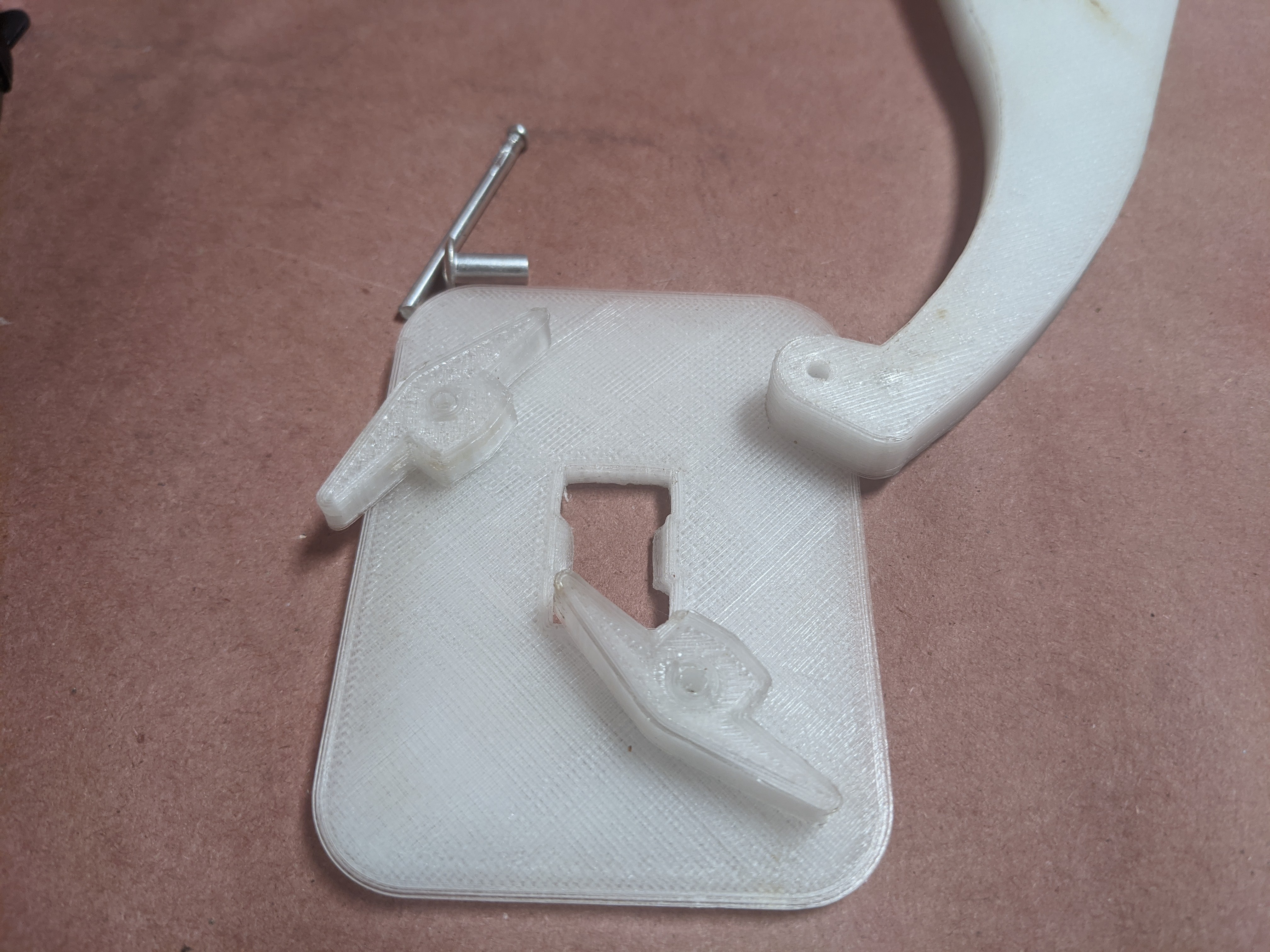
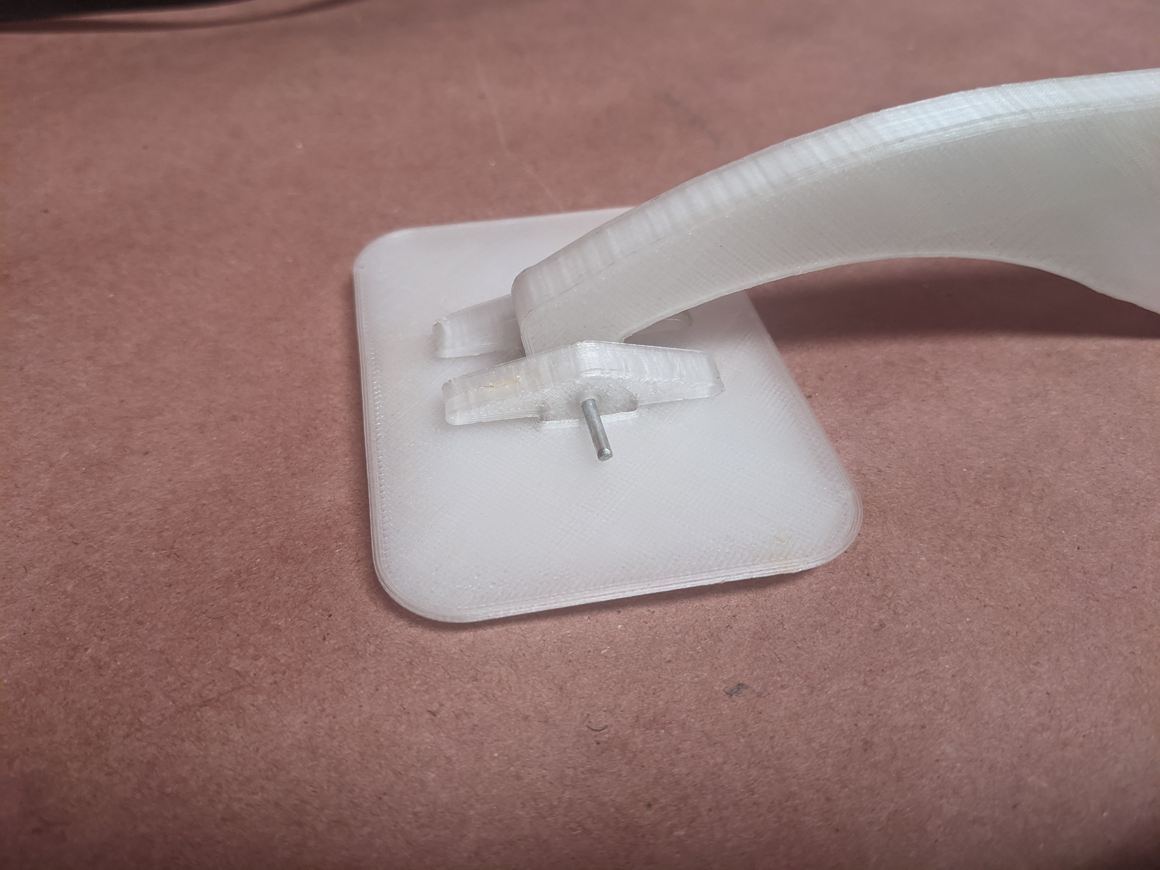
The arm prints and the corresponding paddles/pivots did not turn out perfectly, but they will still work regardless and I suppose that is part of the point.
I decided to use the post out of a rivet I had here as my retaining pin.
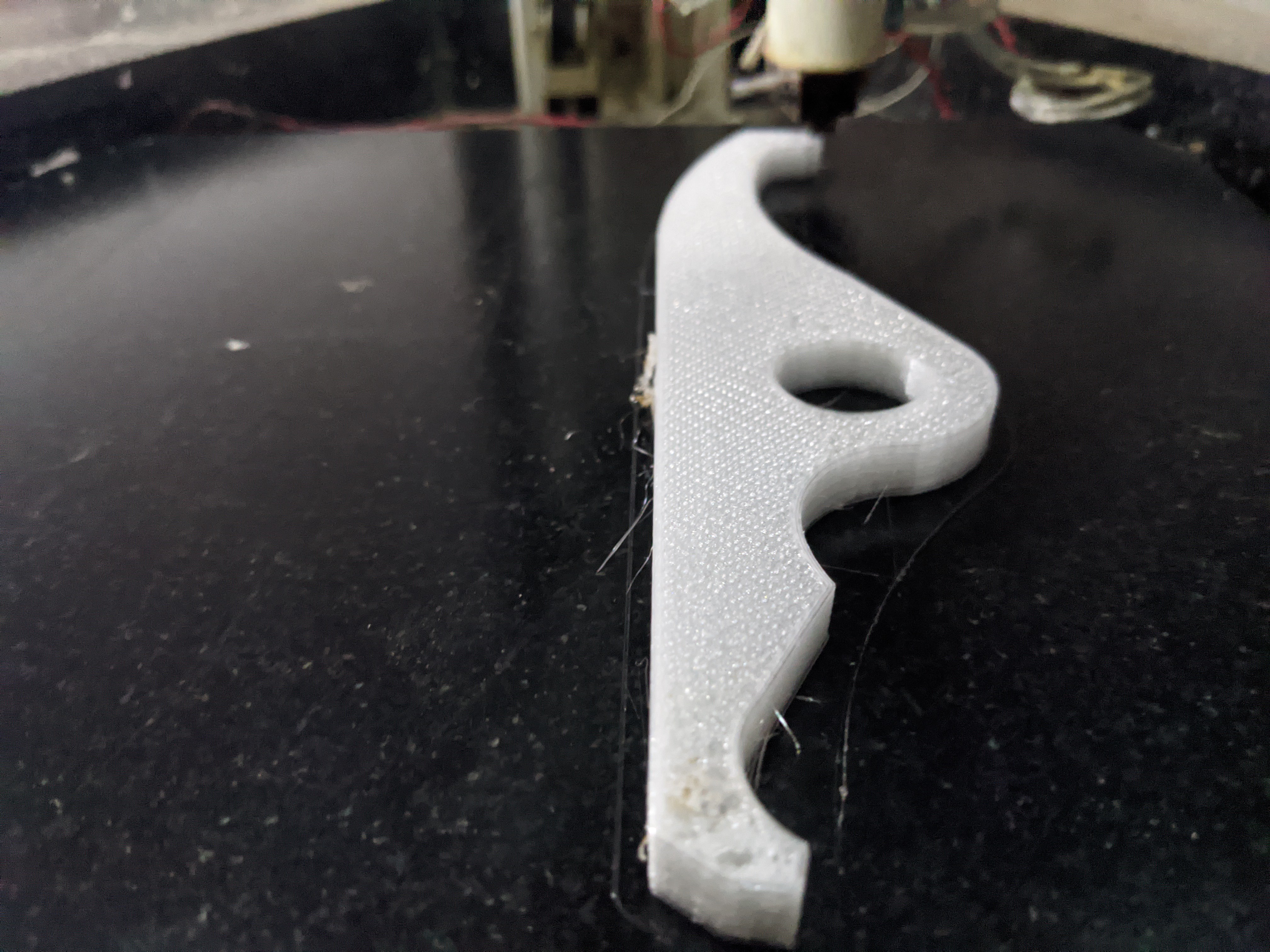
New arms, interchangeable with the laser cut version, printing in PETG.
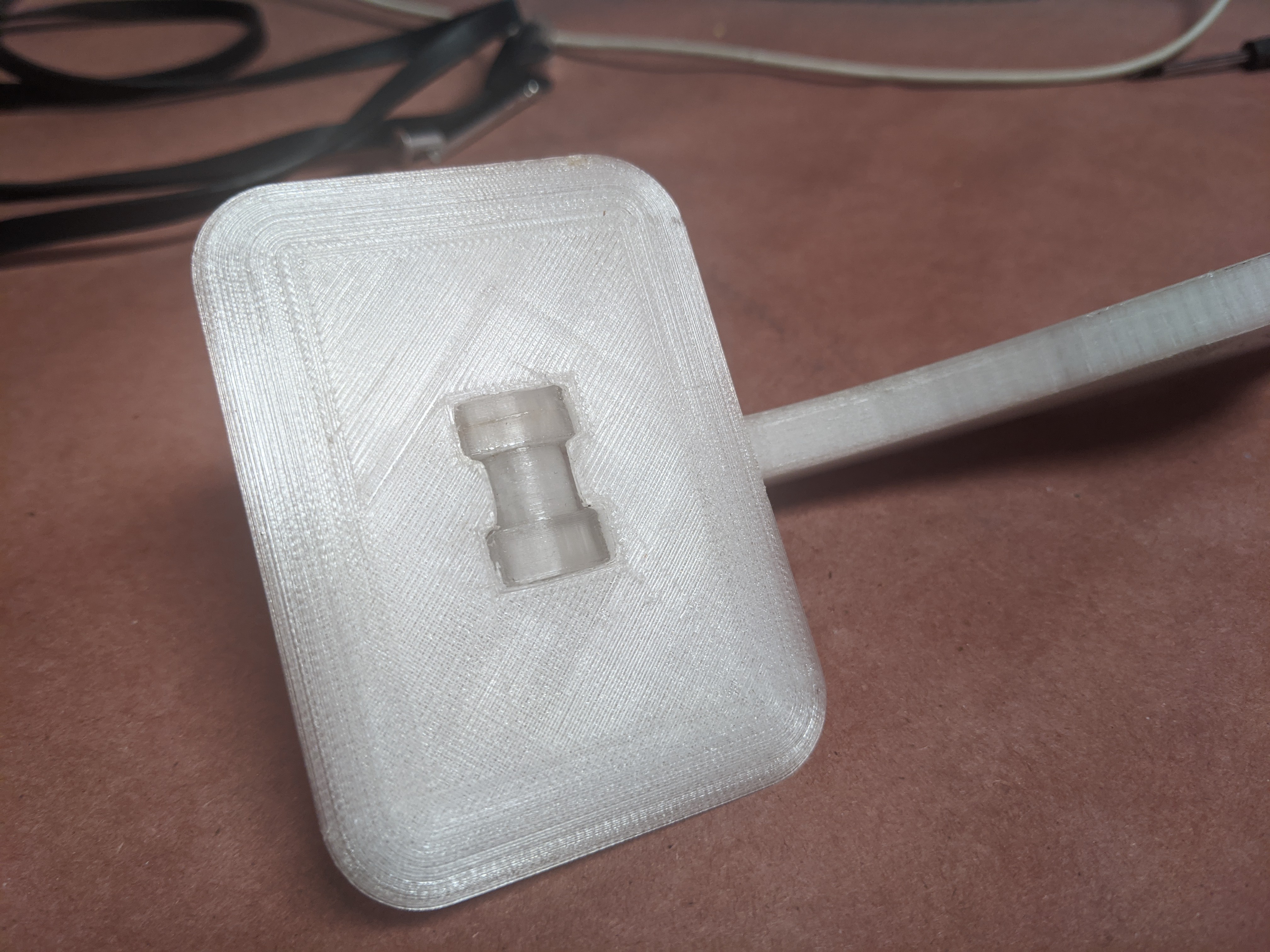
This version of the cam arm increases the compression stroke and allows for a parallel paddle position, but it does not compensate for the variable volume we have now during compression.
The variable rotation/delivered volume is complicating the PID loop we are using for our flow sensor feedback. We intend to compensate for the current non-linear flow with an inverted non-linear cam profile curve, but I haven't figured that out yet. This is not for lack of trying though..
For the last several weeks, we have been working with a team of 12 *very* talented people, with very specific and content relative wheelhouses, with the ultimate goal of submitting this as a project for the fifth round of the VA/NIH/Challenge America Covid response effort.
We had a product. It was flawed.
We gathered a *ton* of information from some highly qualified end users of this device, and then solved every problem that was solvable. Sorry CPAP.
As of a couple hours ago, this project just won the VA/NIH/Challenge America challenge, round 5, and so is a product that is moving forward. Yay.
I will document the full extent of what this entailed eventually. (famous last words for me)
Congratulations and great thanks to the team of people who helped to make this happen.
#DP Ventilator just made it to the finals of Hackaday prize without solving *any* of the core requirements of this type of ventilator beyond squeezing the bag.
Uses one sensor.. so they can't detect if the hose is kinked, if a nurse turned on a peep valve, or if the patient is even still connected. This *will* do the wrong thing in every one of those situations and harm the patient.
It is also impossible to implement any proper ventilation modes like that. If you implement pressure-based control you need to have flow as an output. If you implement flow-based control you need to have pressure as an output. Otherwise you simply can't do the right thing, again harming the patient.
Uses a long hose between the ventilator and the patient guaranteed to build up CO2. The valve and sensor stack needs to be connected at the patient or you never empty that hose. The patient ends up breathing in 20% of the air they just breathed out over and over. You think wearing a mask is bad...
Uses the sensing idea of barometric pressure sensors, poorly, we submitted back in February to HelpfulEngineering during the initial massive sensor shortage, with no credit. It is possible they ended up here though without ever seeing that. Probably likely actually given they missed so much of the mark.
Is mechanically complicated and is much more likely to bind and fail with sliding elements. We designed ours per the UK ventilator specification of surviving for a half a million cycles over two weeks.
Is unable to actually meet the UK ventilator specification of an inhale cycle time of 0.3 seconds at 15cm/H2O. We started completely over so we could.
I sent this as a message to the project chat channel a few days ago with an '@mention' for everyone who is currently listed as a project member, but I'm really not sure that worked as intended, so I am posting this here as a project log as well.
The message, with some added information for the general public...
I originally didn't submit this project for any contests as I didn't want to have that dictate the direction of the project. I have fallen victim to this myself in the past.
I also didn't plan on this project getting drawn out as long as it did, but getting Covid myself and other IRL events have changed the timeline here.
@Steven.Carr @Kevin Patel and I have finally been able to get back to putting this on the front burner again in the last week or two.
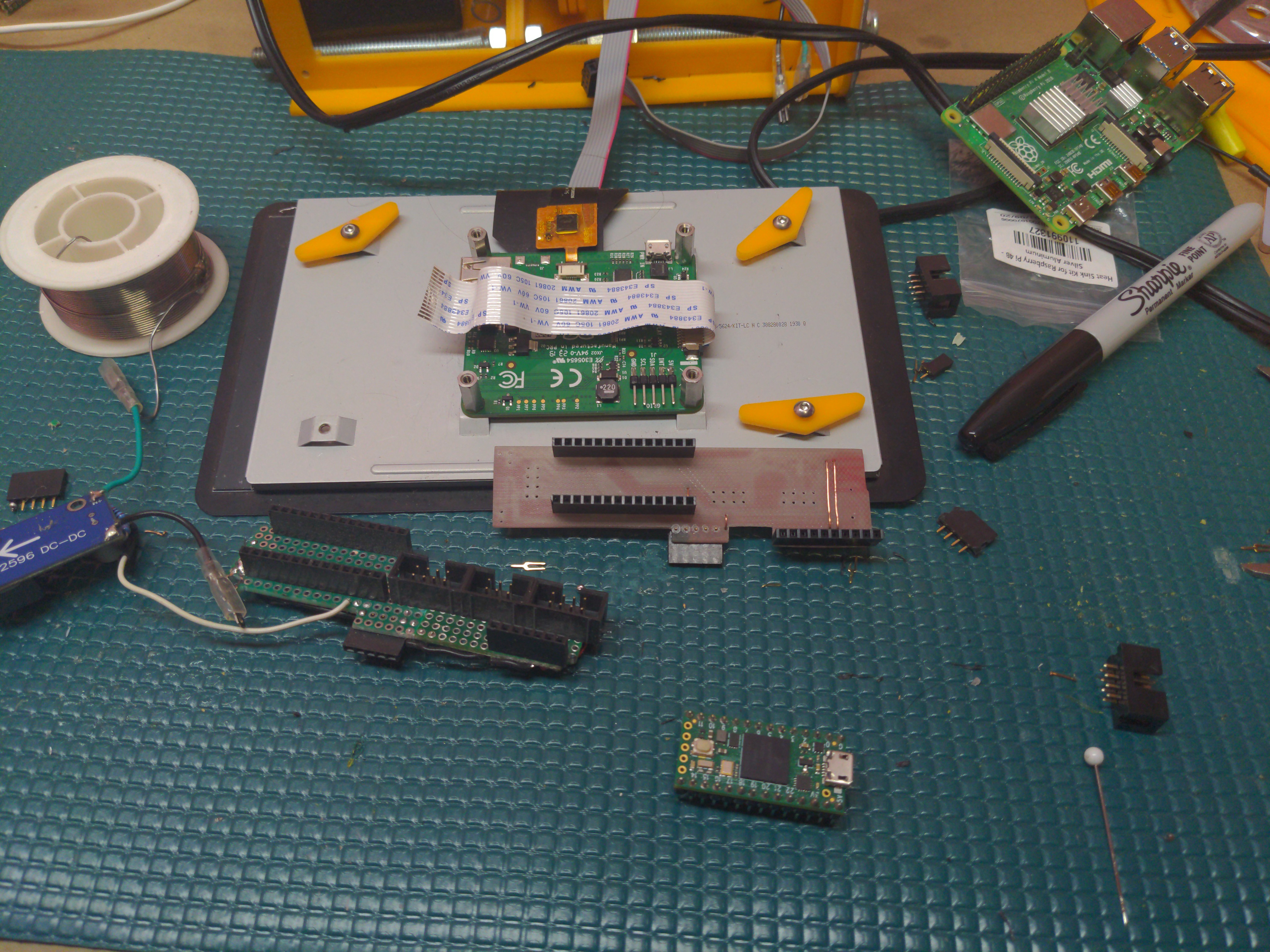
There is a new carrier board arriving from @oshpark tomorrow generated by @Steven.Carr which supports both the inexpensive analog input/SPI display interface and the full blown and intentionally isolated Pi display version of the UI. This methodology was employed so that we can move forward with a potentially far more useful UI without requiring exhaustive run level testing.
There is also another run of the VISP project on the way with support for 4 wire multiplexed I2C and two sensors per port, and both Steven and I have the latest laser cut versions ready for assembly.
When I started this project I also kept it close at first, but then later on I allowed anyone who wanted to join the project, to join. This has resulted in a bloated roster where the majority of people here who are members of this project have not actually done anything with regards to the project. This is partially my fault for being a bad organizer and I accept that.
However, If I *do* submit this for the HAD prize at this point, everyone who is a member will need to opt-in and accept the prize rules. With the current roster, I am not sure that would *ever* happen.
So, I'm going to drop a notification here (in the team chat) for everyone to sort this out. Please respond to it if you wish to remain a part of the project and have the time/resources to actively contribute. Deadline for submission is Monday morning. I will be trimming the roster just prior to that.
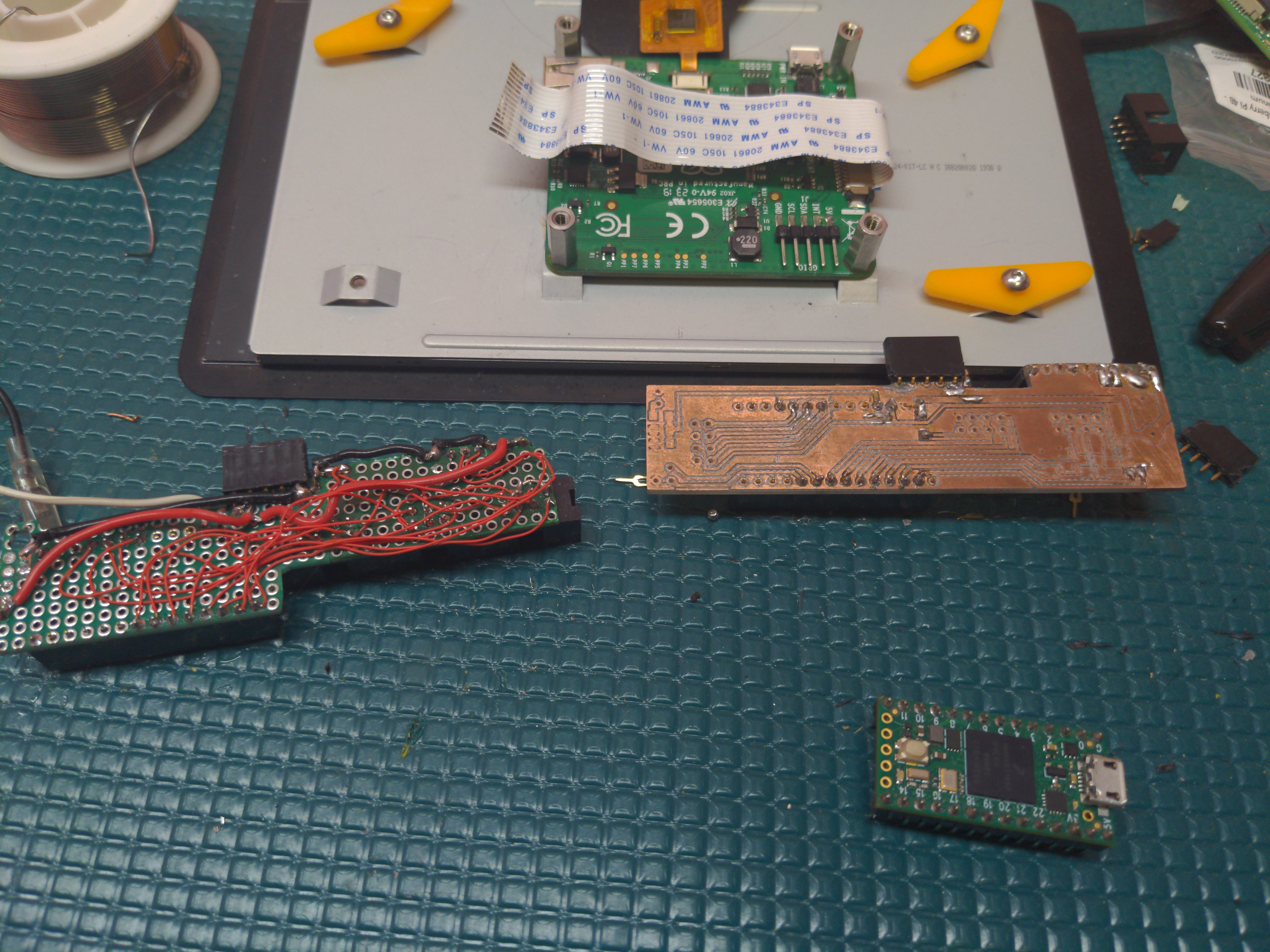
@Steven.Carr has been happily milling out PC boards and laser cut experiments on his very nice equipment. I was growing envious as I sit here airwiring stuff.
Four years later, I finally got around to building the PCB milling attachment for #Arcus-3D-M2 - Mixed material filament printer . I always had a couple extra AL end effectors and 12 extra mag balls for exactly this purpose. Necessity is your mother.
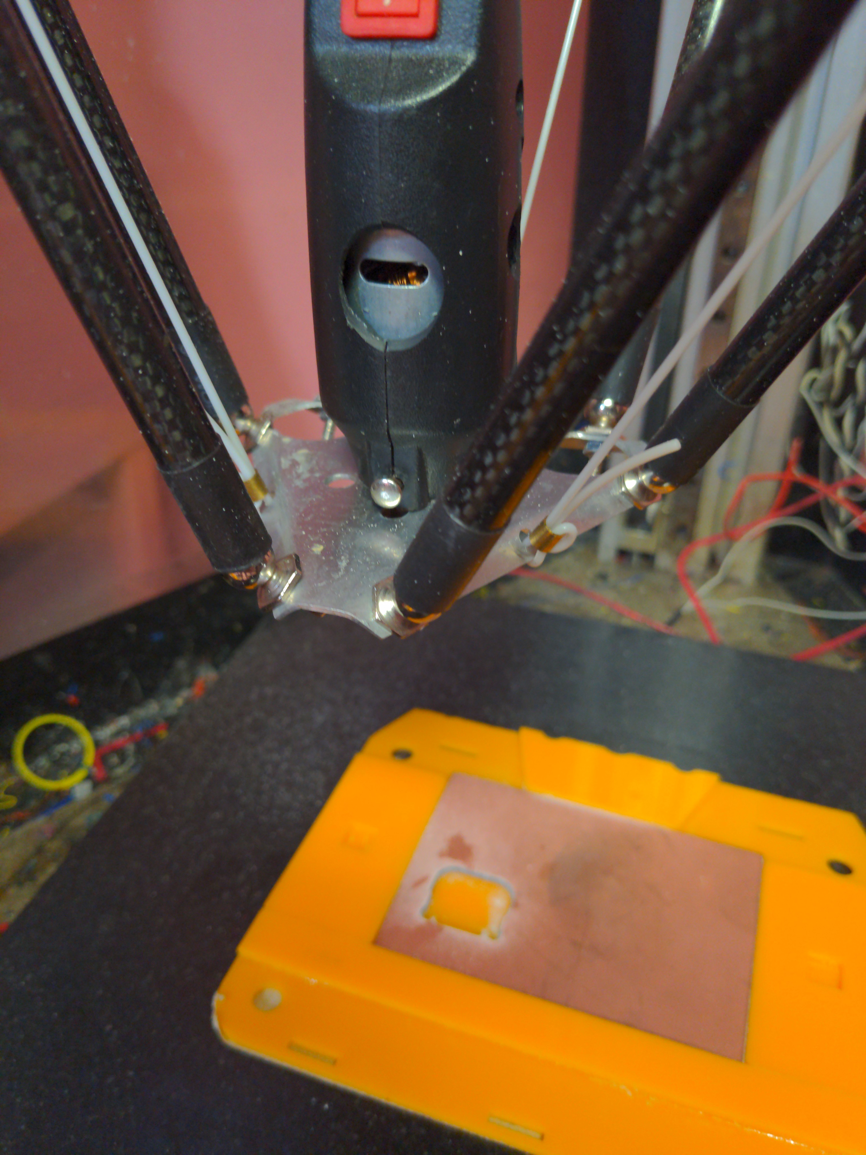
Took the HF Moto tool I had and machined a full depth collet for it to specifically fit the PCB milling bits I have been carrying around in my toolbox for the last 4 years. The normal collets for this tool when presented with any side loading wear out in about 5 minutes as they are relatively soft brass, and only hold the first 3mm of the bit.
I also drilled massive holes in the housing to try to cool the motor a little better so it doesn't melt its mounts when running continuously.
This little motor does actually have *one* nice bearing in it, and carbon block brushes. It may actually do okay for a while now.
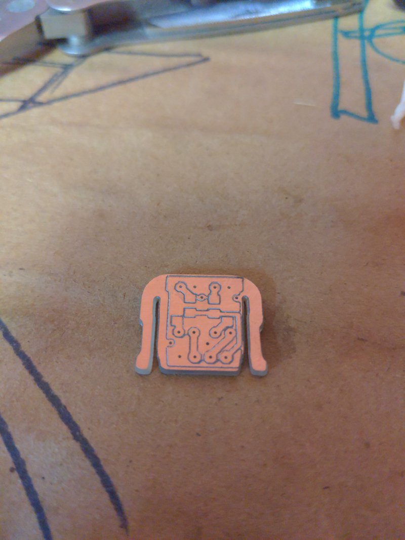
Anyway... The results.
This part is the PCB that holds the two optical encoders we are using which allow us to turn DC motors (a Ford F150 wiper motor) into proper servos for about $4 in parts.
I don't know if it is intended to be offset like that or not. I assume so because I actually ran it twice as I got the depth wrong the first time.
I just took the gcode that @Steven.Carr ran on his Tormach (envy) and stripped out all those unnecessary things like tool changer commands and actual spindle speed speed control, and reduced the depth of the drill cycle to just give me the centers by relocating Z=0 with a G92 before it.
Then again using a Tormach to mill PCB's is akin to using a pulse jet engine to spray sanitizer. Yes, I am referencing you ACME Creation Labs.
And.. a video.
I was pretty conservative with my feedrates as I had no idea how this would do.
Steven ran this at F3.0. I turned that down to F1.0, but ended up running the trace etching at F3.0 via feed rate override, but then dropping it to F0.6 for the final pass cutting full depth on the cutout.
I also discovered my 3D printer UI does not properly handle running in G20. Imperial coordinate systems FTW. I am choosing not to fix that.
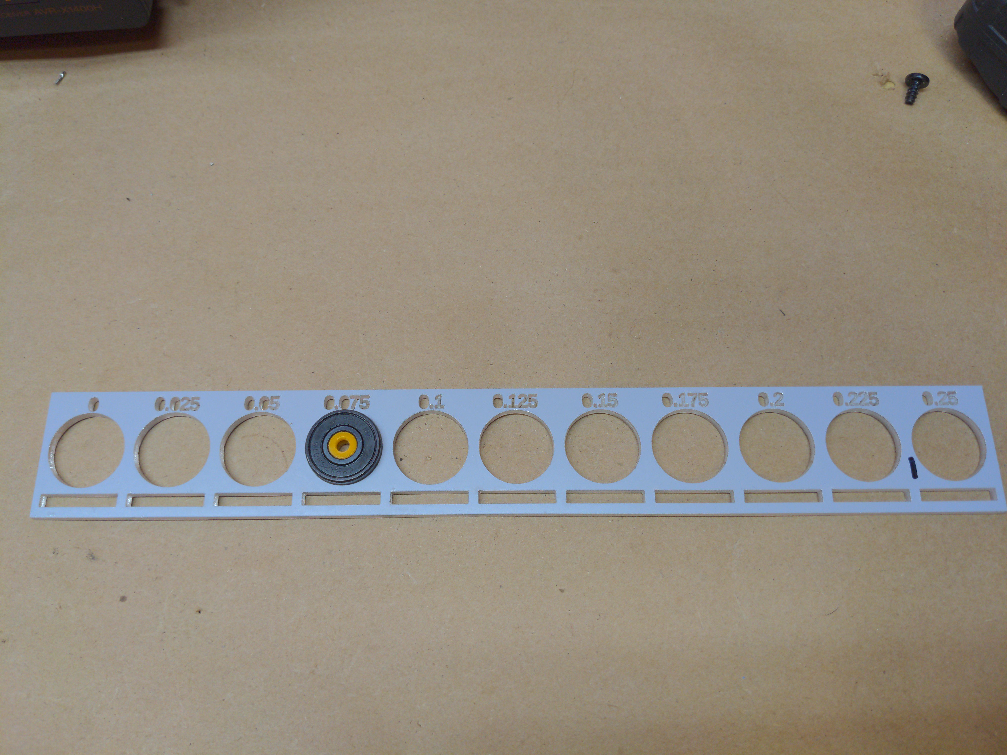
Made a test jig for determining the proper setting for laser kerf.
You stick a bearing in the holes until it fits, and the number above that hole is your laser kerf. Similarly the slots below are for testing the edge joint kerf.
This is not a judgement on anyone involved in said 'Drama'. Mistakes were made, but I don't believe anyone actually intended for the 'Drama' happening right now, to happen.
I chose not to believe that.
In any case, I basically burned myself out and was physically ill for a while, and so I personally have done very little in the way of actual work on this project. Sleeping was far more attractive and probably much better for me.
In the meantime the laser cutter I was using to prototype my parts here 'went away', the city is on lockdown, the AC is not working, and I then I enticed a few very time consuminmg things to bite me. It has not been a good week.
We will prevail.
I do have *one* working prototype though and through the significant effort of @Steven.Carr probably multiple modes, servo control of the motor subsystem, failure detection of individual components, etc. Working is a relative term here as I still have yet to fix what may just be a simple serial issue to even find out. Basically he wrote a pure C version of what I did in Python/Kivy for the UI and the serial protocol to implement it, in what seemed like a day. Bastard. :)
At this point though I can probably get to that... um... Sunday.
 MasterOfNull