Okay here's the specs:
- Dimensions: same as the original, measured from photos.
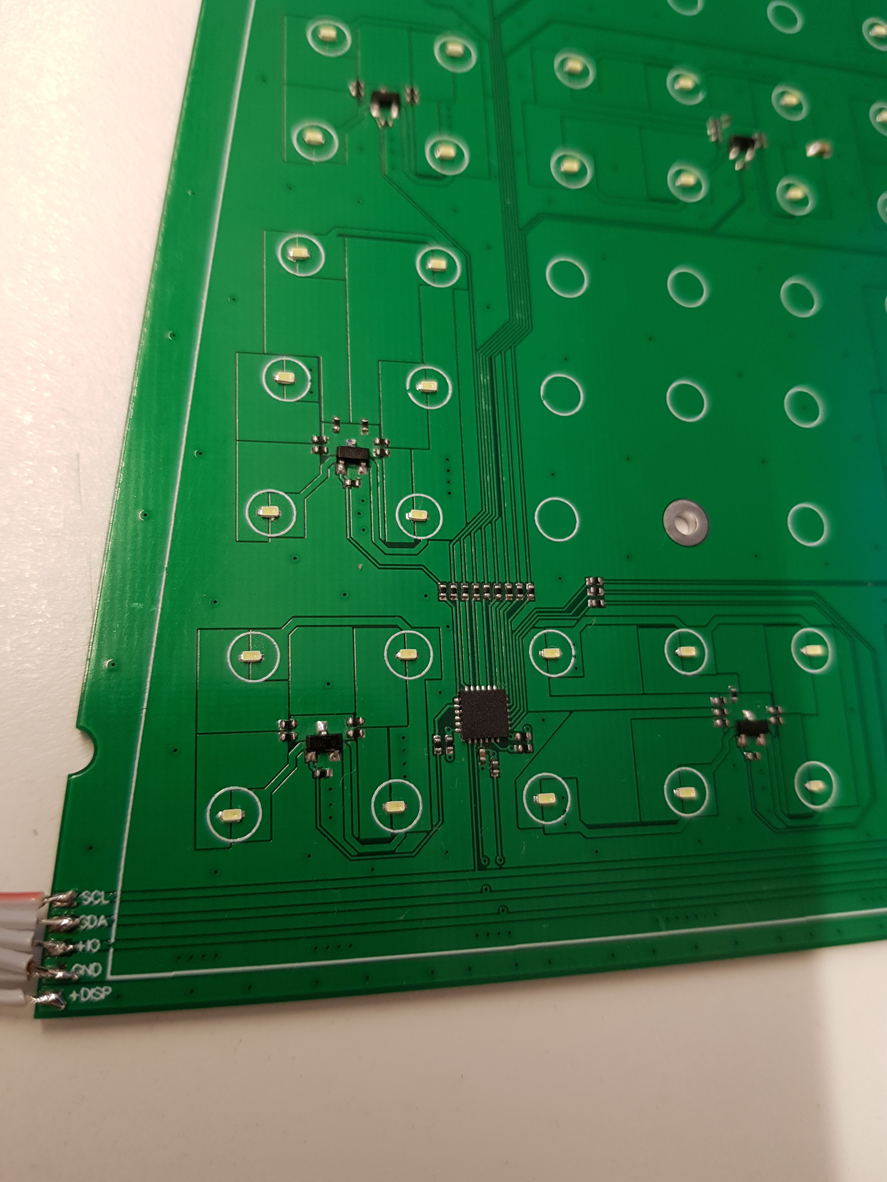
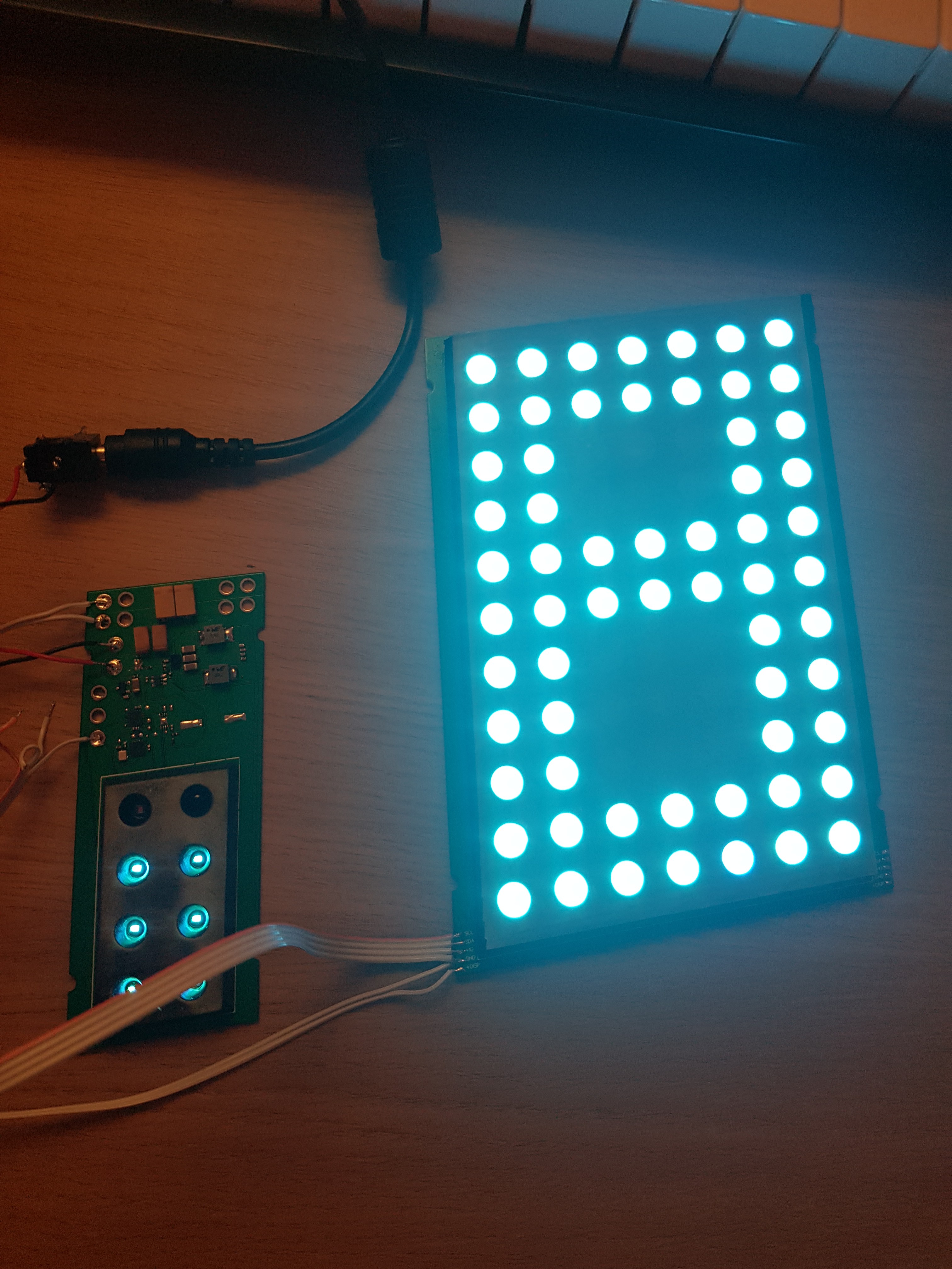
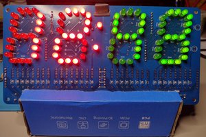
- Display: LEDs for every dot (found one one that light up in the exact same color as the phosphors in the original VFDs). That's 266 LEDs. LEDs shall be housed in a plastic matrix frame with holes filled with frosted semi-transparent resin (just like how seven segment LED displays are constructed).
- Power required:
One LED draws 2.9V*0.01A=0.029W
All LEDs shall therefore draw 0.029W*266=15.25W
- Power supply: 9V/12V adapter (because I have plenty of those from previous projects).
- Interface: IR remote control (because the clock will be hanging on the wall somewhere beyond physical reach)
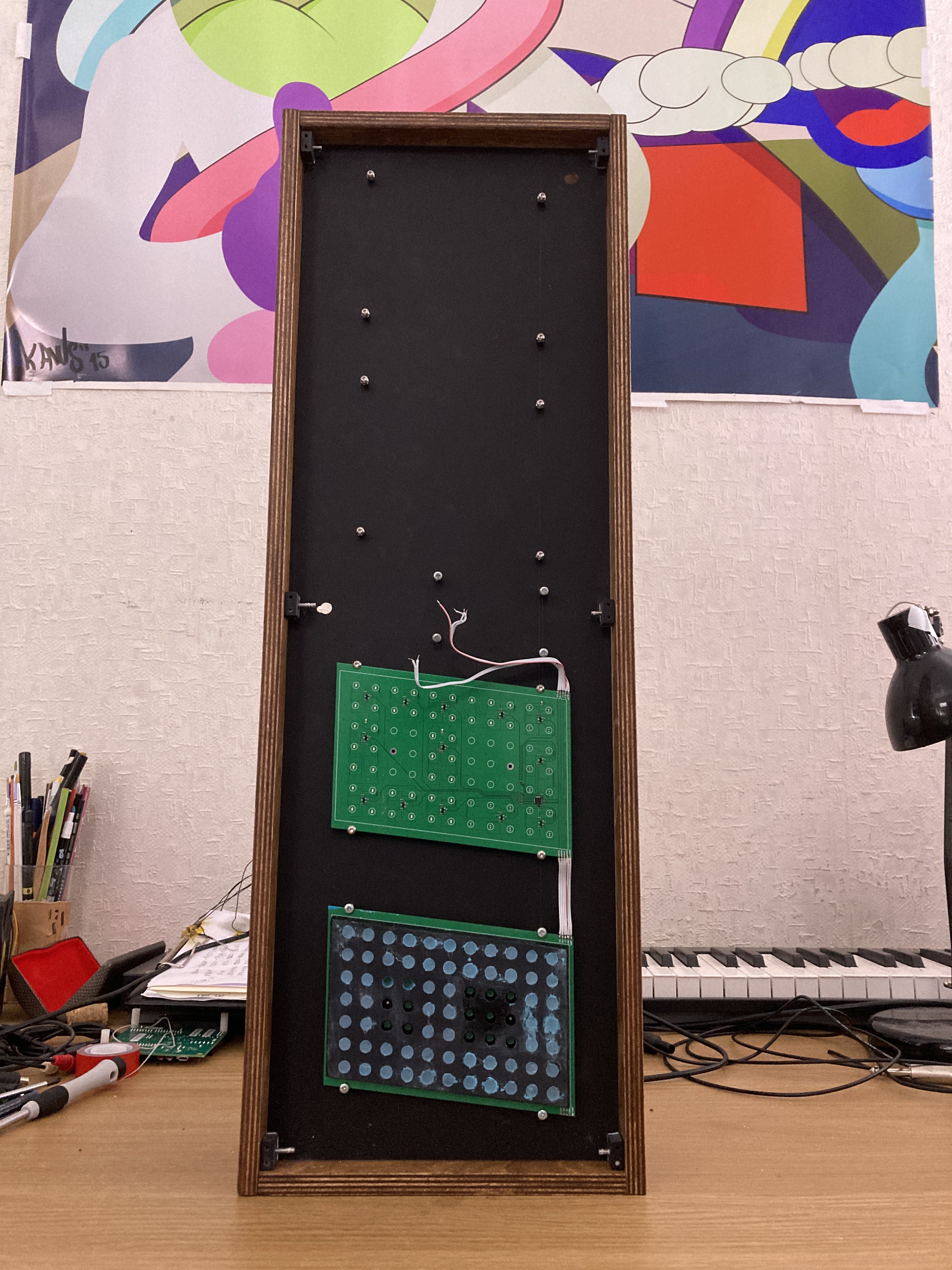
- Construction: Front panel - dark green transparent plexiglass 660mm x 210mm x 3mm. Main frame holding the PCBs - matte black plexiglass 660mm x 210mm x 3mm. The rest is 16mm thick wooden frame around the plexiglass. Holding everything will be a combination of 3D printed spacers and screws. No buttons (unlike the original, very modern though).
- IR Remote: The remote shall have 5 buttons: timer, plus, minus, set, date/time.
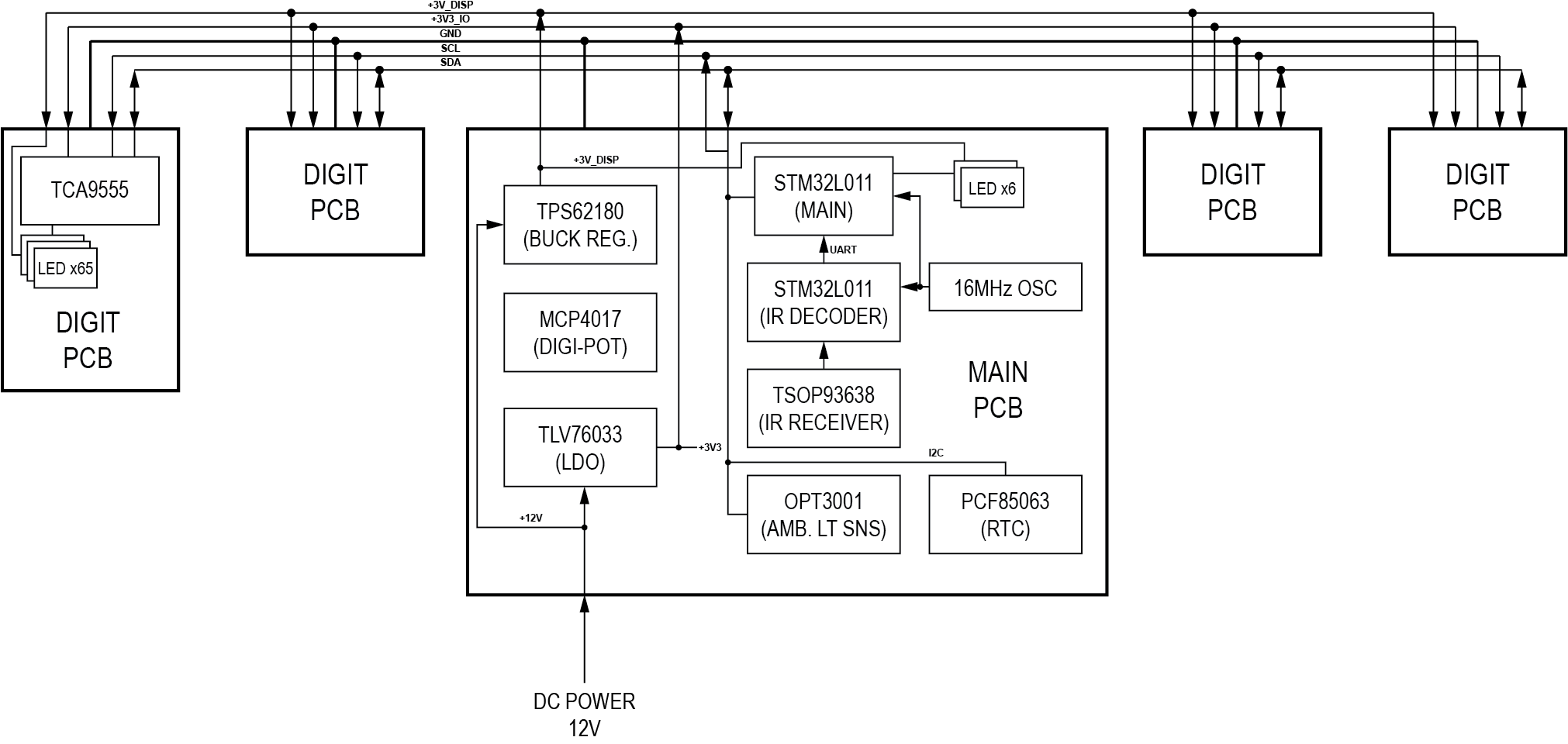
- Timekeeping: Real Time Clock chip with crystal source and a backup super-capacitor.
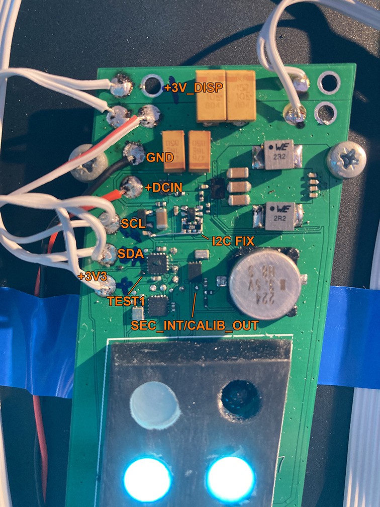
- LED driver: no driver, just MOSFETs and an adjustible voltage Buck regulator (for dimming).
- Brains of the device: STM32L0 series MCU and a bunch of GPIO expanders to control a bunch of LEDs. Maybe a seprate MCU to decode IR signal from the remote. Might be cheaper that using larger STM32 MCU with lots of timers. (I use like 2 timers for decoding IR).
 makufelis-xyz
 Marius Taciuc
 matt thurstan
 Ken Yap
 Ray John Alovera