makufelis-xyz
-
Final assembly & calibration
08/22/2020 at 11:13 • 0 commentsWith not much left to do here I assembled the final LED boards. After hooking them up I noticed that some of the LEDs had a slight tint towards blue which I'm pretty sure is a consequence of overheating while soldering so definitely something to take into consideration for later assemblies.
Another thing I did was to calibrate the RTC clock so it runs in tune with the atomic clock. Since this clock doesn't have WiFi or GPS syncing ability the calibration is a must IMO.
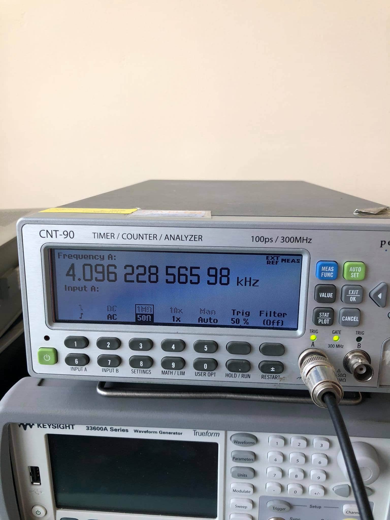
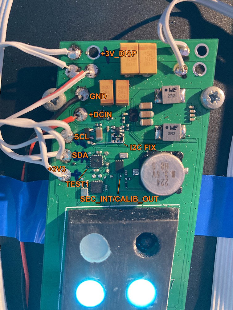
So to calibrate the RTC i connected a frequency counter to SEC_INT/CALIB_OUT and held TEST1 low. That way the clock entered calibration mode where the RTC chip outputs its current running clock of 4096Hz at SEC_INT/CALIB_OUT and I could compare it to reference clock of 4096Hz and then calculate the deviation in ppm.
![]()
So the clock was speeding at +55.8ppm which might in part be a result of me not putting any crystal capacitors which makes the crystal frequency go up but it's fine.
Oh, and I made the typical rookie mistake of not putting in I2C pull-up resistors in the schematic so I had to fix that.
![]()
-
Enclosure bussiness
07/20/2020 at 19:24 • 0 commentsHello again!
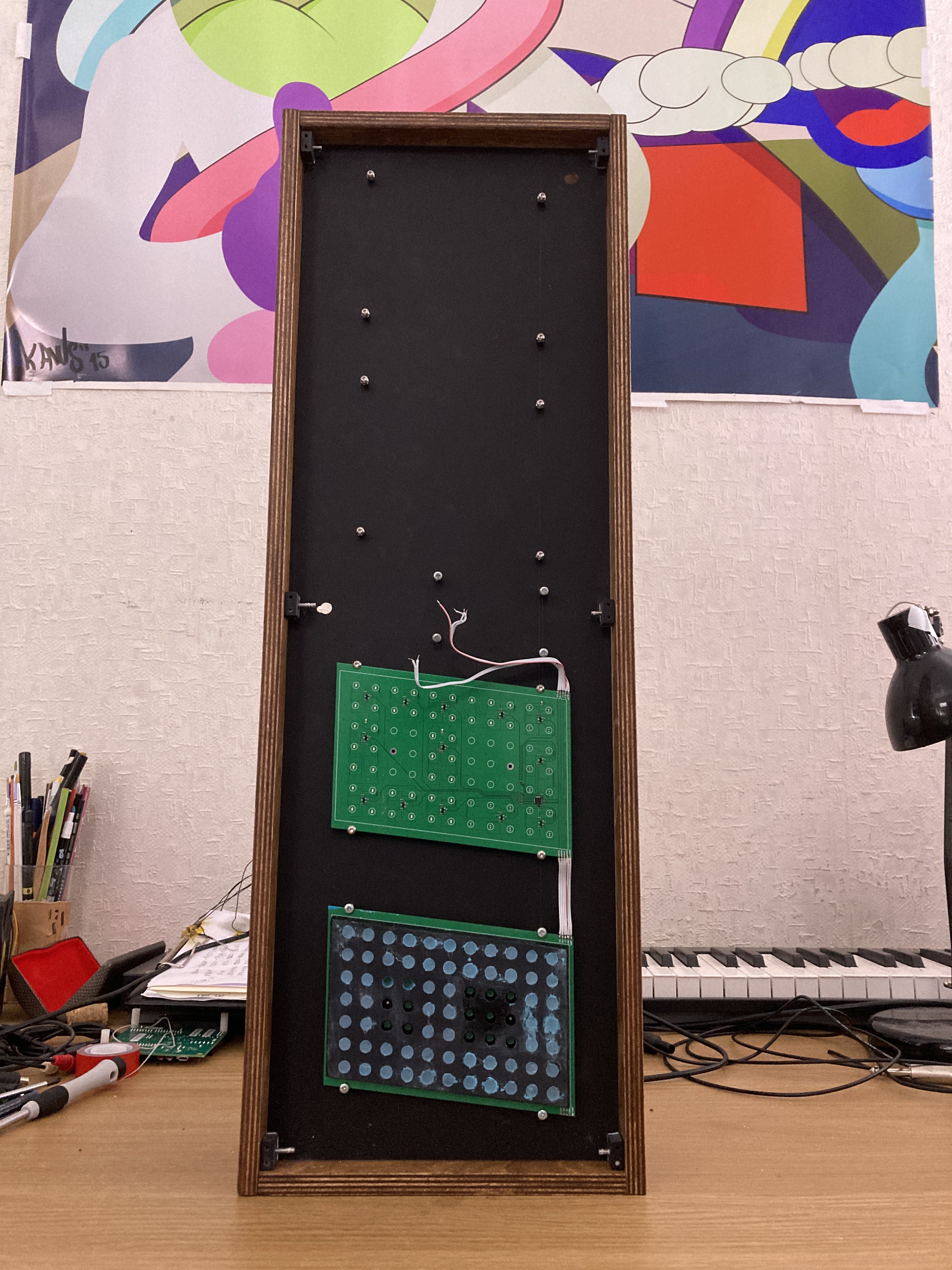
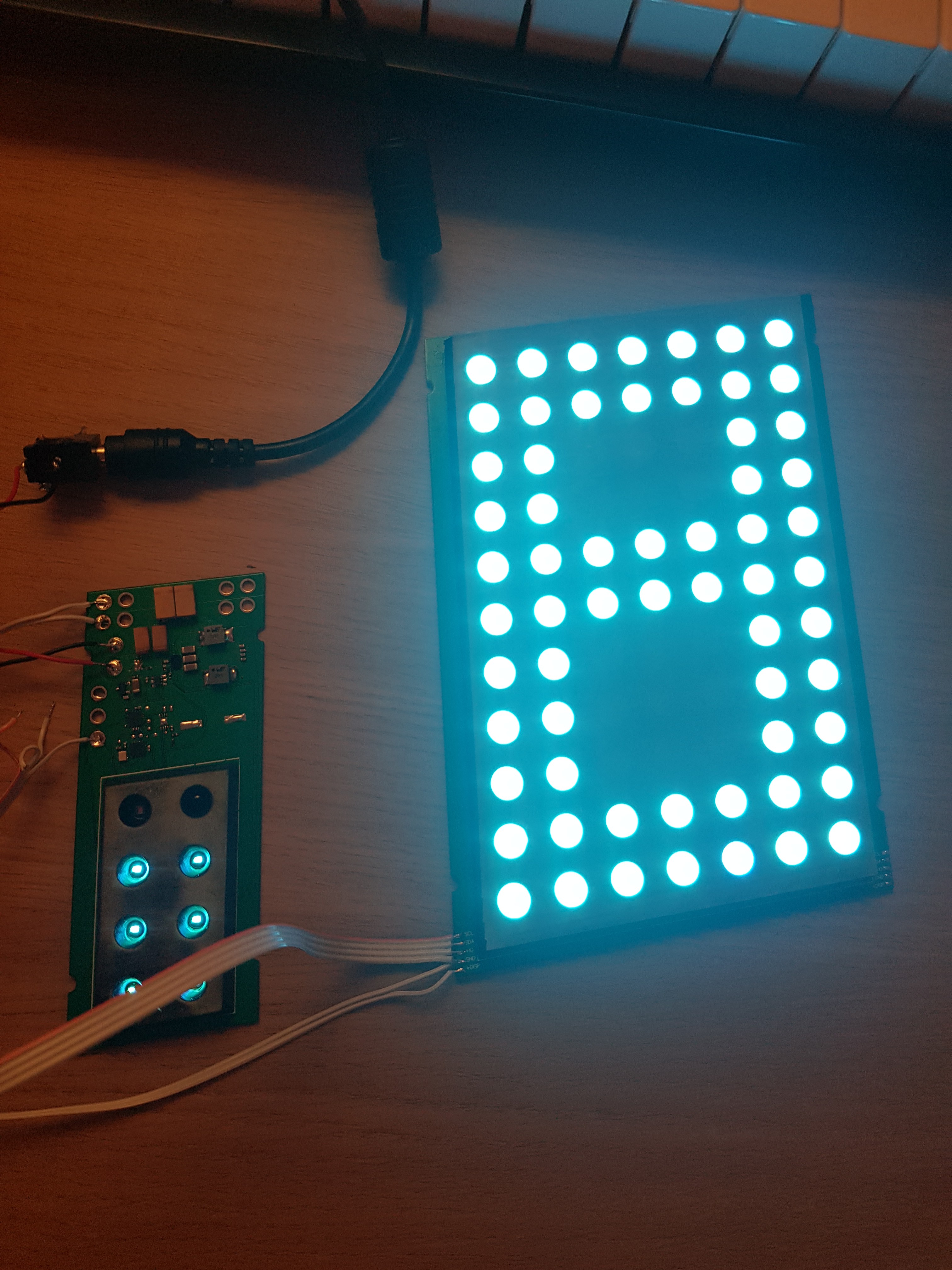
The LED assembly that I made looked too bright so I've been trying to find ways of diffusing the individual pixel LED and came up with a cheap and repeatable way of doing it which is filling the pixels with translucent hot glue and it worked wonders!
Currently I only have one and a half LED assemblies made - looking forward to receiving the rest 130 LEDs to complete the clock.
Meanwhile my neighbour cut out the wooden panels for the enclosure and they look amazing. My neighbour put an extra step and painted them with this very nice varnish, makes em look more authentic.
![]()
-
Success with PCBs
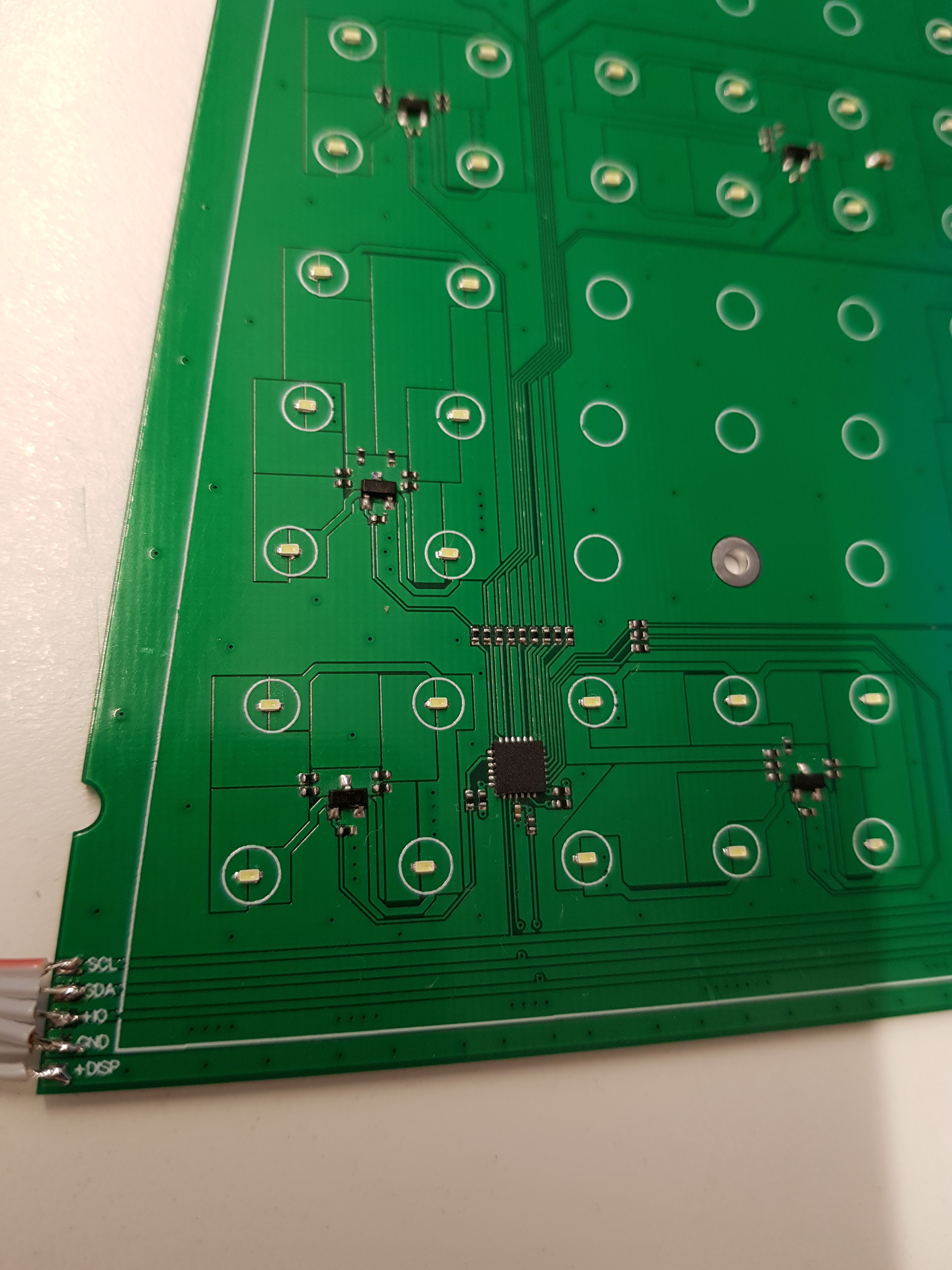
05/29/2020 at 13:45 • 0 commentsGot my PCBs from china, assembled them and got it working the first time wich is kinda suspect but I'll take it!
Started with testing the digit boards, the variable power supply then the ambient light sensors, oh and the infrared receiver..
Next step is to test the RTC clock and backup supercap circuit to see if it will last atleast a day on backup power..
![]()
![]()
-
Schematics..
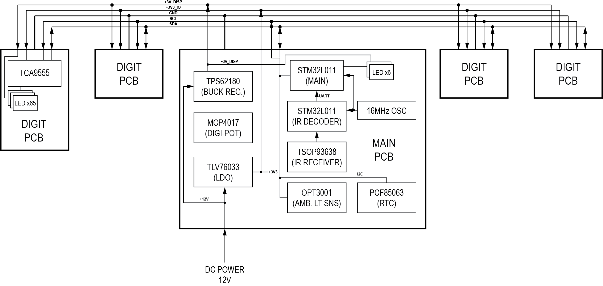
04/06/2020 at 18:03 • 0 commentsAlright, the schematics and PCB are done and I drew in parts that I already have hoarded over the years so there's gonna be a mix of parts with packages ranging from SOT-23 all the way to BGA which I'll be assembling by hand so we'll how this will pan out.
The buck regulator for LEDs will be a particularly tricky one both in terms of assembly and making it work since its this wacky dual phase topology which is new for me so looking forward to exploring new avenues of power design..
Oh and controlling the voltage of the regulator using a digi-pot also is an intriguing topic in itself..
So yes, the LEDs will basically be connected in parallel from the high-current 2.5V-3V adjustible voltage bus. That should make the LED segment driving way easier.. or..will bring some issues with unintentional LED dimming during heavy current load..
![]()
Elektronika 7-06 clock replica
A very-modern take on the popular late-80s soviet clock.