Close
0%
0%

The Guitar Pedal Project: Multi-Effect Processor

A guitar multi-effect stompbox that allows musicians to create new and never-before-seen effect creations using their mobile phone.

Similar projects worth following
Welcome to a page dedicated to our Senior Design Project at the Milwaukee School of Engineering. This is a Raspberry Pi based guitar multi-effect processor, using the PureData DSP engine and a convenient mobile app for effect editing and creation. The project was conceived in Spring 2019, and over the course of the 2019/2020 academic year our team of five members has been working to bring it to fruition. Our team includes three ElectricalE students, one ComputerE student, and one SoftwareE student.

Our progress was slowed in Spring of 2020 by the international coronavirus pandemic, but we are working remotely to complete the project to the extent we can. Keep in mind that this is a work in progress, and ultimately not a polished product. Expect information on this site to guide you towards duplicating our work, with insights, explanations, schematics, and code.

A special 'thank you' to our project advisor Dr. Kelnhofer, who helped us bring our project to life.

Project Overview

This project is comprised of five main subsystems, tied together by the main processor board, the Raspberry Pi 3B+.

The subsystems are as follows:

  • The Audio Codec
    • Provides Hi-Fi audio input and output for the Raspberry Pi
    • Communicates over i2C and I2S/SPI
  • The Preamplifier
    • Impedance matches between guitar and Audio Codec
    • Comprises of an operational amplifier (OPAMP) circuit in voltage follower configuration
  • The Power Supply
    • Takes a DC 12v input
    • Provides +5v and +3.3v outputs at 3A of current each
    • Powers all other subsystems
  • The Human Interface
    • Allows modification of effect parameters (such as boost, modulation amount, etc)
    • Comprised of two ADS 1015 ADC boards, four potentiometers, and an expression pedal input
    • Python script is required to take the ADC values and use them in the DSP
  • The Mobile App
    • GitHub page is here: https://github.com/kremerbe/GuitarPedalApp
    • Provides the mobile interface for the hardware
    • Written in React Native with support for Android and possibly Apple in the future
    • Allows importing PureData effects you or someone else has created
    • Keeps a list of effects you like on your phone for easy-access
    • Allows effects saved in the app to be sent to the hardware utilizing Bluetooth

Design Project Poster

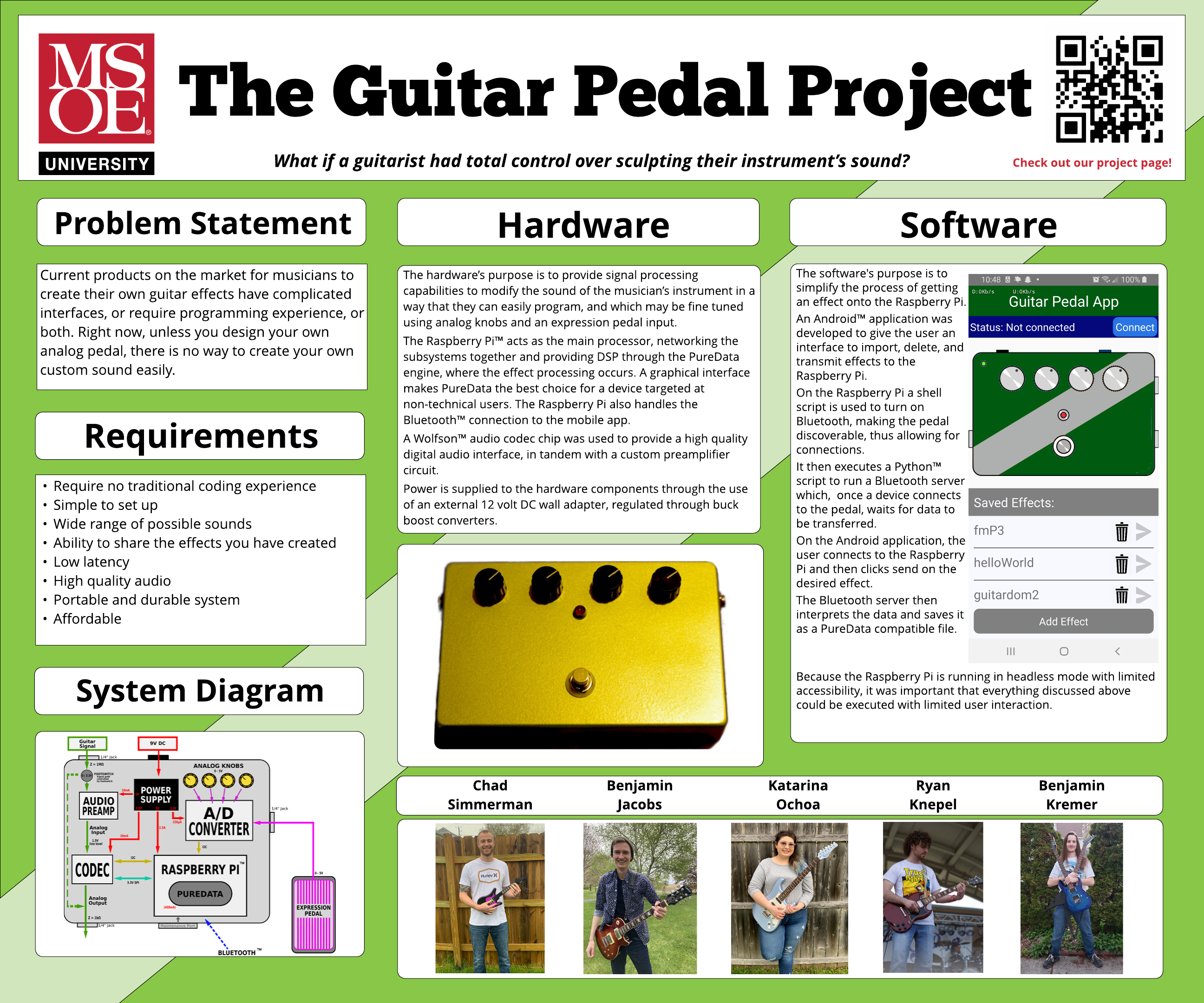
As part of Senior Design in the MSOE Colleges of Engineering, each team must make a large-format poster summarizing their work and accomplishments over the past year. Below is our poster, created by team member Katarina Ochoa.
BlueoothServerPiFiles.zip

The altered rfcomm-server.py that should be placed in the pybluez/example/simple/ directory. As well as the shell script to turn on Bluetooth and run that server script.

x-zip-compressed - 1.96 kB - 05/20/2020 at 14:58

Download

Hardware PCB Schematic diagram.pdf

A detailed prototype PCB schematic for the hardware integration. From Ben Jacobs' engineering notebook.

Adobe Portable Document Format - 1.05 MB - 05/14/2020 at 19:54

Preview

Audio Subsystem Files 5-12-20.zip

Files pertaining to the Audio Codec Subsystem, including the PureData config file, run_pd.sh, a sample effect, and the two versions of the knobs object.

x-zip-compressed - 2.86 kB - 05/12/2020 at 16:49

Download

Human Interface Files 5-12-20.zip

Files pertaining to the Human Interface Subsystem, including the knobs Python script and schematics and block diagrams.

x-zip-compressed - 105.90 kB - 05/12/2020 at 16:40

Download

config.txt

Boot configuration for the Raspberry Pi. Pertinent to subsystems which use i2c, SPI, and Audio.

plain - 1.62 kB - 04/29/2020 at 22:23

Download

  • 1 × Raspberry Pi 3B+ Main processor in the stompbox. Running PatchboxOS for realtime audio.
  • 1 × Wolfson WM8731 Audio Proto-board Utilizes the WM8731 audio codec chip for enabling audio input and output on the Raspberry Pi. Operate over i2c and SPI.
  • 1 × 3PDT Stomp Switch Three pole double throw stomp switch for true-bypass circuit
  • 2 × Adafruit ADS1015 Analog to Digital Converter breakout boards Two four channel ADC boards are used to take analog input from the effect parameter knobs. Operate over i2c.
  • 1 × Hammond 1590DD Aluminum Enclosure Durable housing for all hardware components.

View all 11 components

  • Setting Up For App to Raspberry Pi File Transfer

    cesimmerman05/18/2020 at 20:52 0 comments

    Follow these instructions to set up the raspberry pi to be able to receive files from the app. Almost the entire list of instructions below is thanks to a tutorial on YouTube referenced at https://www.youtube.com/watch?v=DmtJBc229Rg 

    One major issue came from the git repository link, which I have fixed below.

    • Install Necessary Software on the PI: 
    sudo apt-get install python-dev libbluetooth-dev
    
    •  Edit Bluetooth service to flag
    sudo nano /lib/system/system/bluetooth.service
    • About the 7th line down is:
    ExecStar=/usr/lib/bluetooth/blluetoothd 
    • add a -C to the end of that line to look like
    ExecStart=/usr/lib/bluetooth/blluetoothd -C
    • Save, exit and reboot. 
    • Run the script to turn Bluetooth on from the command line
    bash home/patch/bin/bluetoothOn.sh
    •  get pip
    cd /home/patch/
    wget https://bootstrap.pypa.io/get-pip.py
    sudo python get-pip.py
    git clone https://github.com/karulis/pytbluez
    cd pybluez/
    sudo python setup.py install
    •  Create Script to enable Bluetooth serial Port
    cd /home/patch
    sudo nano bluetooth_adv
    sudo hciconfig hci0 piscan
    sudo sdptool add SP
    ctrl-X
    
    •  Give execute permission and run
    sudo chmod +x bluetooth_adv
    sudo ./bluetooth_adv
    •  You're all set-up. 

  • Preamplifier Subsystem

    Ben Jacobs05/18/2020 at 03:41 0 comments

    Description

    The Preamplifier Subsystem is, in practice, actually a buffer circuit. It was originally designed to boost the incoming electric guitar signal to line level, but it was found that the WM8731 Audio Codec had a sufficiently high-quality preamplifier built in. Thus, all that was needed was a buffer circuit, to mitigate impedance differences between the Audio Codec input and the electric guitar pickups. A buffer circuit does not amplify a signal, but it prevents the input signal from being overloaded by isolating it from the output (the load). This is accomplished using an OPAMP with unity gain.

    Schematic Diagram

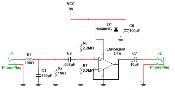
    Below is a schematic diagram for the preamp/buffer circuit being used. It was designed by team member Ryan Knepel, and serves as a buffer between the electric guitar output and the guitar pedal input.

    In the schematic above, take note of the following components and their purposes:

    • R1 and C1 are for noise.
    • C2 is a decoupling capacitor.
    • R2 is intended to prevent pops from switching the circuit on.
    • D1 is to protect against reversed polarity.
    • C6 is for power supply filtering.
    • C7 is to ensure an AC output.
    • R6 and R7 provide the power supply voltage divider.

    Implementation

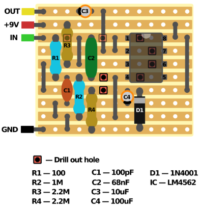
    The physical implementation of the preamp circuit was built using perforated PCB material and through hole components. A strip-board layout image may be found below:


  • Power Supply Subsystem

    Ben Jacobs05/17/2020 at 16:12 0 comments

    Description

    The Power Supply Subsystem, assigned to team member Katarina Ochoa, provides power to all the hardware components in the Pedal. It consists of two buck-boost regulator modules: one for 3.3V output and one for 5V output. Both are rated for a maximum current load of 3 Amps, and they take their unregulated input voltage from a 9 to 12V DC wall adapter.

    Block Diagram

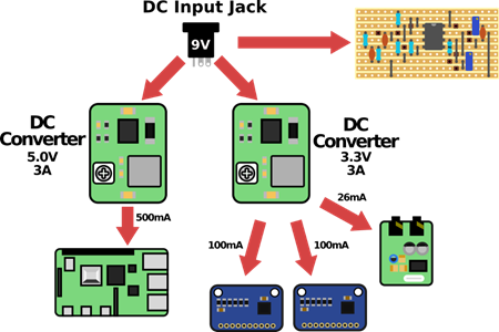
    The following block diagram shows how the Power Supply Subsystem distributes power to each of the main hardware components. From left to right, the Raspberry Pi is powered from the 5V regulator, and the ADC boards and Audio Codec take their power from the 3.3V adapter. The Preamp Circuit takes power directly from the DC jack for maximum audio headroom. The current draw values listed on this diagram are estimates from initial testing- be cautious and verify these values for yourself, because newer Raspberry Pi models usually draw more current

    Component Selection

    The power supply modules themselves were purchased instead of designed to save time and cost. They are generic buck-boost modules from an online retailer, although any low noise, high efficiency regulator circuit would work. The 3.3V module may be found here: Amazon

    Issues Encountered

    The only issue that was encountered with these power supply modules was the fact that they introduced noise into the audio chain, due to their switching nature. This was mitigated by installing 470uF capacitors across the output lines of each module to smooth out the DC waveform and suppress any emissions. See the section on Building a Hardware Prototype for more information, and a schematic diagram, as this issue was dealt with during that stage of the project.

  • Construction of a Hardware Prototype

    Ben Jacobs05/14/2020 at 19:43 0 comments

    Description

    After the individual subsystems were tested and validated, the next step was to construct a full-system prototype. This was the first step of the project (officially known as the system integration) that had to be completed off-campus due to the worldwide pandemic. Therefore, some modifications had to be made, and some tests could not be run in a formal lab environment.

    Procedure

    First, a cardboard mock-up of the Hammond 1590DD enclosure we wished to use was constructed. It matched the dimensions of the actual metal enclosure (which was not yet on hand), according to dimension drawings provided on Hammond's website.

    Next, using the cardboard prototype as a guide, a piece of perforated circuit board was cut down to a size that would fit in the enclosure. The ADC boards, the power supply modules, and the audio codec were laid out in a manner that minimized space consumption. Specifically, the ADC boards are located underneath the audio codec. This is not especially advised because i2c noise could leak into the audio, but this was not a problem we encountered. On issue that was encountered was having power supply noise on the audio. This was remedied by placing 470uF electrolytic capacitors across the regulated voltage outputs. In retrospect, linear regulators could've been used in place of buck-boost regulators to fully eliminate this noise issue, but at the cost of power efficiency.

    A 20 pin (0.1" pitch) header was used to connect the four knobs, expression pedal input, audio input and output jacks, LED and bluetooth pairing button to the board. For a very detailed layout of this pin header and the hardware PCB, please view the Hardware PCB Schematic Diagram PDF file, which is taken from Ben Jacobs' engineering notebook.

    A 40-pin IDE ribbon connector is used to connect the hardware board to the Raspberry Pi, providing the necessary i2c, SPI and GPIO connections between the two.

    Result (Preliminary Prototype)

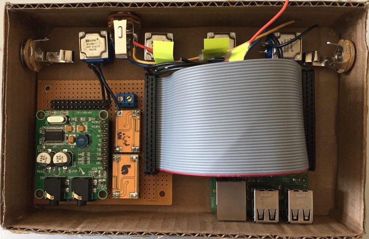
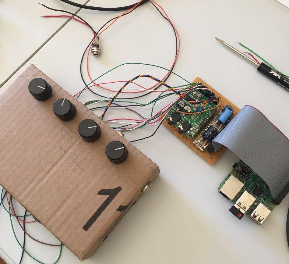
    The finished prototype in the cardboard enclosure is shown below, minus the necessary wiring harness going between the jacks, knobs and pin header. Notice that the Raspberry Pi is a tight fit. In retrospect, it may have been better to use a larger enclosure size for some wiggle room.

    Another photo of the prototype is shown below, this time from a top view, with the internals wired into the knobs and jacks, but sitting externally on the table for testing purposes. Notice that the stomp switch has not yet been implemented, because this prototype would not support physically being stomped. In the metal version, the stomp switch will fit in the gap between the PCB and the Raspberry Pi.


    Video (Preliminary Prototype Test)

    Below is an informal test of the preliminary hardware prototype. This video serves as proof that the system is working, and a more complete demonstration video may be uploaded when the pedal is in a more polished state.


    Upgrade to Aluminum Enclosure

    Once the functionality of the cardboard prototype was confirmed, it was mailed to team member Ryan Knepel, who was in charge of the final integration into a metal enclosure. He is also scheduled to integrate the stomp switch, LED, and preamplifier circuit.

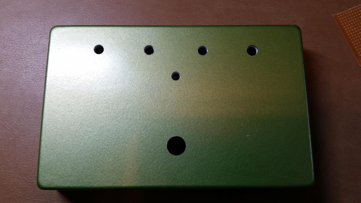
    Below is a photo of the aluminum enclosure, which has been painted (a green color was not our first choice, but it sufficed because of limited access to hardware stores at the time) and drilled.

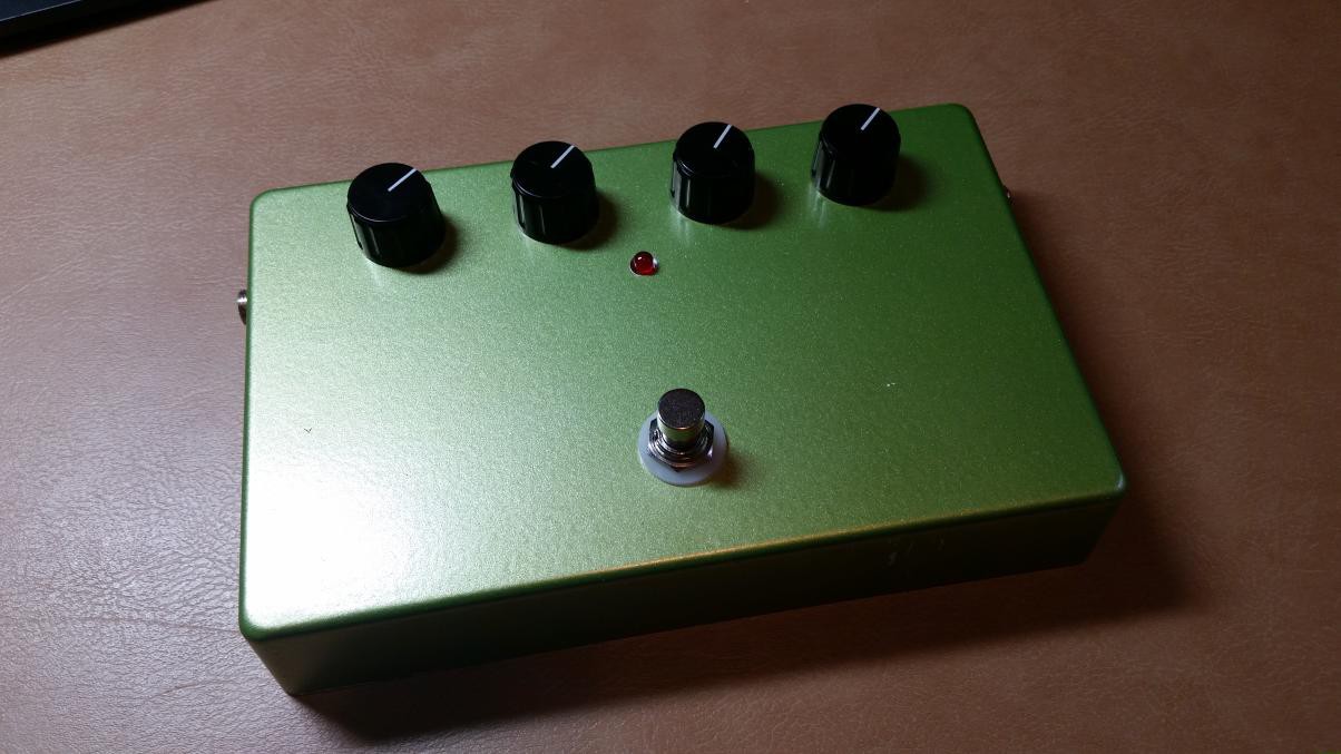
    Below is another image of the aluminum enclosure, now with the various jacks, knobs other hardware elements mounted in the holes. This photo gives a good idea of how the final product will look (much more professional than the cardboard prototype!).

  • Automating the Subsystems (Scripting)

    Ben Jacobs05/12/2020 at 16:37 0 comments

    Overview

    In order for the pedal system to function with no human-interaction after booting the Raspberry Pi, some actions need to be automated with scripts. Namely:

    • PureData must be loaded at boot with the effect file to be opened as a runtime parameter
    • A command should be run that enables Bluetooth on the Raspberry Pi (App Subsystem)
    • The Human Interface Python script that handles the ADCs should be loaded at boot

    Running Scripts with Crontab

    To accomplish this list of tasks with automation, bash scripts were employed, in conjunction with a Linux tool called Crontab. Crontab allows editing a system file (also called crontab) which allows user entry in a specific format, which is then decoded by the OS into instructions for it to run certain terminal commands at certain times of day, or in our case, when certain events occur, like shutdown or boot. You can familiarize yourself with Crontab here: Ubuntu Cron How-To.

    Below are the three entries in our team's Crontab file. The first line runs PureData and the second line runs the Human Interface Python script. Note the '@reboot' statement preceding every command. This says "run this line when the OS boots". Also notice the '&' character after every line. This says "do not wait for a return from this command, move on to the next one without hanging the terminal".

    If you are duplicating this project for your own use, make sure to include the proper name and paths to these files- your file-paths or script names could be different.

    @reboot sudo bash /home/patch/Scripts/run_pd_boot.sh &
    
    @reboot sudo python3 /home/patch/Scripts/knob_send_v1_3.py &

    Script Spotlight: run_pd_boot.sh

    The run_pd_boot.sh script handles opening the PureData DSP engine and starting audio processing. Below is the full code of this script.

    #!/bin/sh
    sudo amixer -c 0 cset numid=4 on
    sudo pd -rt -nogui -r 48000 /home/patch/Documents/Pd/effect.pd &


     In the code above, the first line tells the OS that this is a Bash Script. The second line is a call to alsamixer (the ALSA sound level and mixing tool). The option '-c 0' stands for "Use card #0", which should be the WM8731 Codec from the Audio Subsystem.

    The option "cset numid=4 on" causes ALSA to enable control number 4 on card 0. In our case, this vaguely named control maps to the "Line Input Mux". This is a feature of the WM8731 card which allows a user to choose whether audio input comes from the microphone input, or the line level input. For our purposes, we want the line input, so we set this mux control to 'on'.

    Finally, the third line opens PureData. Notice that it is prefaced with "sudo" to run as the root user. The '-rt' option stands for "real time audio", the '-nogui' option tells PureData to run without a graphical interface (you may wish to omit this option if you're still debugging using the desktop environment so that you can actually see the PureData window come up). Lastly, the file path to the effect that should be run is provided.

    This script doesn't need to be run through crontab, either. It can be called manually from the terminal during a normal desktop session for debug purposes, too. In fact, it is encouraged to always launch PureData from this script, because the 'amixer' command preceding it ensures that the system audio is set up properly (avoids bugs).

    Script Spotlight: knob_send_vX_X.py

    This is the Python script which handles the human interface, and links the physical knobs to the PureData DSP engine. This script is examined in detail under the Project Log for the Human Interface Subsystem.

  • Human Interface Subsystem

    Ben Jacobs05/02/2020 at 14:29 0 comments

    Subsystem Description

    The Human Interface Subsystem, assigned to team member Ben Jacobs, allows for input from various analog hardware controls. These inputs are routed to the PureData DSP engine through a Python script to change effect parameters 'on the fly'. Our hardware prototype has four hardware knobs, and one expression pedal input. This could be expanded by three inputs with the existing ADC hardware, for up to 8 total analog inputs.

    The subsystem is comprised of two ADS1015 Analog Digital Converter boards, which communicate with the Raspberry Pi over the same i2c bus as the Audio Codec. As mentioned above, a Python script handles this communication, value averaging and thresholding, and the routing of the digital values to PureData. The potentiometers that are used for the four knobs in our hardware prototype are 30k Ohms linear taper, but depending on your preference, any sufficiently high value would work (10k - 100k). Remember that the lower the resistance value, the more wasted power there will be due to increased current.

    Subsystem Bill of Materials

    • 2x ADS 1015 ADC boards (Adafruit)
    • 4x 30k Ohm Linear Potentiometers
    • 1x Stereo 1/4" Jack (Exp. Pedal Inp.)
    • Jumper Wires
    • Medium breadboard

    Subsystem Hardware Connections

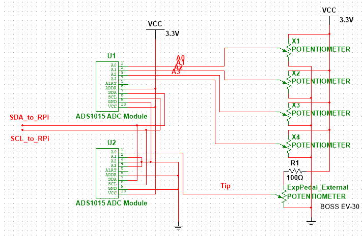
    Below is a block diagram showing the connections to the Raspberry Pi. Notice that these connections are made over the same i2c bus as the Audio Codec uses. Both devices on the bus will have different addresses. Also notice that there are three free channels on the second ADS 1015 device (channels 6 through 8) that could theoretically be used for more human interface device inputs with minor software modifications. Make note of the 100 Ohm current limiting resistor on the expression pedal VCC connection. This is to reduce current inrush when the pedal is plugged in.

    Subsystem Software

    To accompany the hardware for this subsystem, there are two main software pieces to complete the path from the hardware knobs to the PureData DSP engine. These come in the form of a Python script called KnobSend, and a PureData object called Knobs. These files will be available for download under the files section of this site.

    The Python Script

    The purpose of the Python script is to read the ADC devices over the i2c bus and do some averaging and threshold math on the returned values so that they end up ranging between 0 and 1, which makes them useful for modifying PureData patch (effect) parameters.

    The script makes use of the following Adafruit libraries, which must be installed on the Raspberry Pi. The following links have useful information on completing those installs.

    CircuitPython (busio)

    ADS1015-specific library module for CircuitPython

    The full code of the Python script can be found in the files section of this site, but a few key snippets will be examined here. The snippet below sets up the i2c connection for use in the rest of the script. Notice the i2c addresses are hard coded here in decimal (72 = 0x48, for example).

    #Adafruit Library Code
    i2c = busio.I2C(board.SCL, board.SDA)
    import adafruit_ads1x15.ads1015 as ADS
    from adafruit_ads1x15.analog_in import AnalogIn
    
    #Define ADC object
    ads1 = ADS.ADS1015(i2c, address=72) #The ADC with the knobs (0x48)
    ads2 = ADS.ADS1015(i2c, address = 73) #The ADC with the expr. pedal (0x49) 
    

    This snippet sets some parameters for the rest of the script, called avgs (averages) and threshold. The averages parameter sets how many readings should be taken for every final value that is outputted. The readings are averaged to reduce parasitic noise in the readings. The default is 10.

    The threshold parameter sets the minimum delta (change) between two values (post-averaging) that is necessary for the script to consider a knob to have been turned. This further reduces noise, and prevents the system from getting bogged down due to constantly sending new values, even if they aren't substantially different from the last value. The default is a minimum delta of 0.01...

    Read more »

  • Rpi OS, PureData, Audio Codec Subsystem

    Ben Jacobs04/29/2020 at 22:18 0 comments

    Subsystem Description

    This subsystem contains contributions from team members Chad, Katarina, Ryan and Ben J.

    The Raspberry Pi 3B+, for all it's excellent features, does not have a built in audio input. To remedy this and get the analog guitar audio into the RPi for processing, as well as to provide a HiFi audio output, an audio codec device was used. An audio codec is a device that interfaces digitally with a processor to provide analog audio capabilities. The main components that go into a codec are an ADC, a DAC, and some sort of filtering. The codec that was used in this project in specific was the Wolfson 8731, which is available on a dev-board for convenience.

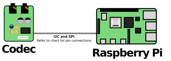
    The Wolfson 8731 operates on the i2C interface (for low speed, general purpose communications, eg. setting volume) and the SPI/I2S interface (for audio data transfer). Using open source drivers, the WM8731 appears to the Raspberry Pi's Linux operating system as a normal sound card in the ALSA sound manager tool (alsamixer).

    The audio codec dev-board may be sourced at the following website for a cost of $19 (as of April 2020): https://www.mikroe.com/audio-codec-proto-board

    Subsystem Bill of Materials

    • Raspberry Pi 3B+ (Amazon): $35
    • WM8731 Proto Dev-Board (Mikroe): $19
    • Female-Femal Jumper Wires (Adafruit): $3.95
    • Medium breadboard

    First Step - Loading an OS on the Raspberry Pi

    This project assumes you are using the PatchBoxOS on your Raspberry Pi. PatchBox is an OS that supports Real-Time audio, and is rather lightweight, compared to Raspbian or other common OSes for the Pi. If you use another debian-based OS, be prepared to possibly encounter audio latency issues.

    A download link and install instructions for PatchBox may be found on their website: https://blokas.io/patchbox-os/

    Subsystem Hardware Connections

    With the OS installed on the Raspberry Pi, you may begin making hardware connections for the Audio Codec Subsystem. Below is a block diagram of the codec subsystem. Notice the connections to the RPi over I2C and SPI interfaces.


    Below is a table showing the connections between the Raspberry Pi and the WM8731 Codec board. For the puprose of this site, this information was taken directly from the following webpage: https://www.fredrikolofsson.com/f0blog/?q=node/656

    proto               raspberry
    -----                -----
    sck                  rpi 12
    miso                 rpi 38
    mosi                 rpi 40
    adcl+dacl            rpi 35  //both proto pins go to the same rpi pin
    sda                  rpi 3
    scl                  rpi 5
    3.3v                 rpi 1
    gnd                  rpi 6 

    It is important to note that for the time being, the codec may be powered by the 3.3V pin on the Raspberry Pi, but in the final prototype, the codec and the Raspberry Pi are being powered by the Power Supply Subsystem (details provided in that section).

    Subsystem Software Configurations

    Before the WM8731 codec will be recognized by the Linux operating system on the Raspberry Pi, some software configuration was necessary. Although the same page used for the hardware connections reference (the blog of Fredrik Olofsson) contains software setup instructions, it was found that issues with audio dropouts and general instability were remedied by following the Github page for the TerminalTedium project, which also uses the WM8731 in conjunction with a Raspberry Pi: https://github.com/mxmxmx/terminal_tedium/wiki/setting-up-linux

    The difference between these two sites is in which kernel module is being loaded to handle communication with the codec. The TerminalTedium page recommends loading the rpi-proto module, which was found to work best, as it appears to be a module built into Linux which was made specifically to be compatible with the WM8731.

    Kernel modules are loaded at boot on the Raspberry Pi by modifying the config.txt file, located in the /boot/ directory. The following code snippet shows the modification necessary to this file in order to load the necessary module....

    Read more »

View all 7 project logs

Enjoy this project?

Share

Discussions

Similar Projects

Does this project spark your interest?

Become a member to follow this project and never miss any updates