cprossu
-
Capricorn tubing and Pi 08
09/08/2020 at 15:02 • 0 commentsI was intending to see how long the PTFE tubing would last in use, however I noticed quite a few improvements with my own printers when I installed capricorn tubing on my own machinei, so instead of waiting it out I decided to beat the rush, get some tubing, and set about installing it. I ordered 2 Meters and figured that would take care of both machines. In fact I had enough to do 3 Ender 5's, which is pretty cool.
![]()
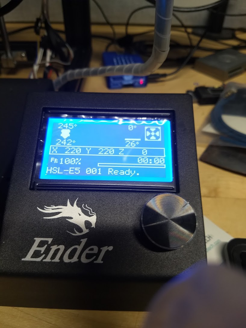
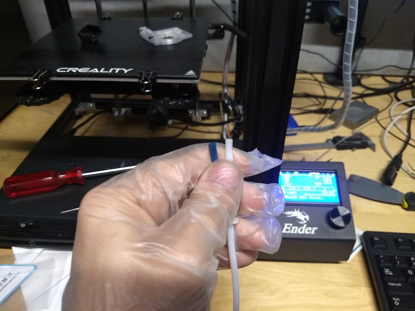
There was ABS in the printer left from the previous print, and since the machine was all together my first operation was to heat the nozzle up so I wouldn't have a bad time removing anything.
![]()
I then pushed a little of the ABS through the nozzle and pulled out the filament.
![]()
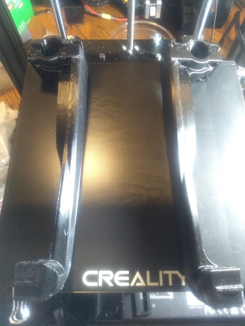
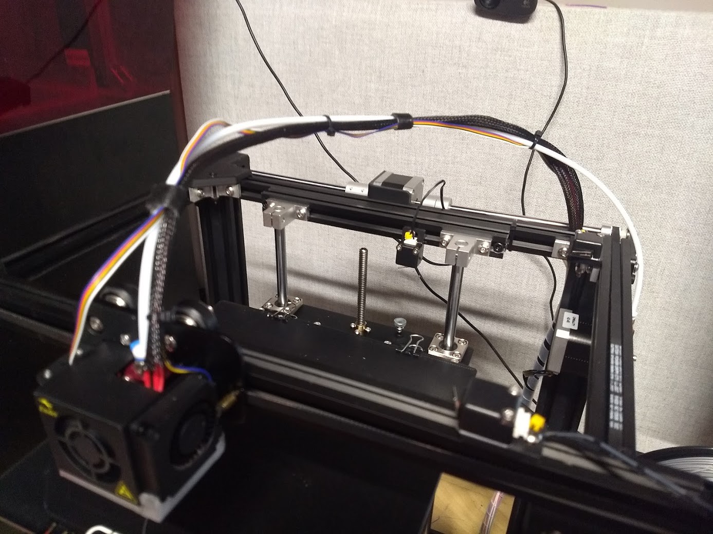
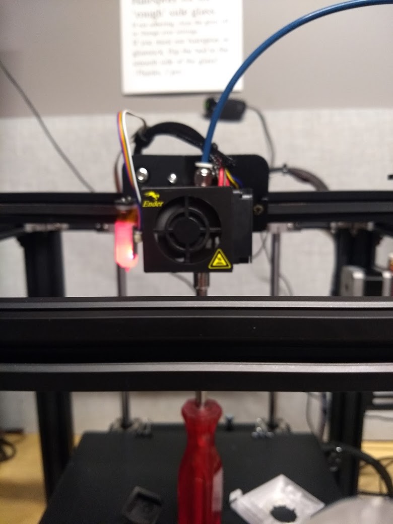
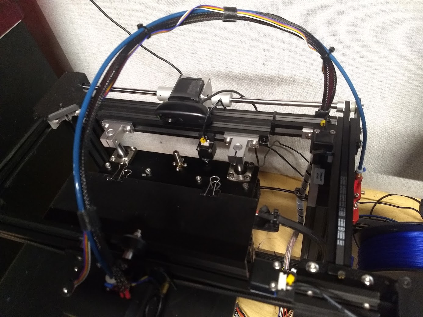
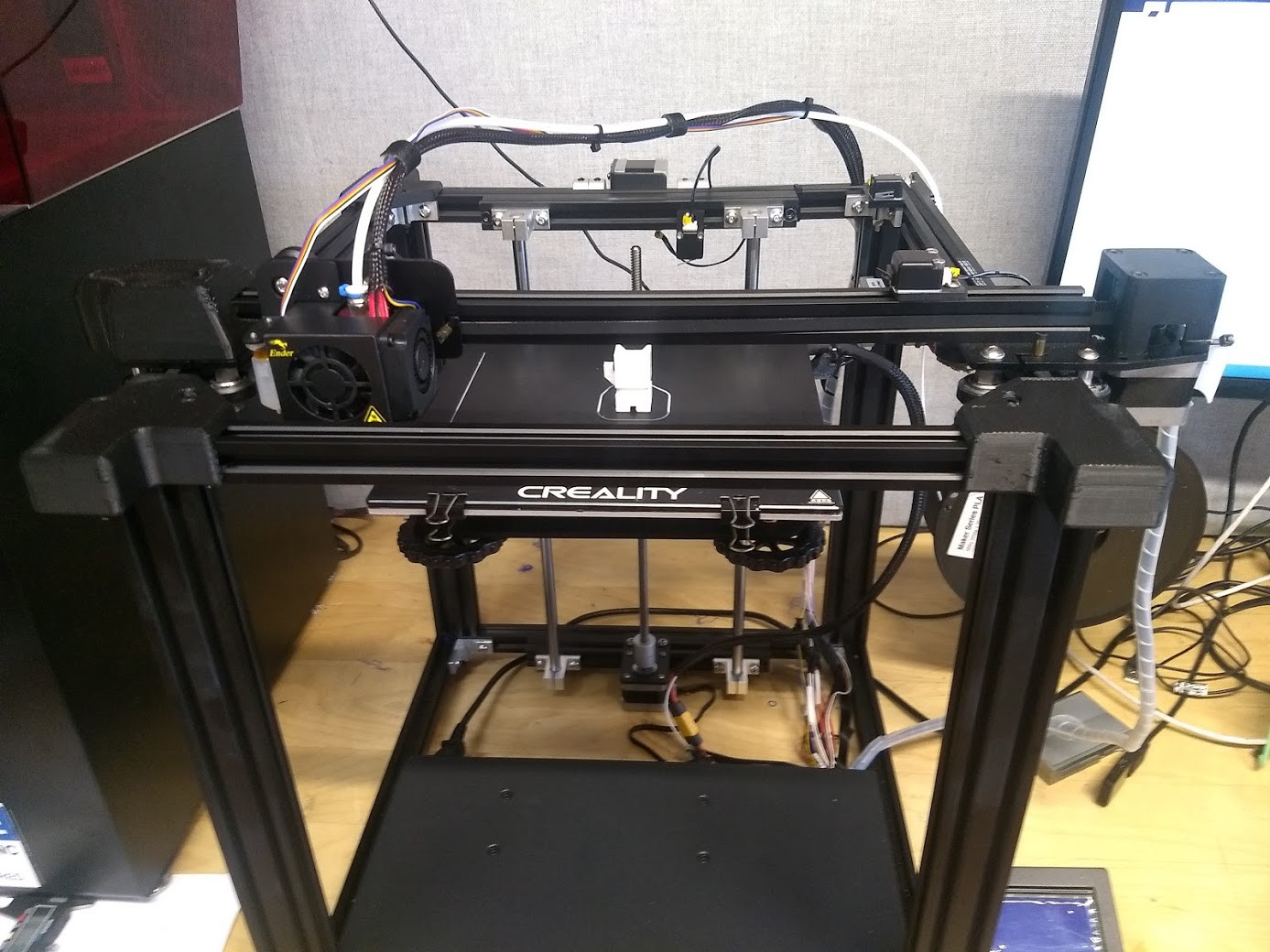
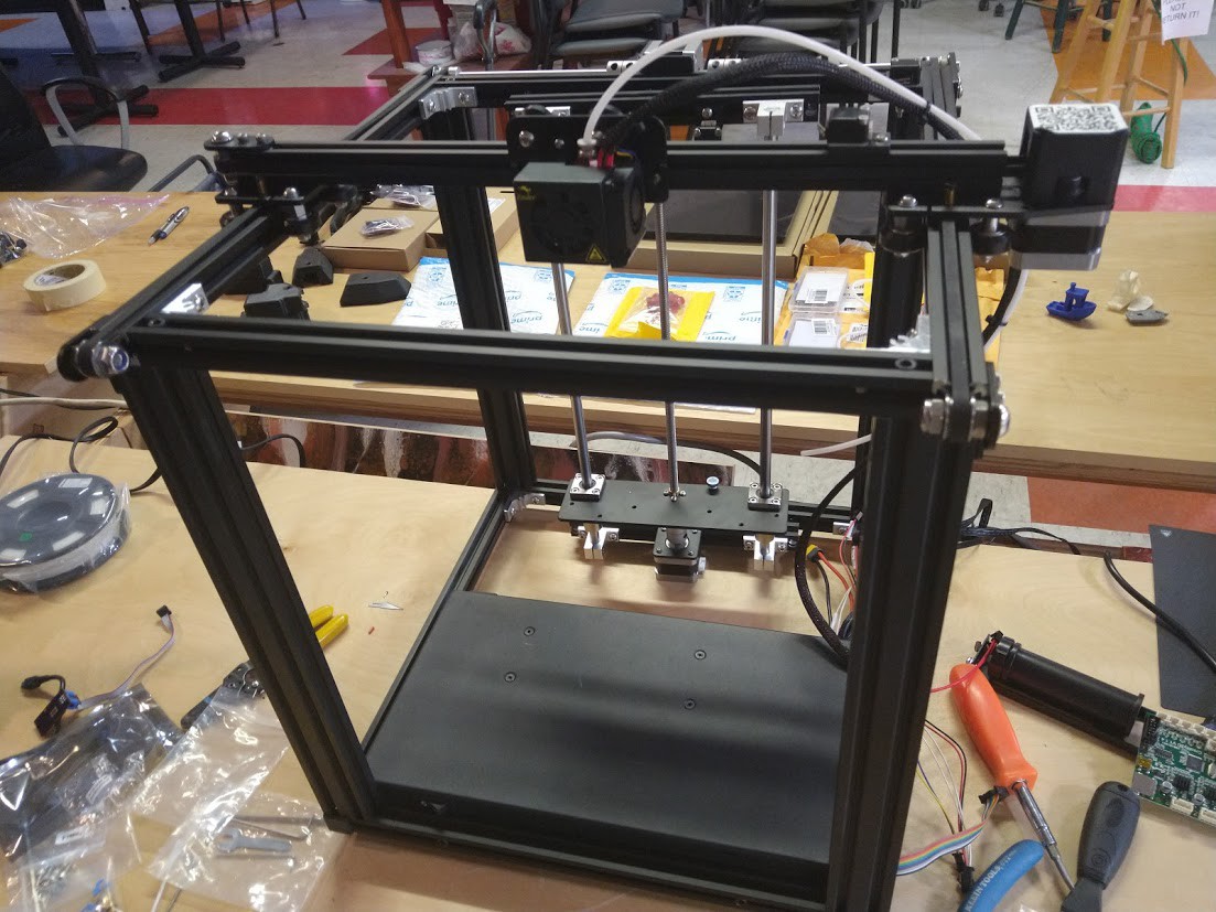
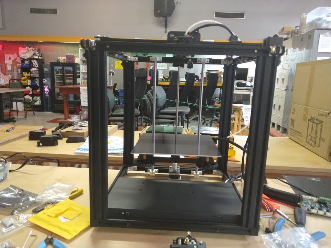
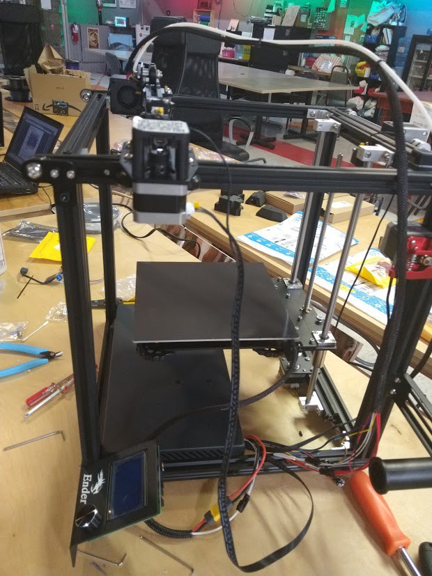
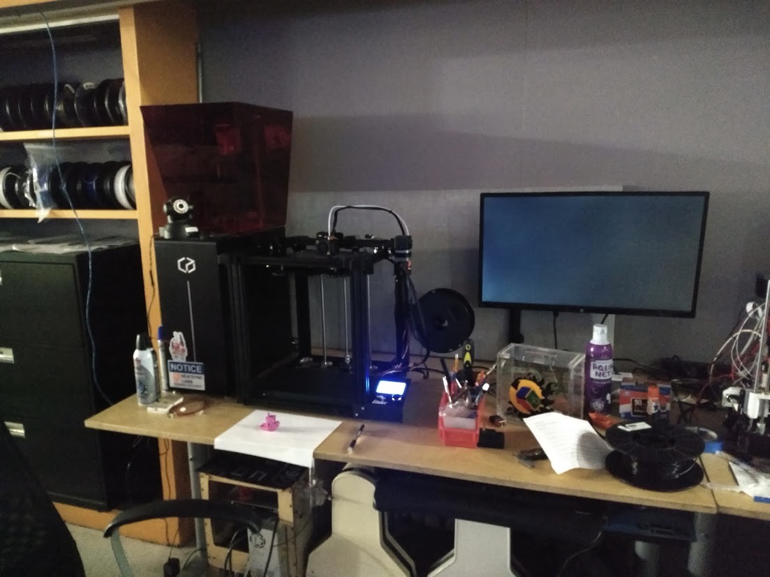
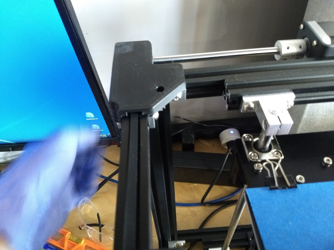
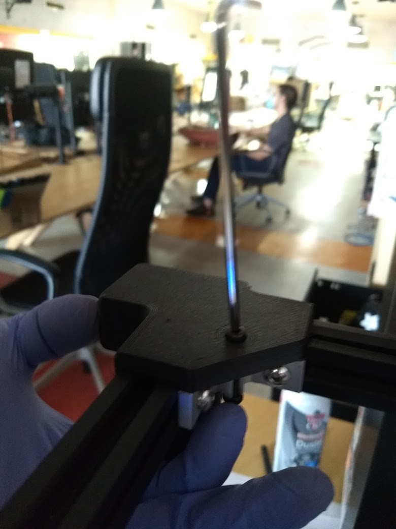
Overview of the machine, we're going to be replacing the white tube going from the print head/extruder to the extruder drive in the back right of this photo.
![]()
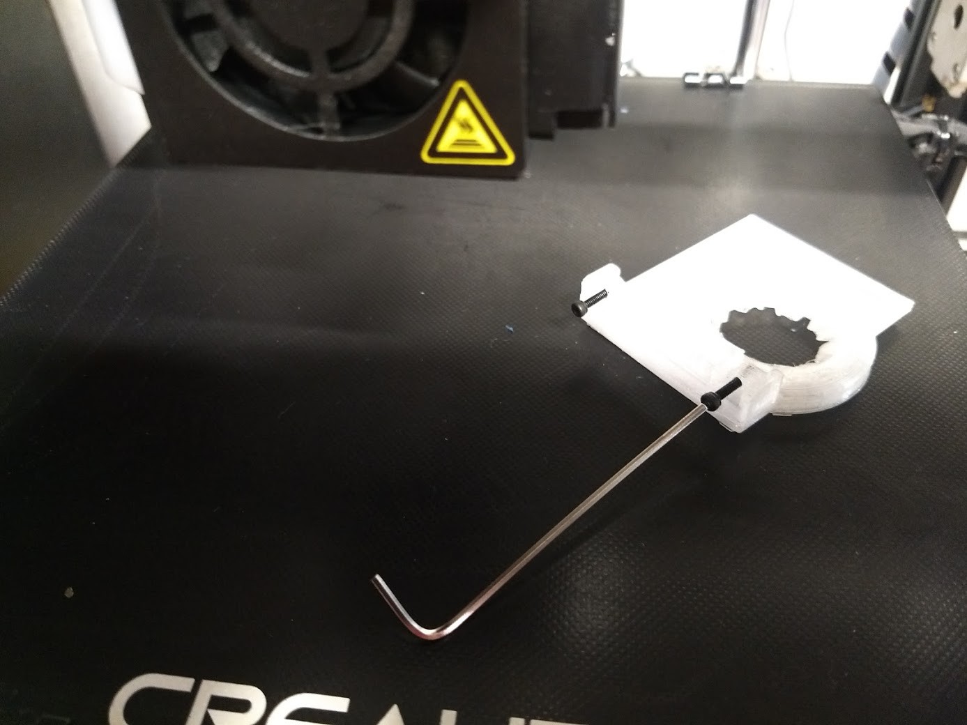
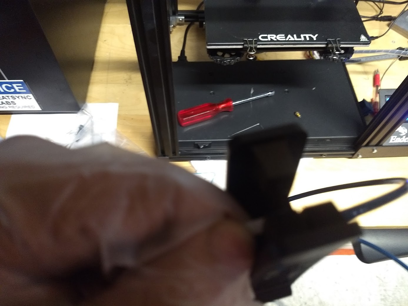
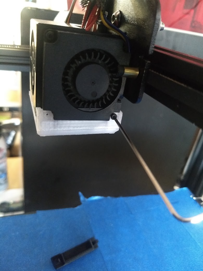
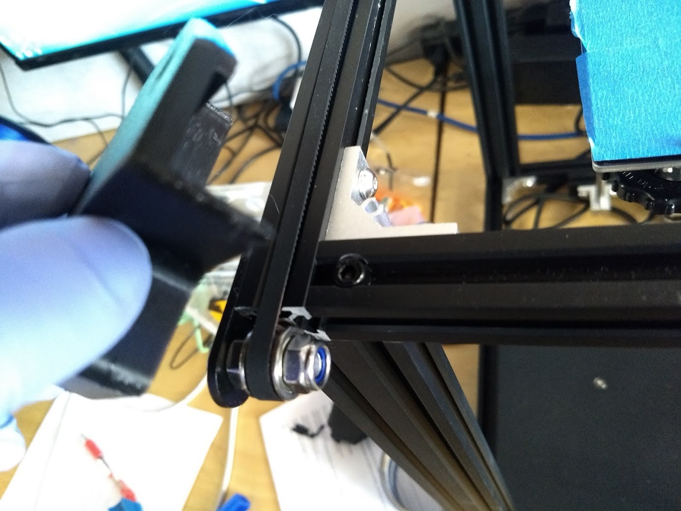
Remove our snazzy fan shroud for now, it's going to be in the way of what we need to do next.
![]()
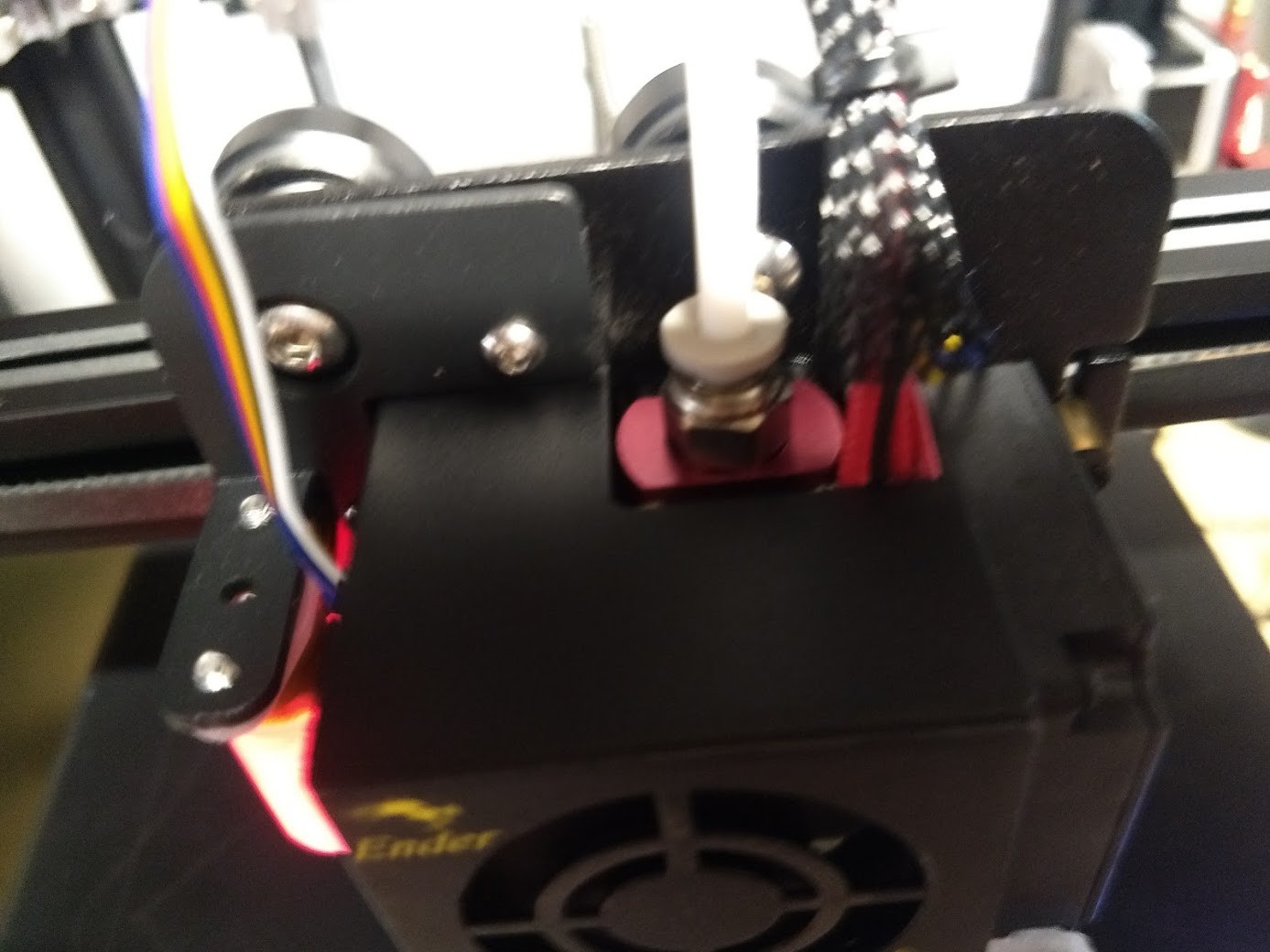
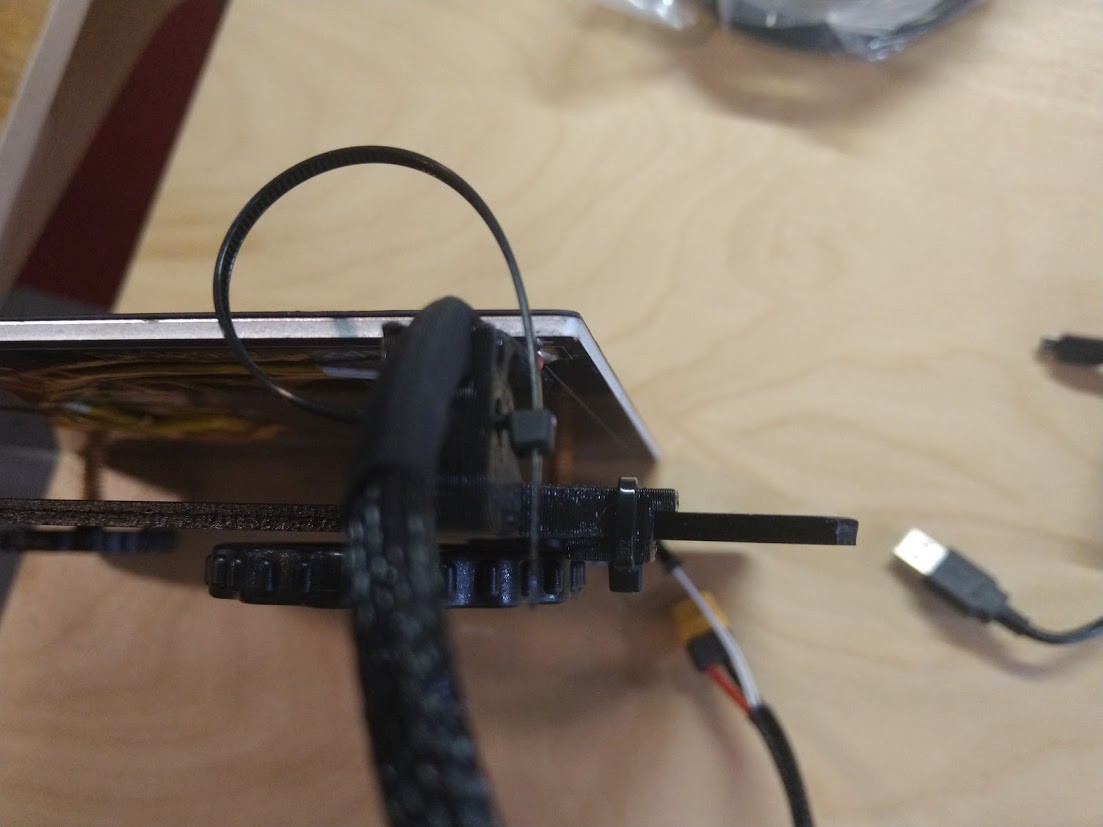
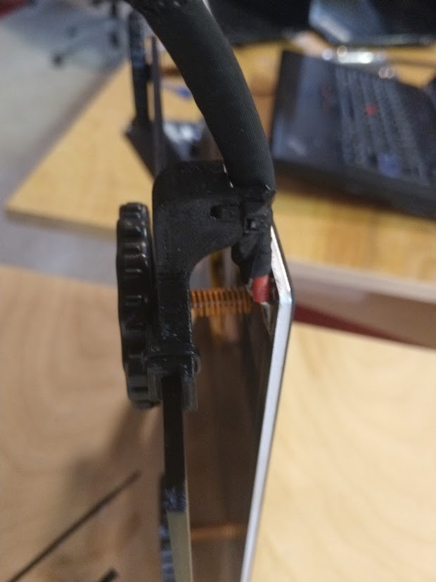
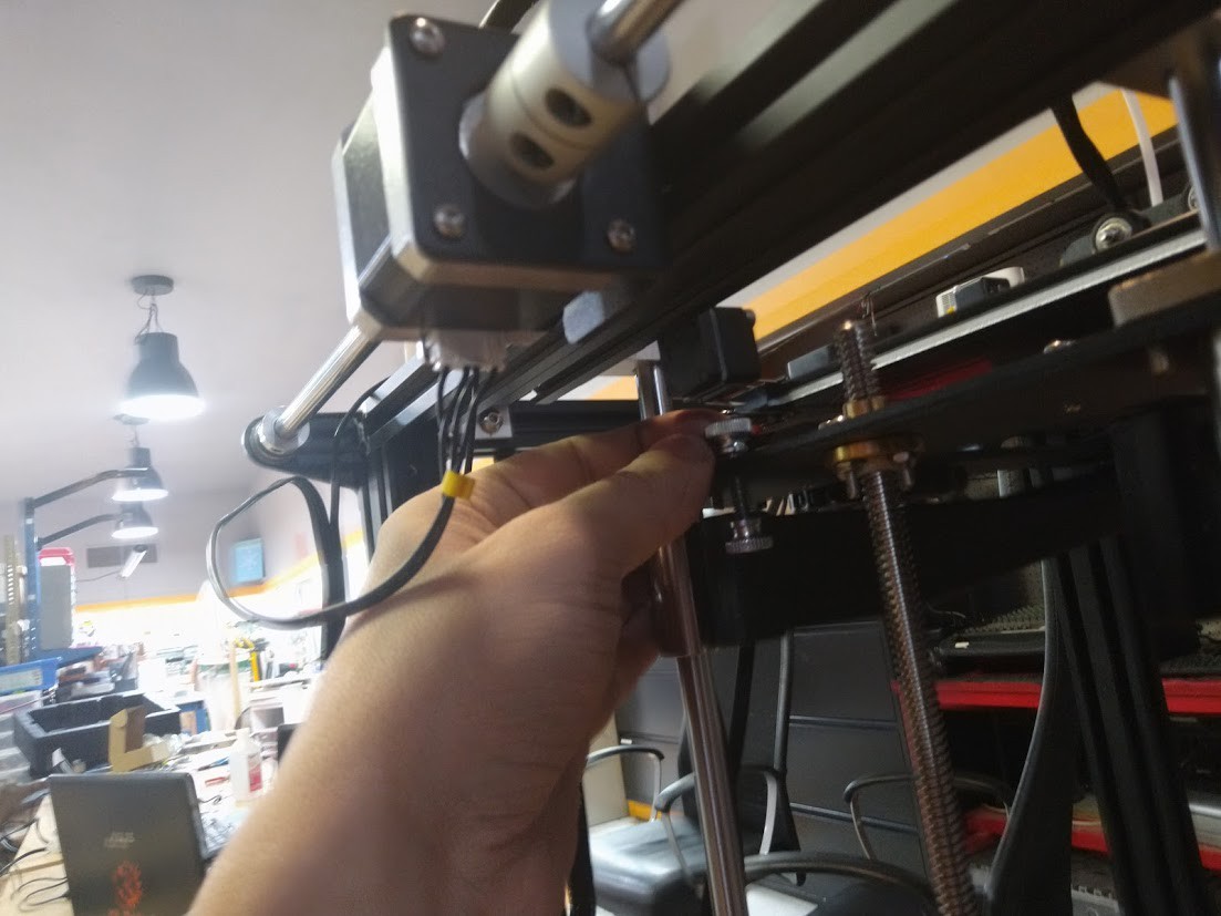
Loosened the nut on the compression fitting for the heatbreak/extruder, which allowed me to pull the PTFE right out and easily.
![]()
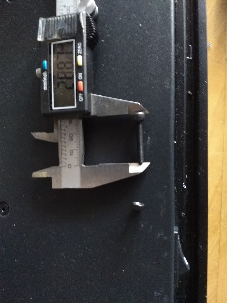
I used the old PTFE tube for 2 things: 1) To measure out how much capricorn tubing I'd need (I added 1/8" for good luck), and 2) to push out the debris inside the extruder heatbreak once I pulled the nozzle off.
![]()
The kit I got came with a tubing cutter, so I used it to cut the tubing to length, making care to keep it flush and as straight as possible.
![]()
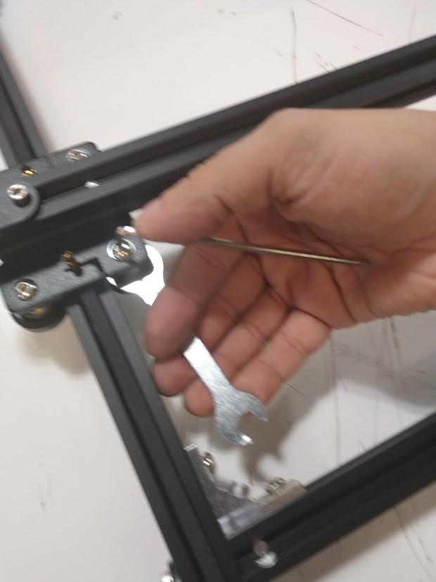
I used a 1/4" hex nut driver to remove the nozzle for clearing, and I also used it to hold the nozzle in a good position when working with inserting the new capricorn. I inserted the capricorn's most parallel/flat end into the heatbreak, and I extended the new tubing below where it needed to be. I threaded the compression fitting on lightly and then pushed it up using the pressure of the nozzle being threaded in from underneath. I wanted to make sure the nozzle and the end of the tubing had as little of a gap as possible, and then tightened both the nozzle and the compression fitting up. I do not recommend using the included nozzle wrench with your printer, it will cause damage to your nozzles especially if they are brass. A good 6 point socket or nut driver works wonders on these nozzles.
![]()
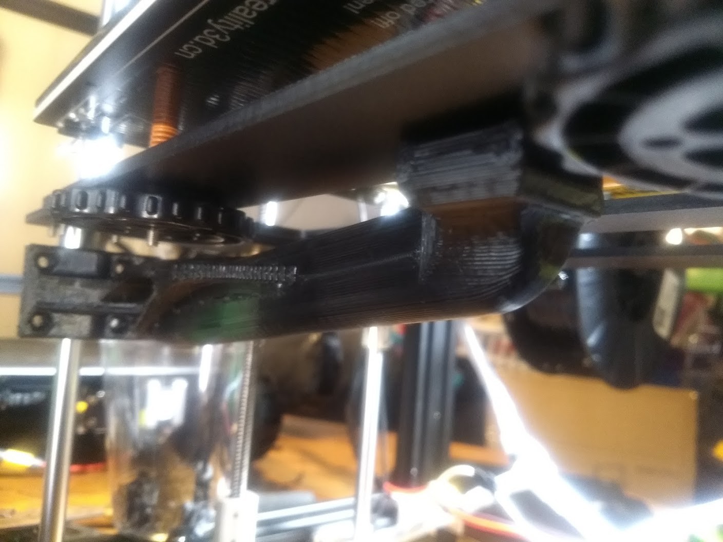
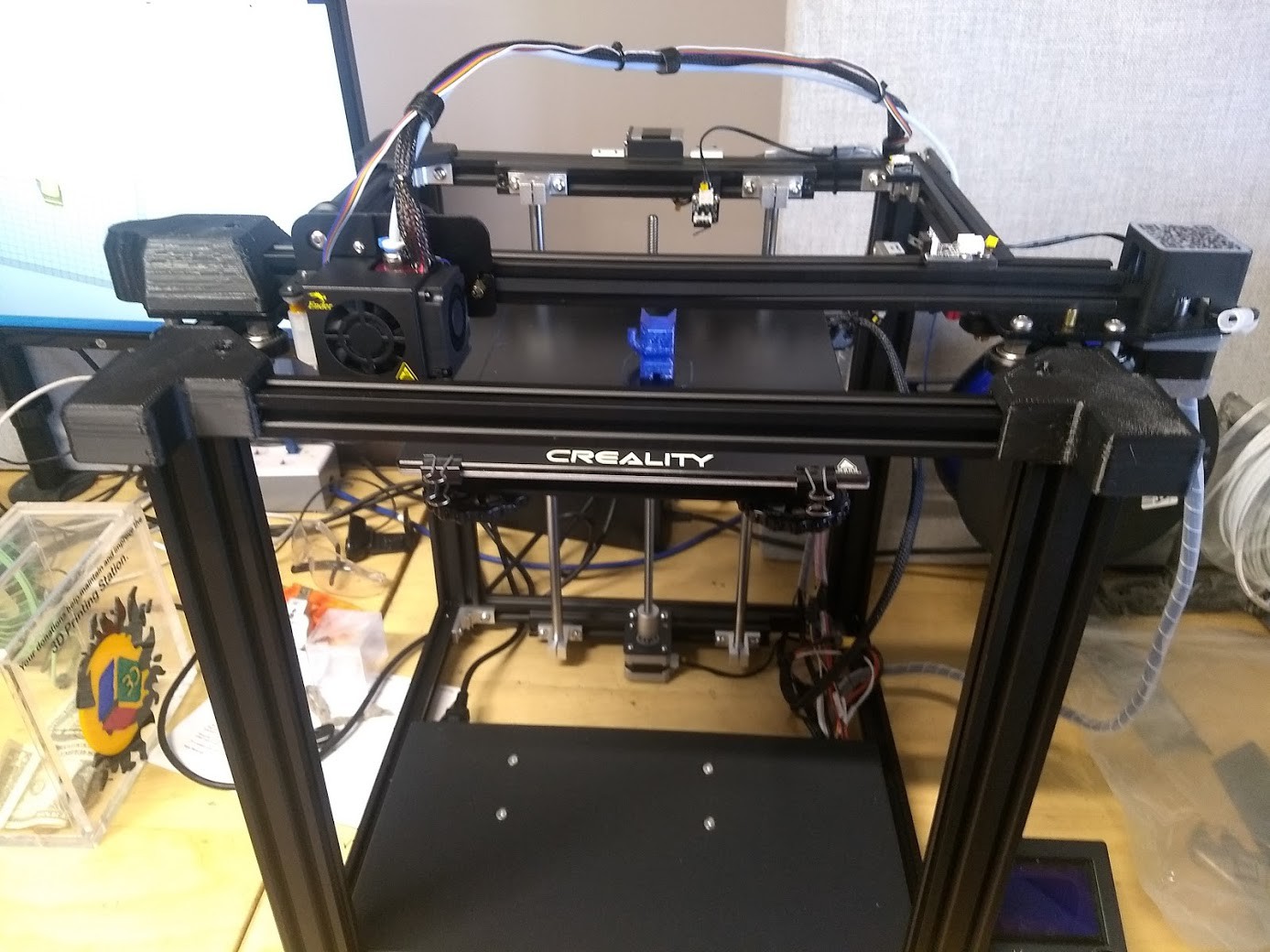
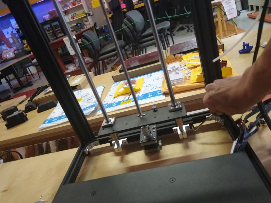
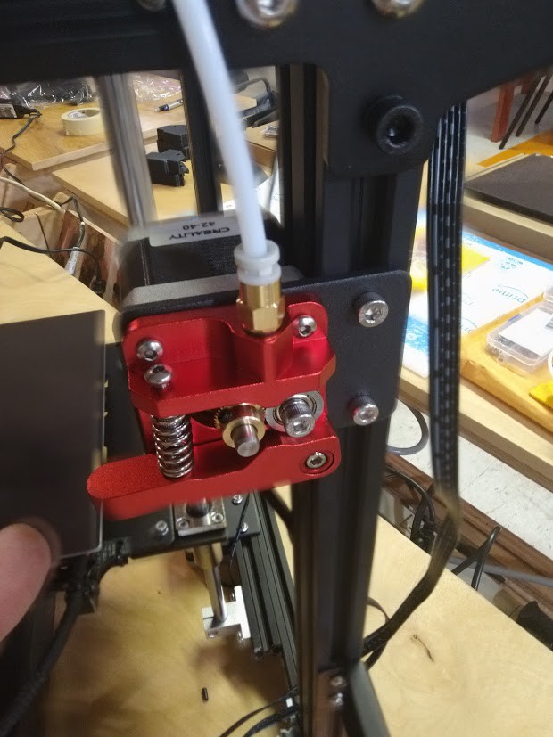
I fed the capricorn tubing through all the existing tie wraps since I knew it was just a little smaller than the PTFE tubing that came before it, making it easy. You really should replace your tie wraps, I was just being lazy and not setting a good example here.
![]()
We picked up a couple of Raspberry Pi 4 2GB boards to use for Octoprint since all the 3B's were out of stock so long, and the project dragged on until most of the problems in Octoprint relating to the 4 were cured (YAY!)
![]()
![]()
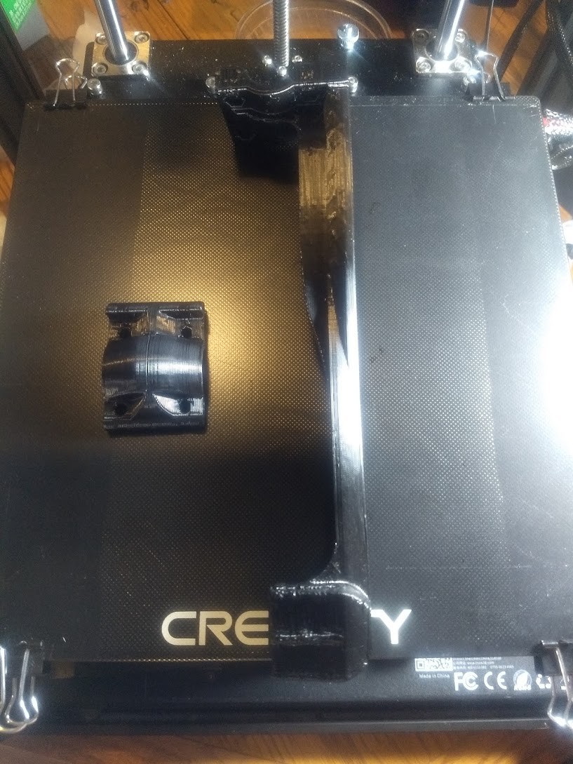
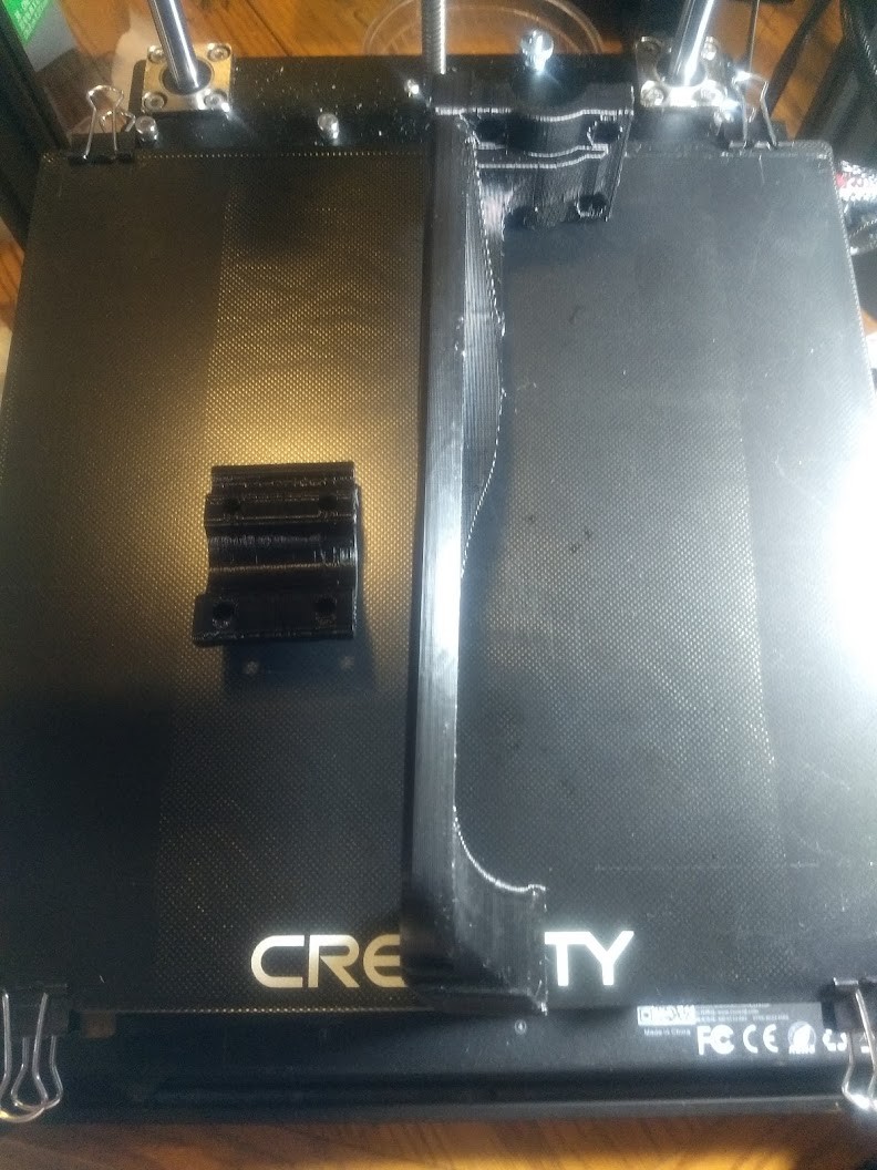
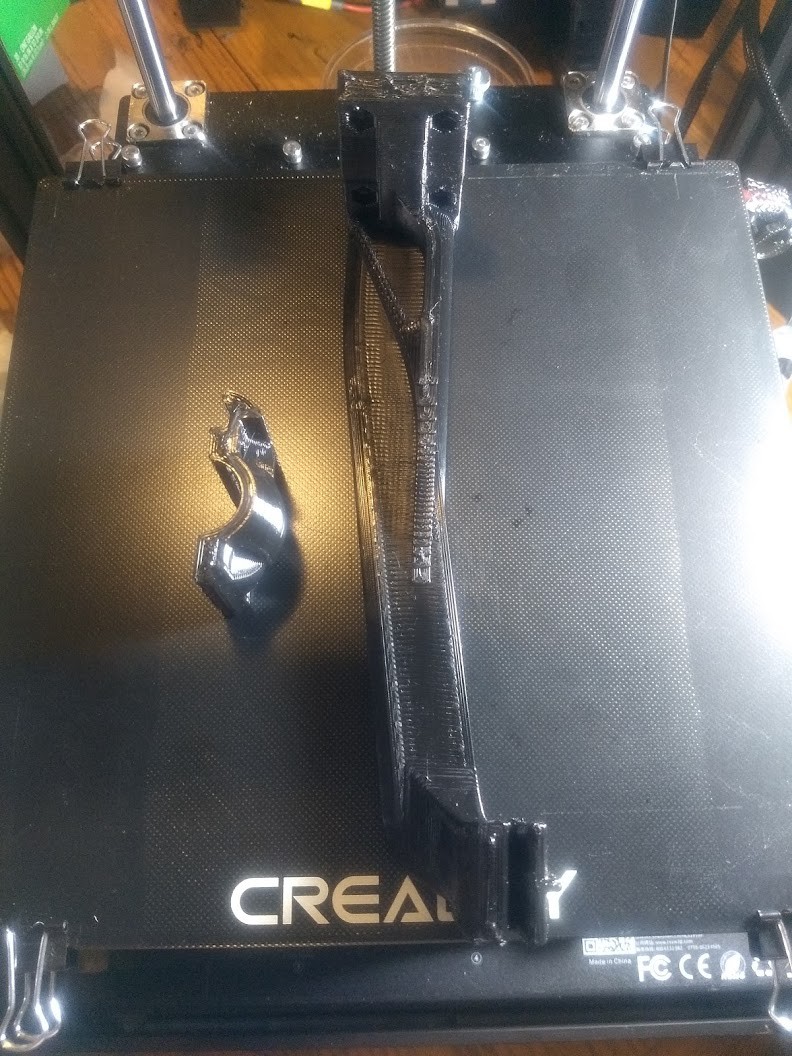
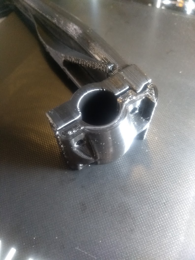
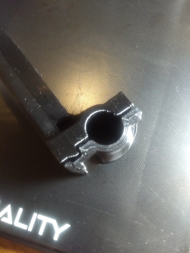
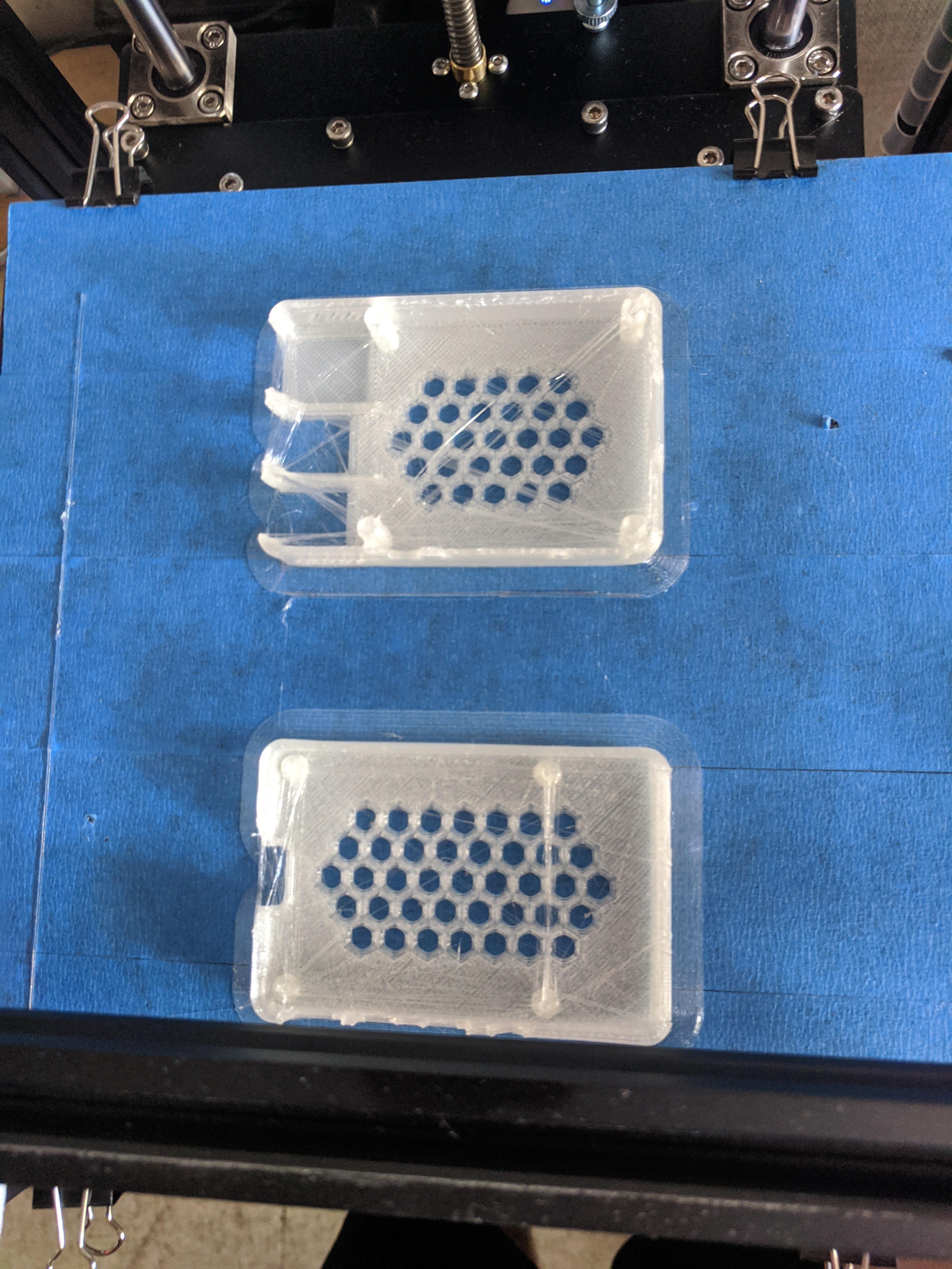
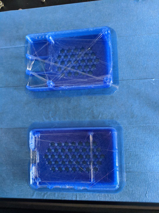
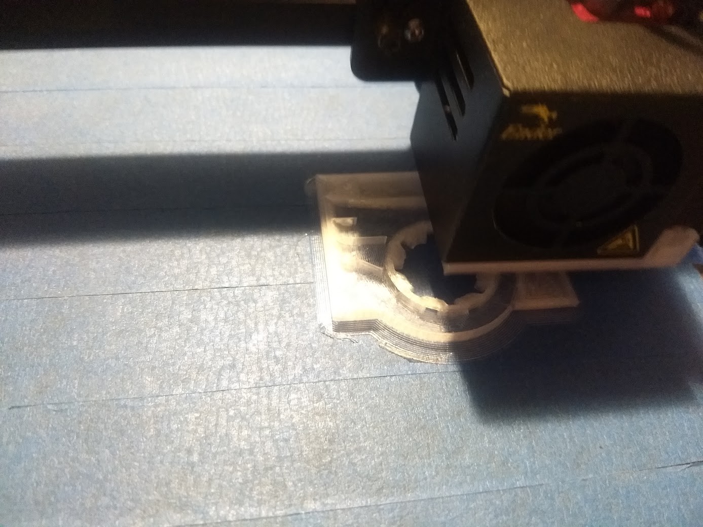
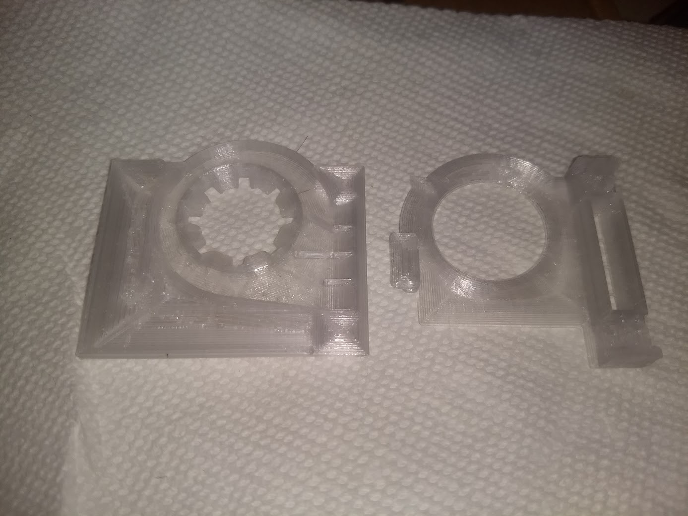
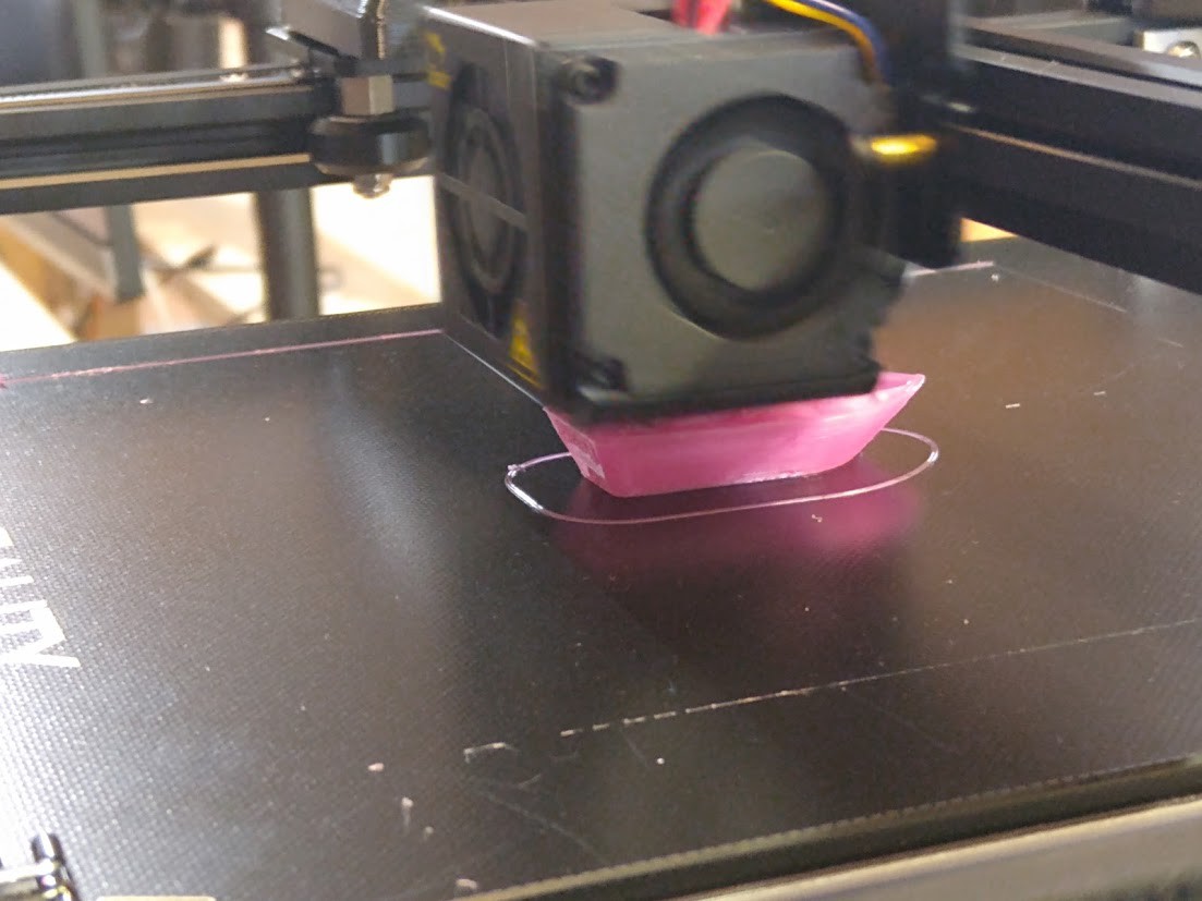
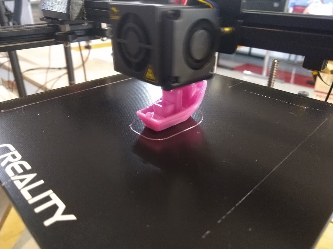
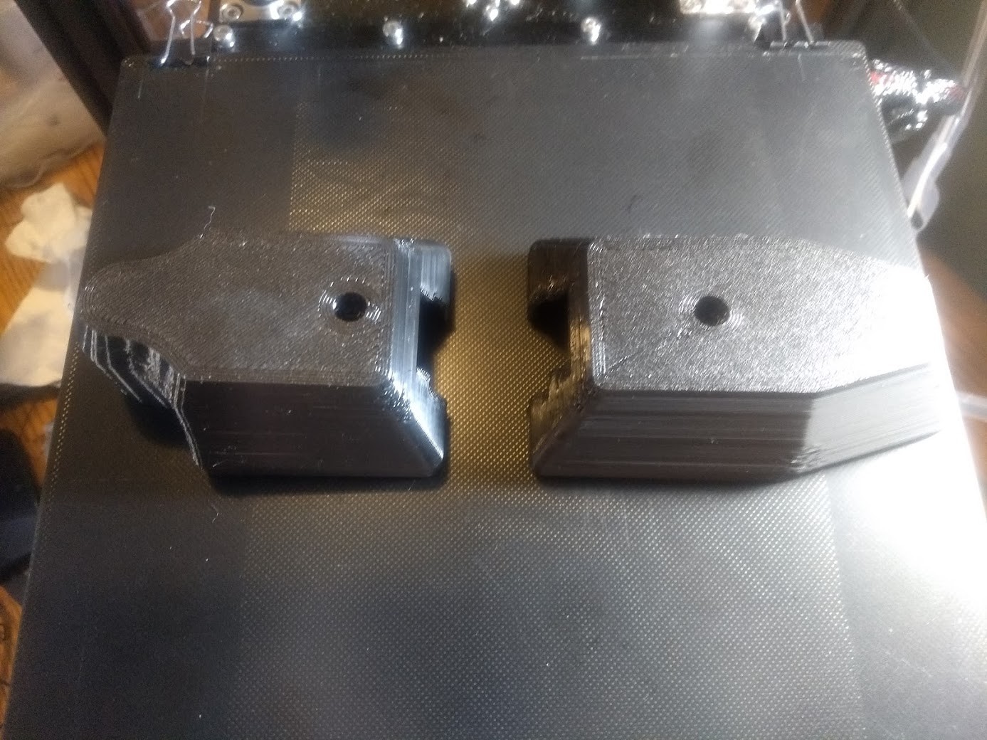
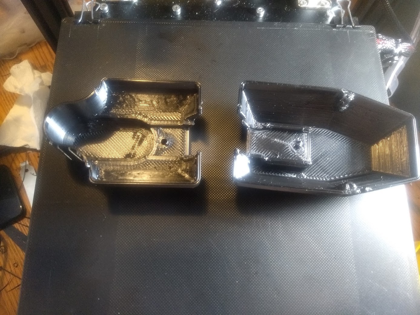
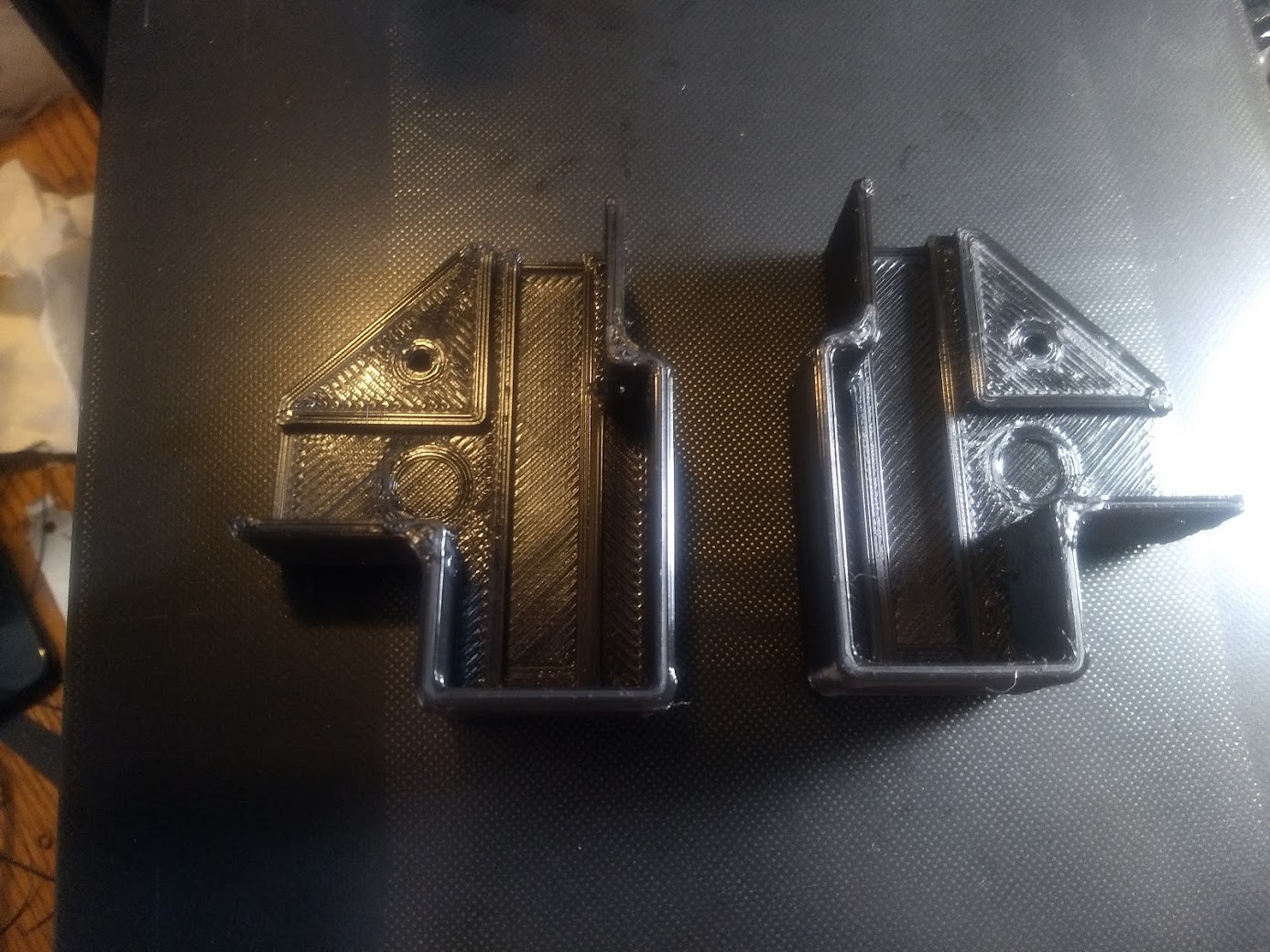
I used the printers to make some Pi 4 cases (prior to installing the new capricorn boden tube). Clearly I am going to have to work on the cura profiles, or figure out why we're getting this much stringing. Guessing my retraction is out of whack. Still fun to see both printers are making exactly the same defects!
I downloaded OctoPi https://github.com/guysoft/OctoPi and used Etcher (https://sourceforge.net/projects/etcher.mirror/) from a windows box to install the OctpPrint image onto a 16GB MicroSD card for both machines. I edited the octopi-wpa-supplicant.txt file on the BOOT partition of the MicroSD card and uncommented the lines for the network I was going to use and the country I was in (In this case the WPA2 sections and the US country code). This allowed me to get them on the network and configure them. I should do an in depth post on that, however I did not take enough pictures or grab screenshots when I did it last night. Also we had a couple of Logitech C270 web cams laying around, so I just set those on the printer for now until we get some Pi cameras.
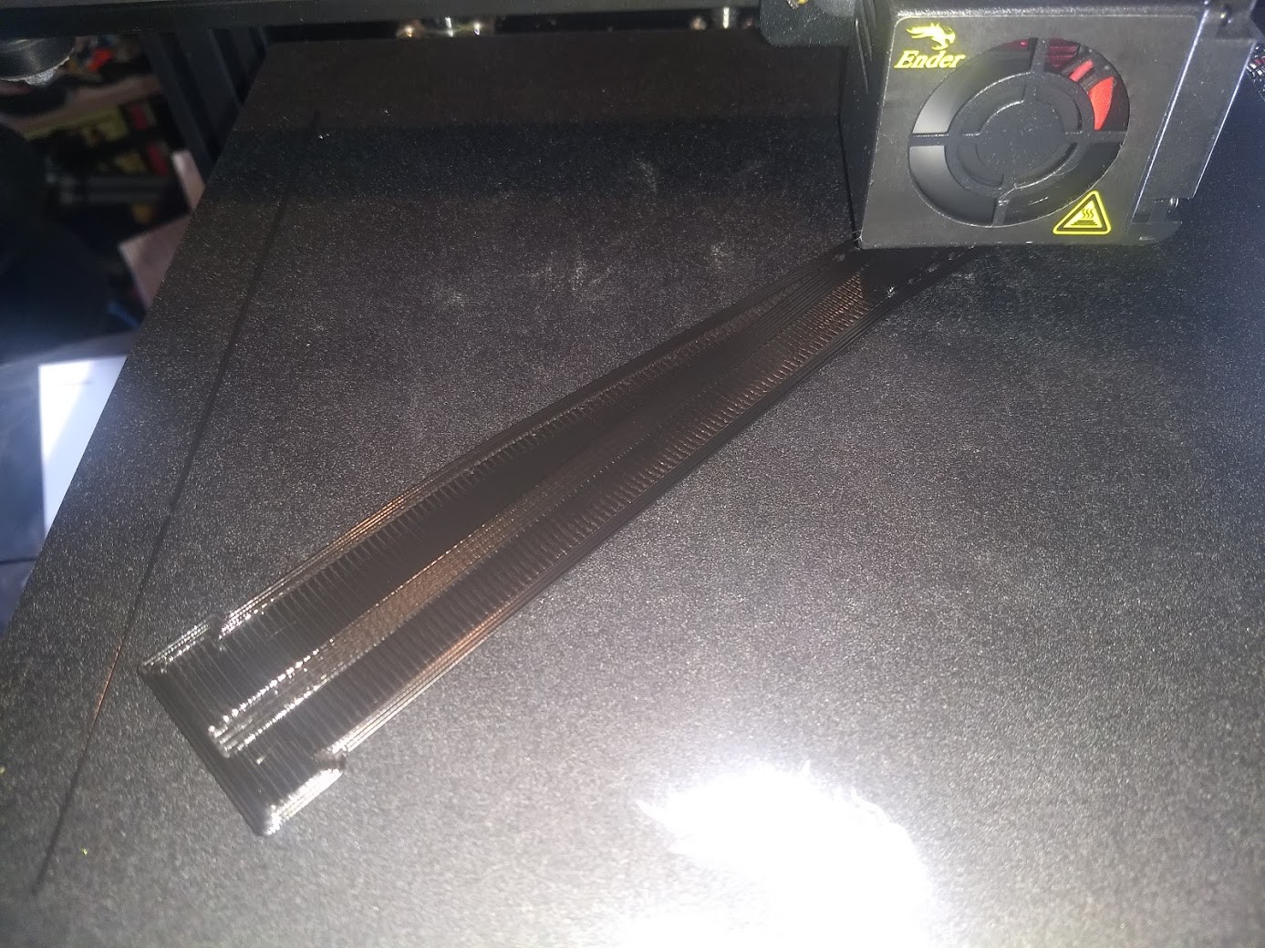
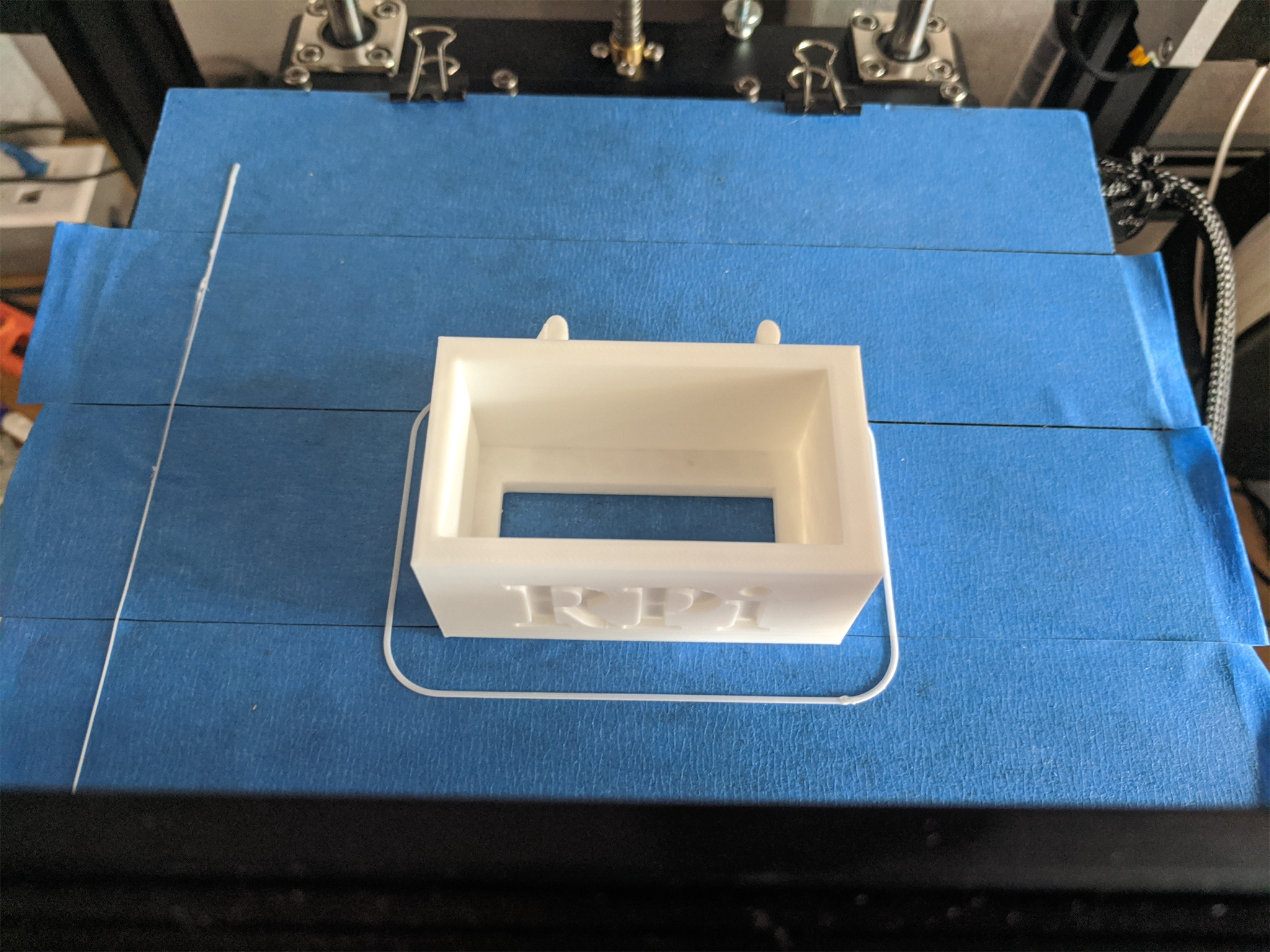
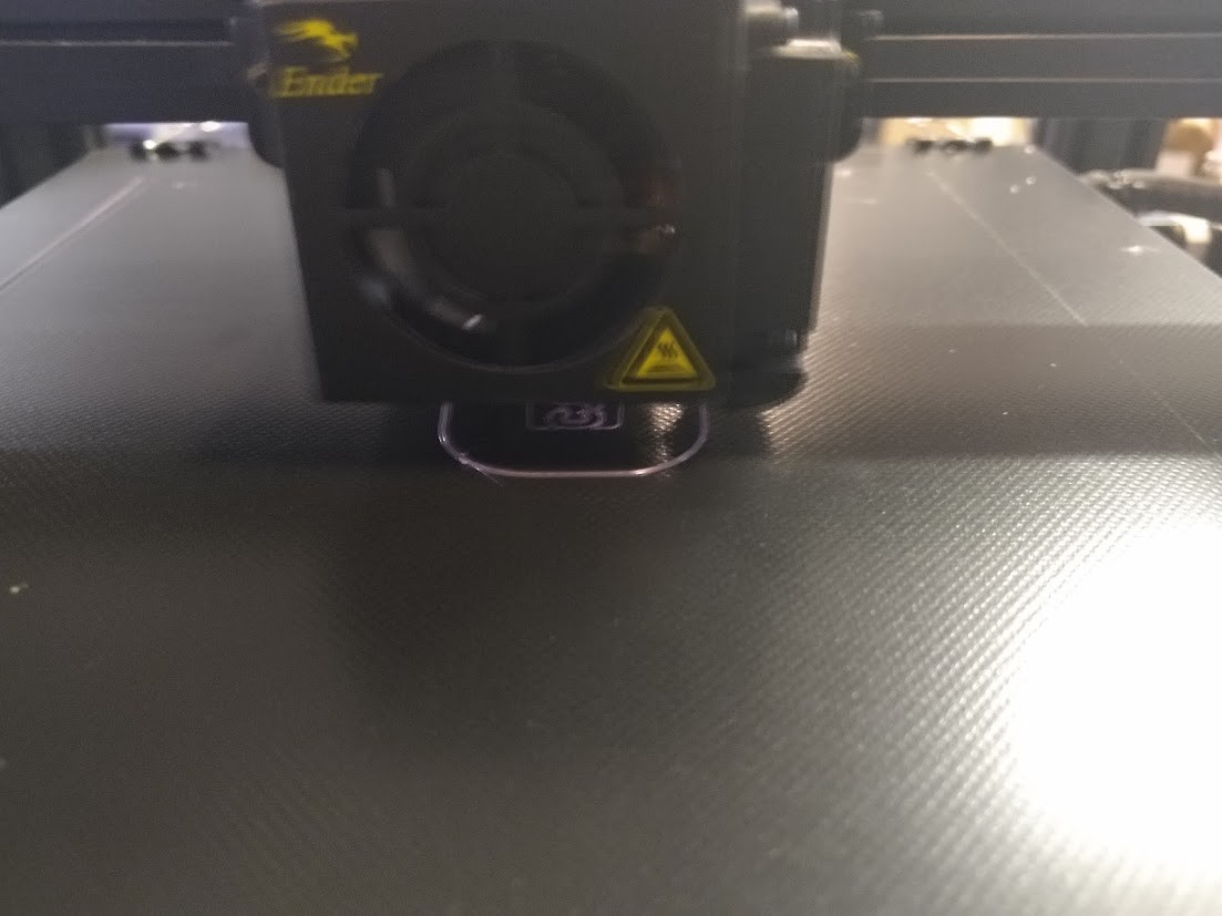
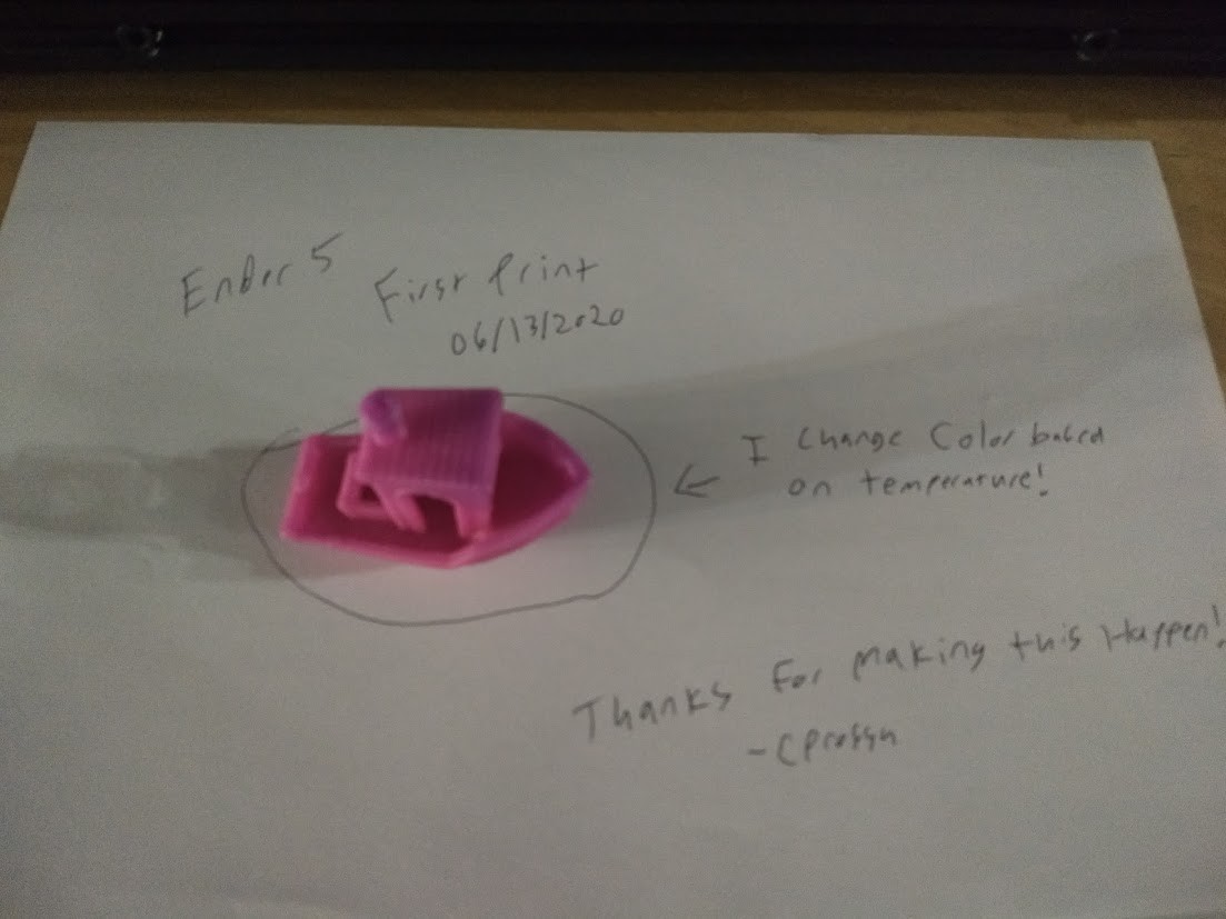
irst print with the octopi and capricorn tubing frankly looks amazing. No complaints here.
![]()
Edit 09/08/2020![]() First print done with the OctoPrint and the Capricorn tubing. Not a lot to complain about here. Also did a print without the painters tape on the other machine, and it came out great as well.
First print done with the OctoPrint and the Capricorn tubing. Not a lot to complain about here. Also did a print without the painters tape on the other machine, and it came out great as well. -
A quick extra touch 07
09/02/2020 at 21:41 • 0 commentsAfter noting some problems that could be fixed with limiting the air coming down from the heatbreak fan, and other issues that could be helped out with more even cooling, I printed blower/fan parts coolers for both printers in https://hackaday.io/project/171699-hotrod-ender-5s-for-the-hackerspace/log/183126-another-build-day-06
Again that's from https://www.thingiverse.com/thing:4262259 , and if thingiverse implodes (like it has a tendency to do), you can grab the file out of the project files on the hackaday page for these printers.
![]()
Remove the two lower allen head screws holding the blower assembly for the blower shroud, and mind the blower cover, it likes to pop off! Remove the stock blower shroud at the bottom.
![]()
Put the new blower shroud on. There's a clip on the back of the new shroud, make sure it lines up with the back end of the metal cover or it will go on uneven and you'll not be very happy needing to unbolt it again for another try!
![]()
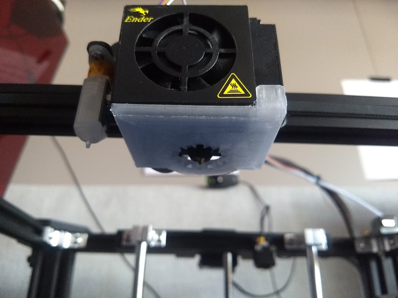
Admire your handiwork, look for any low or uneven spots, and make sure it all fits as you intend it to.
Dang that looks good!
-
Another build day 06
09/01/2020 at 16:16 • 0 commentsIt was really hot in terms of temperature at our hackerspace since our Air Conditioner basically imploded, so I did not take as many pics as I did of the first printer going together, and the ones I did take are awful in terms of quality.
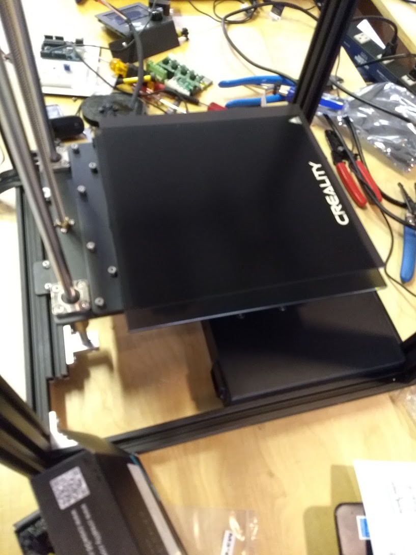
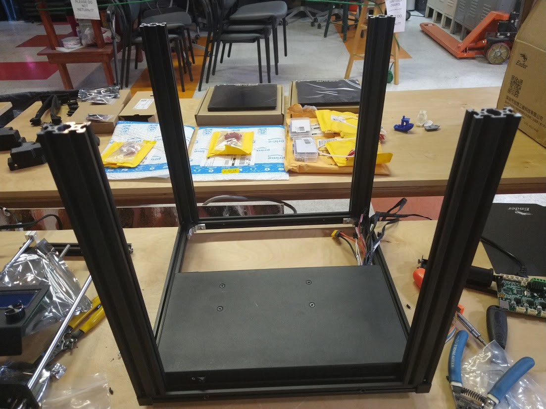
On the previous printer build I did not show how I installed the glass printer bed:
![]()
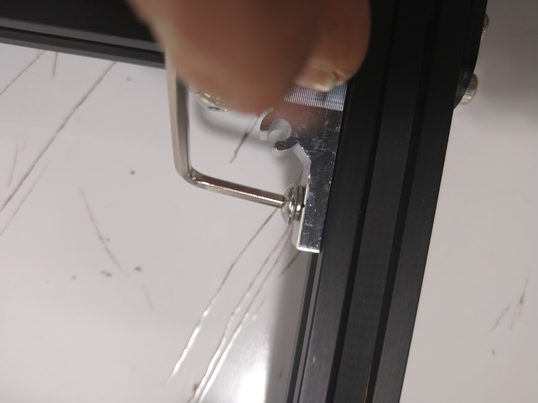
I removed the pull off magnetic bed from the top, but left the magnet surface below intact so we can use it later on if we want. I held the glass bed onto the machine using small binder clips.
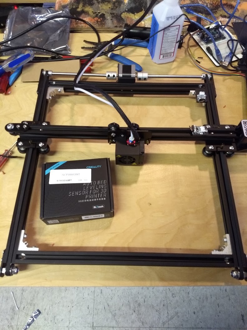
We finally got the BLTouch kits in so I figured I would go about first building it into this machine, then adding it to the existing machine after I knew what I was doing.
![]()
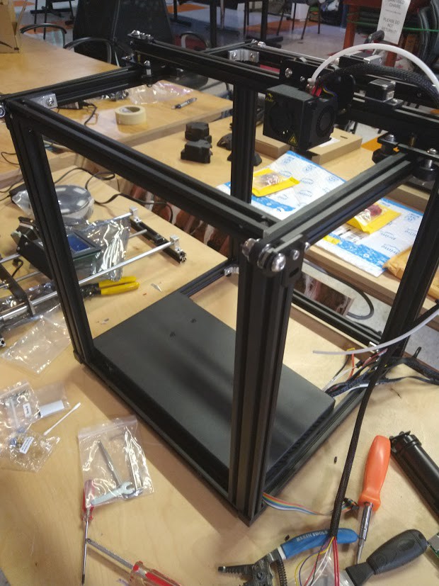
Since this printer was still being built, I decided here to take everything apart and see what I would need to do.
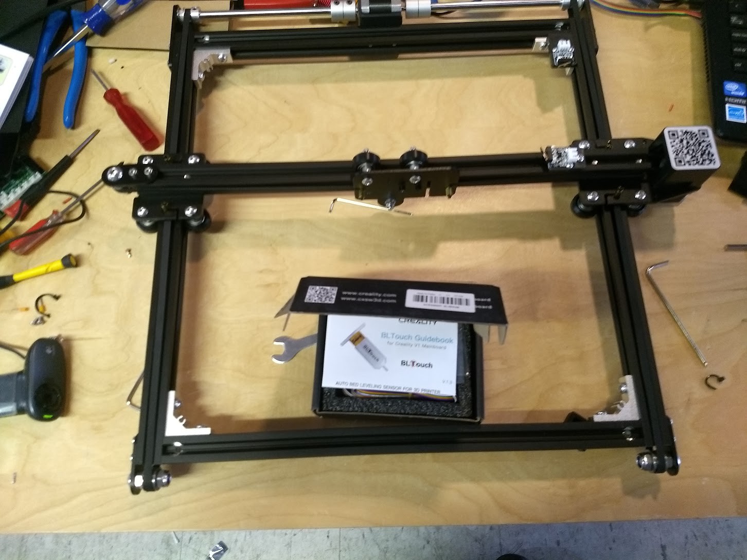
![]()
One of the nice things about the Ender 5 is how serviceable and easy to get to everything is compared to quite a few other designs of printer. This makes modification a bit easier, and if you are careful you can make sure that mods you do don't interfere with other mods, or make the printer harder to service.
![]()
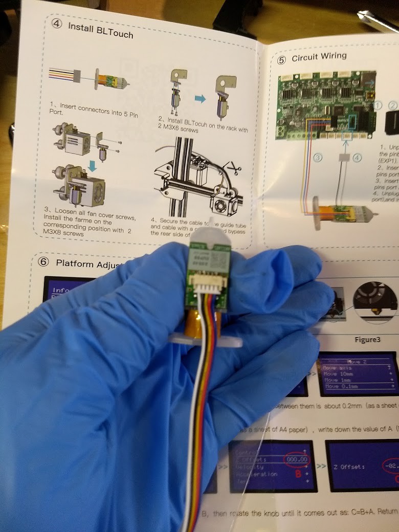
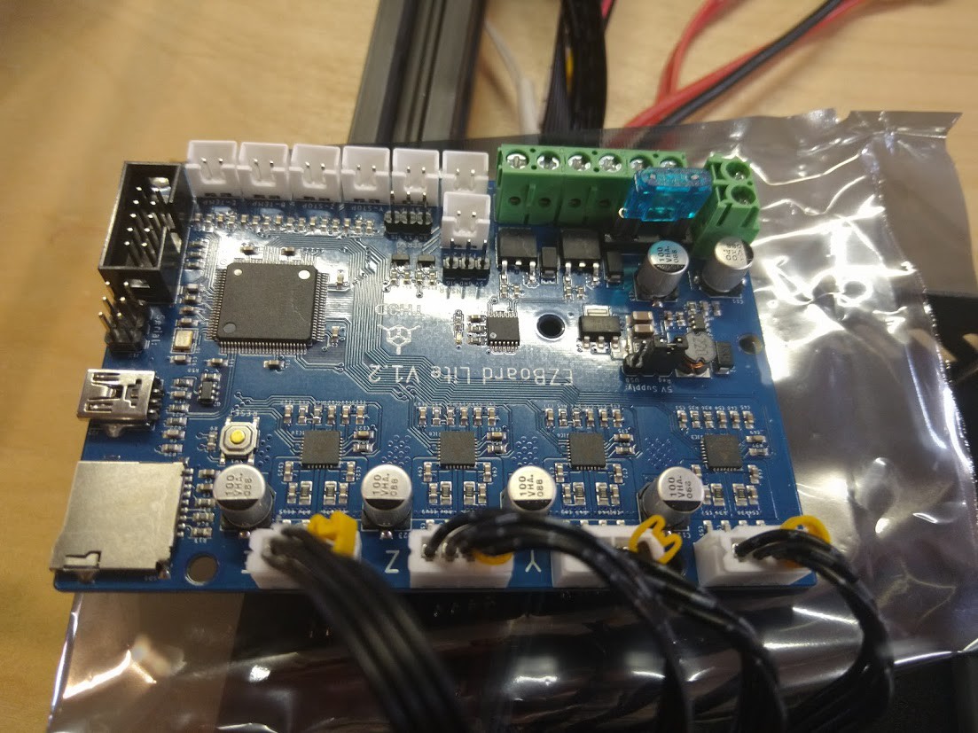
I was hoping to find a good pinout in the manual for installing this thing, but what I found instead was generalizations. This is China so I know from experience that nothing, especially pinouts, wire color, and polarity, is a given. If I don't want to blow this thing up, I must take my time here, especially since I am using a third party controller board and not their own.
![]()
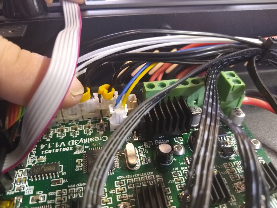
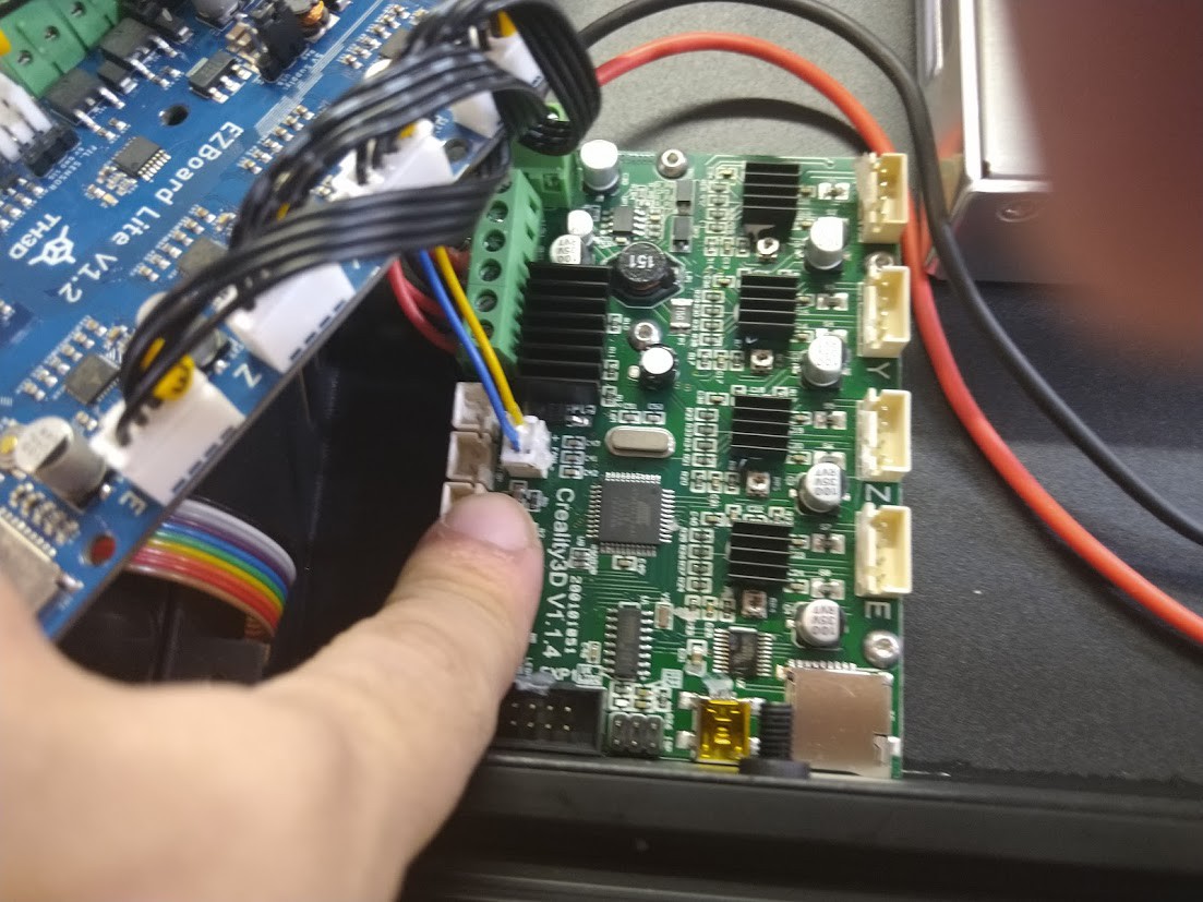
So we need to do a little research now,. The White and Black wires connect to where the limit switch would go, and that seems normal. What is puzzling now is looking at the colors Blue, Red, and Yellow. When I look at the documentation for the EZBoard Lite V1.2, and other BLTouch sensors, the common color coding seems to be Brown, Red, and Yellow.
![]()
Well at least it's "close", but "close" and "correct" are two different things when you are trying to keep the magic smoke inside of a device.
![]()
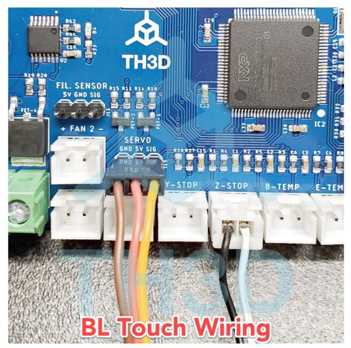
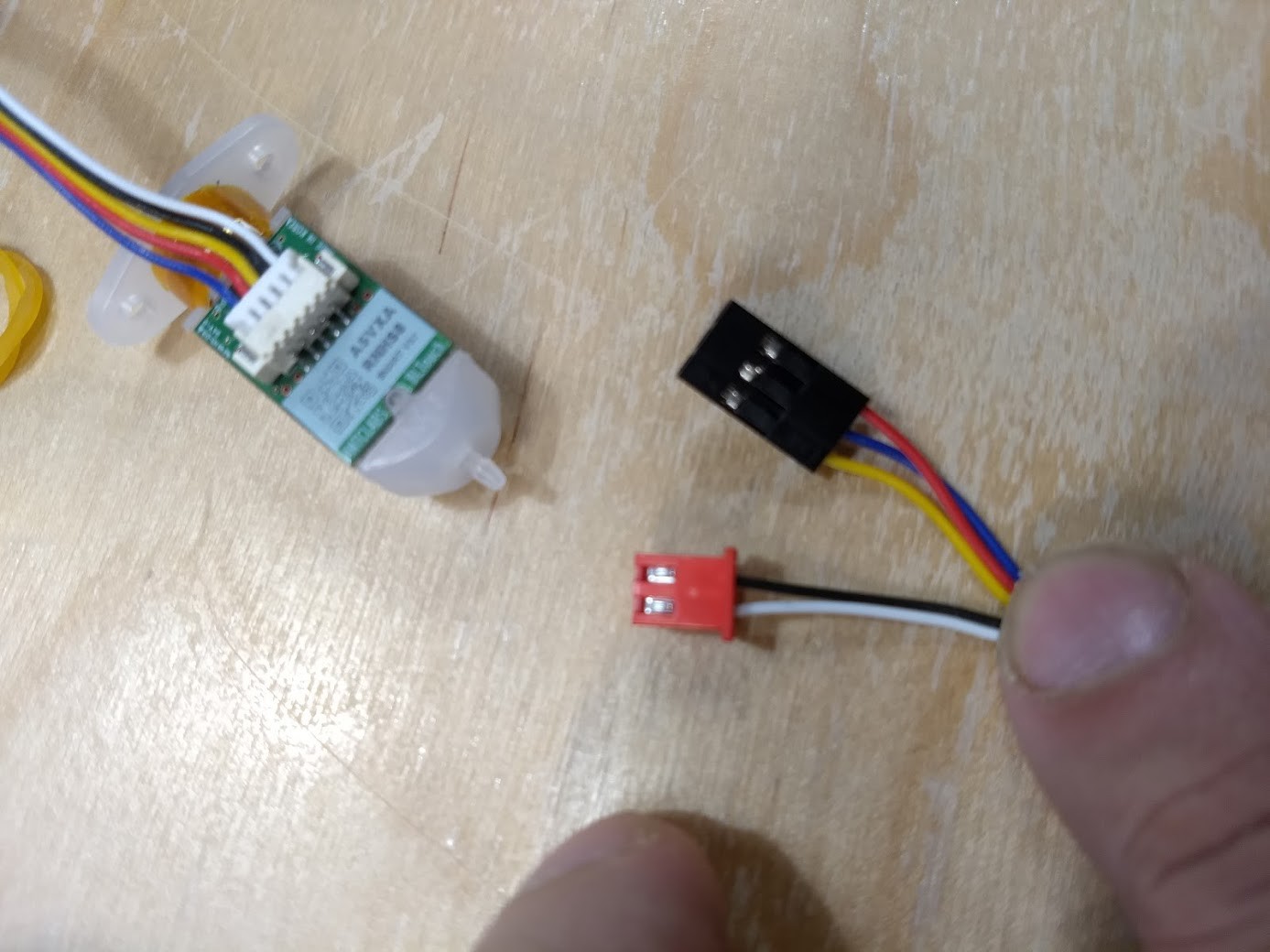
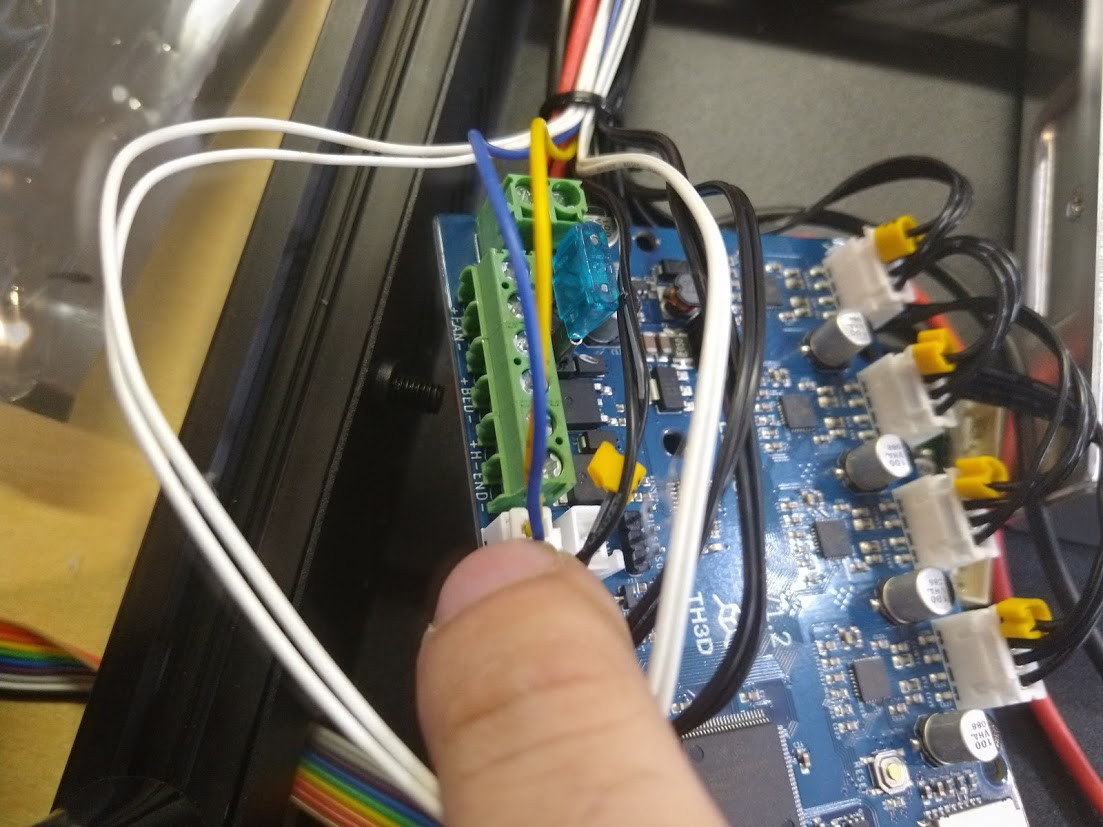
So our TH3D documentation expects Ground on the brown wire, 5 Volts on the red wire, and the Signal coming on the Yellow Wire. Looking at our stock BL Touch sensor image from the internet, we see that our wiring harness matches up except for the wire in the brown position being blue. No sweat, let's look at the connector we're to plug into the control board next.
![]()
WHOAAAA THERE! That's not going to work at all. Our control board would be sending 5 volts right down the ground, and the 5 volt wire would be grounded. In other words the polarity would be reversed! I understand some newer versions of these sensors are not supposed to blow up if they are hooked up wrong, but let's not test that today!
![]()
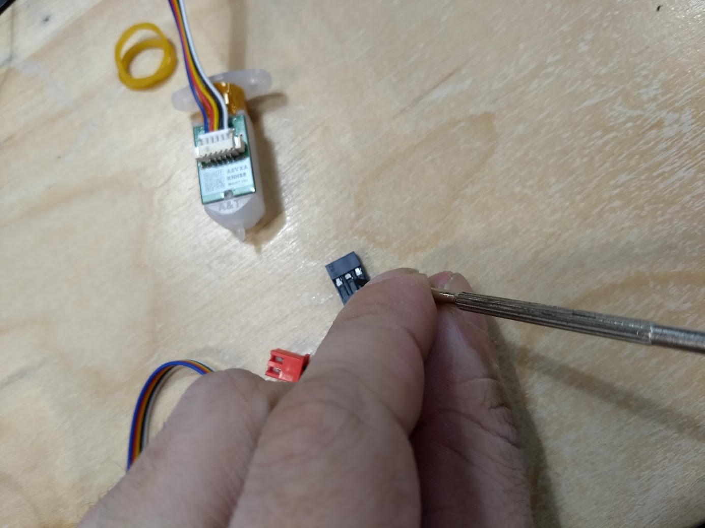
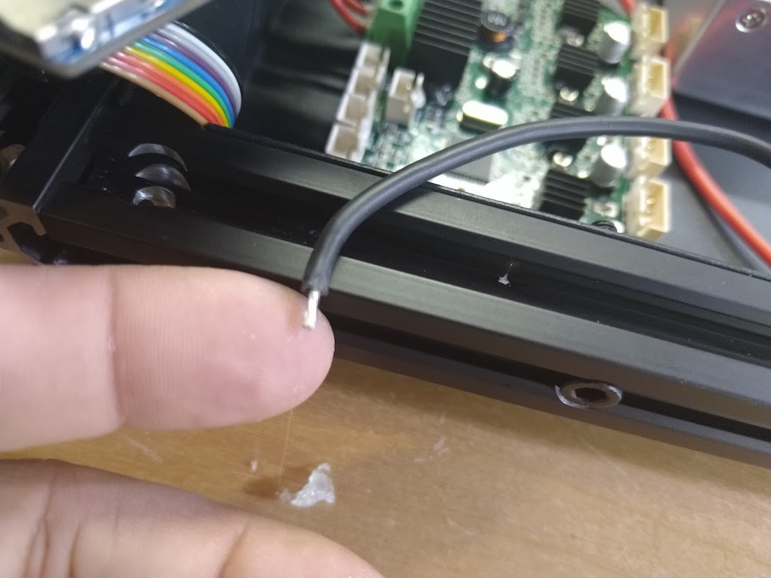
We're going to do this the wrong way and use a jewler's flathead screwdriver to extract the terminals we need to swap out from the housing by carefully and not breaking the plastic housing, or the tab holding each terminal in place.
![]()
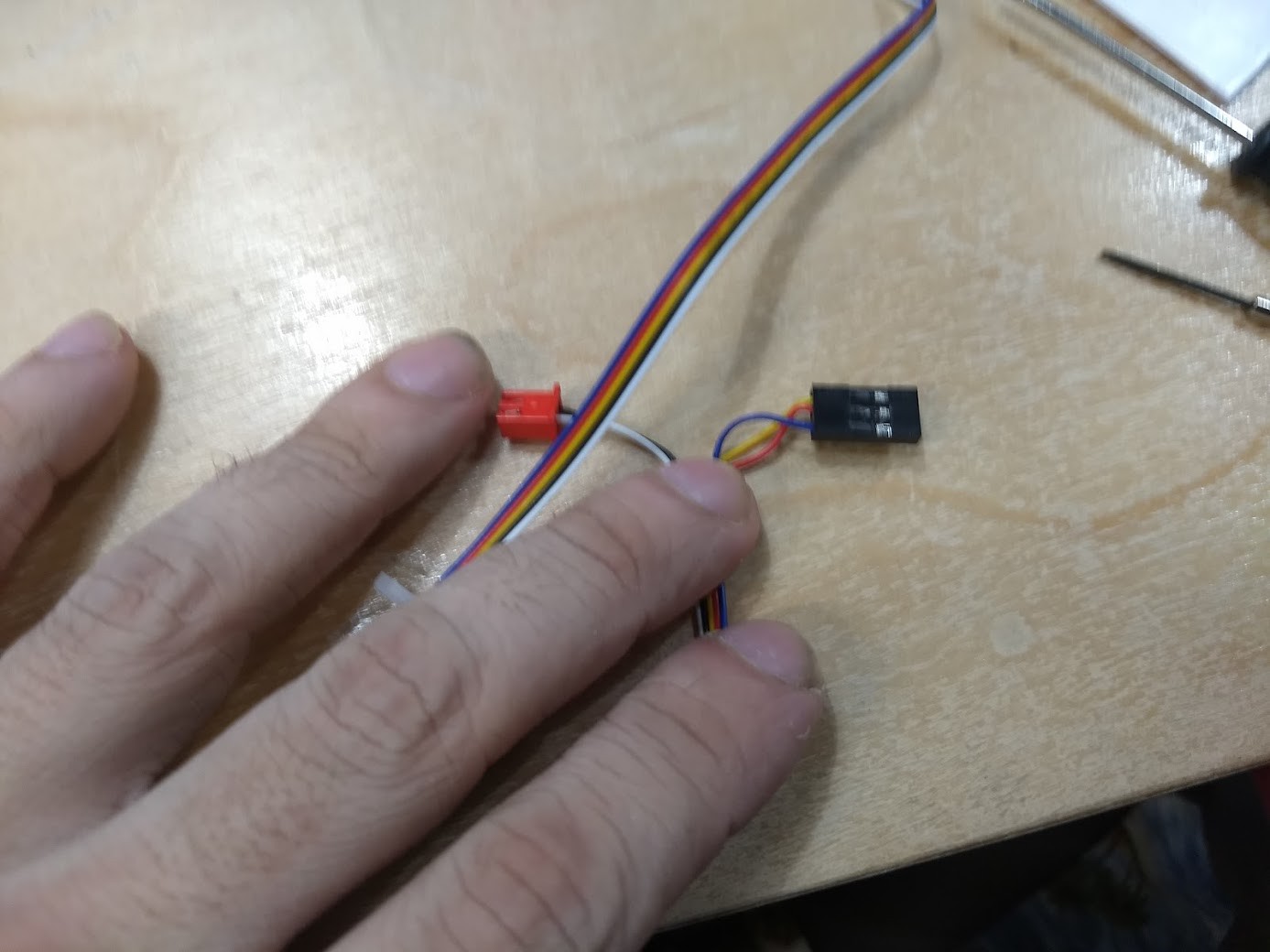
Good enough. I better make a note of this here:
If you are from Heatsync Labs looking at this post in the future and are installing the stock Creality V1.1.4 Board for some reason, do NOT INSTALL the BLTouch without swapping around the polarity on the connector!
(Also reminder to self: Add that note to the place the stock board is placed in so this doesn't happen, maybe even wrap the old control board with the note so they have to take the note off before getting to the old stock board)
I really would prefer it if I could install the BLTouch in such a way as you could remove the fan shroud/hotend without removing the BLTouch, however that's not the way this kit is set up. Perhaps that will be a thought for future builds. At least the bracket is metal, and it is pretty easy to take on/off. They do give you longer screws to hold both the bracket and the fan shroud in, so I suggest using them.
![]() I managed not to take any pictures of using Velcro and Zip Ties to affix the BLTouch wiring to the rest of the printer. I then made a quick test print to make sure everything was in order before hooking the wiring of the BLTouch to the controller board, and everything seemed to be in order.
I managed not to take any pictures of using Velcro and Zip Ties to affix the BLTouch wiring to the rest of the printer. I then made a quick test print to make sure everything was in order before hooking the wiring of the BLTouch to the controller board, and everything seemed to be in order.![]()
After I tried BLTouch for the first time, I was sold, so I spent extra time, fitted it to the other printer, and built a firmware up using the TH3D site just adding in the BLTouch support. Everything worked as it should, and now we have two 3D printers that offer identical results.
![]()
![]()
Really I can't be happier with the progress. Next up is figuring out what slicer settings are the best for the materials we have on hand, setting up the Raspberry Pi's with Otoprint, a camera, and maybe a touchscreen, possibly cutting some acrylic panels out to help with ABS work, and fitting a fan shroud to each machine to help with materials that do not enjoy the extra cooling the heatbreak fan gives them.
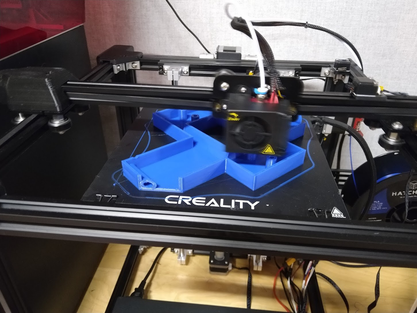
The shroud I found is a 2 part design (You glue the lower half to the upper half) and it bolts up where the stock blower shroud goes. I found it at https://www.thingiverse.com/thing:4262259![]()
Time will tell if printing these out of PETG was a good idea. I like the two part print, as it lets me make sure the final part is of high quality and without stringing/defects that could impede the performance of the part.
I think that brings this posting up to date! Two working 3D printers, both configured the same, and all that is needed now is some tweaking and an octoprint setup to finalize them.
Edit:
![]()
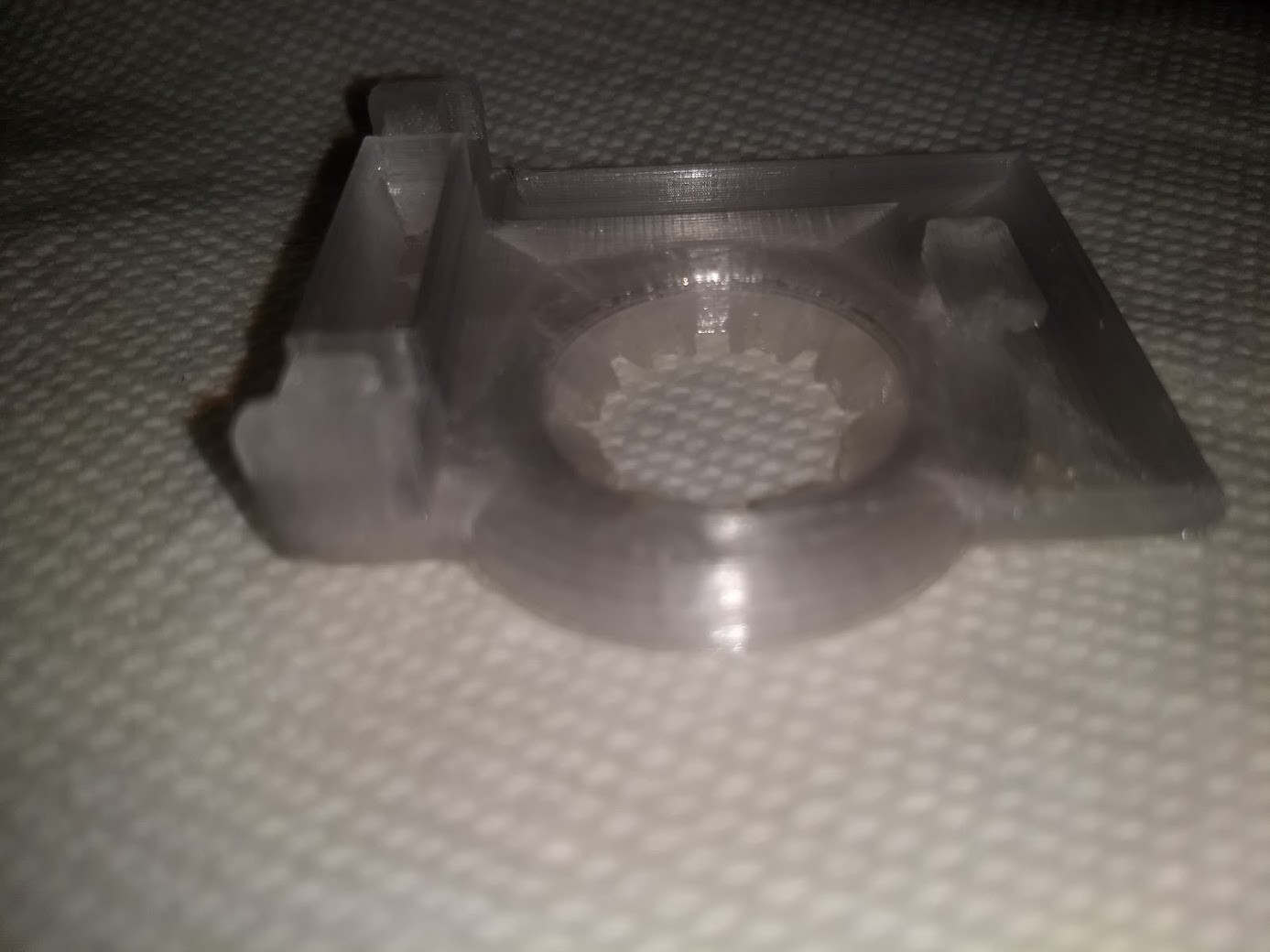
Here are the two parts of the blower shroud.
![]()
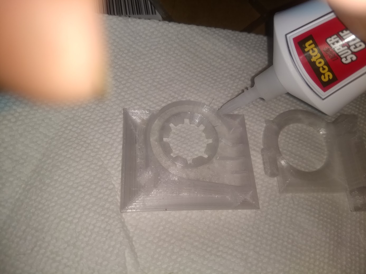
Add in some superglue on one of the mating surfaces...
![]()
Firm pressure on it for a minute or so...
![]()
And done! Will make another one and install them on the lab printers next time I am in.
-
Tweaking and waiting for parts 05
07/19/2020 at 16:15 • 0 commentsWe have been using the first Ender 5 we built for a while now and I got to the lab to finally able to tweak some things that needed doing.. I've decided I will better document the procedures when I build the second printer up.
1.) The firmware I built from the TH3D site did not have stealthchop enabled on the Extruder stepper motor, so it was noisy. I have enabled stealthchop for the extruder stepper motor via the advanced configuration menu inside of marlin menu on the printer itselt, and it's all good now.
2.) The squeaking of the Z axis drive was solved by removing the Z axis leadscrew, cleaning the grease off of it and the brass leadscrew nut with isopropyl alcohol, flipping the leadscrew upside down from the as installed position, and lubricating it with Zoom Spout oil.
![]()
I am happy with the results we've been getting so far. Although I was intending to shim the bed, it may not be needed afterall. The printer is being put through it's paces, and the second printer that was missing finally got delivered. We are still waiting on the BLTouch kits. They have now been shipped, however they have arrived in the states.
I have decided I will build the second printer with the BLTouch kit and also document the steps I missed when building the first machine. I'm set on finding any issues with the bed leveler, and also learning how to use it, before I modify the first printer.
Other than that, both machines will likely get wiring dress with some clear spiral wrap similar to how I have my own Ender 5 at home set up. I'm not yet sure how I want to try and make the wiring easy to get to if it comes time to replace the hotend or either of the fans, however I want this to be an easy task when the time comes. Just as my own ender 5 at home, the v-groove delrin/plastic bearings do collect dust, and I am trying to decide if a little felt/brush wipe might be in order, or just to have one near the machine for people to manually clean/dust the bearings. I'm thinking we should also get a pack or two of them since they are cheap enough to have laying around as spare parts just in case. Each machine uses 11 of the things. (They can be source on Amazon for around $1 each in packs of pretty much whatever you want, buyer beware though, read the reviews, some are correctly sized, some are not!)
-
Build day 04
06/20/2020 at 01:02 • 3 commentsAll things do not go as planned. One of our printers does not seemed to have shipped, or got lost along the way, and both of our BL Touch kits were missing in action, and contrary to the initial order in fact backordered until who knows when. Raspberry Pi 3B's are still nowhere to be found, however at least it looks like there's been a lot of movement on the Raspberry Pi 4 boards and octoprint, so that may very well be the way we go.
So the first build day was here and has passed, I officially did it back on 06/13/2020. Not everything I want is installed on the printer, however it is functional, so I will take you on a journey of checking out what we have and building the unit we did get in up.
![]()
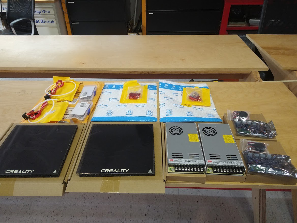
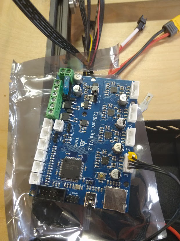
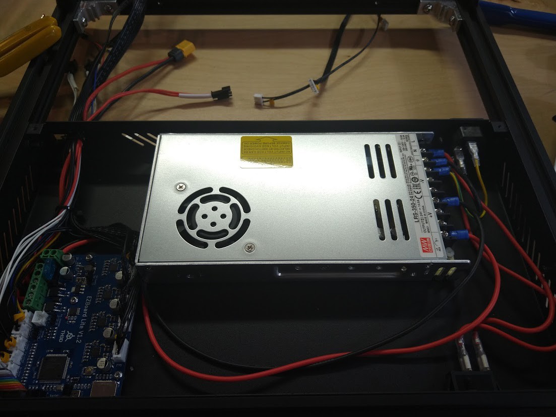
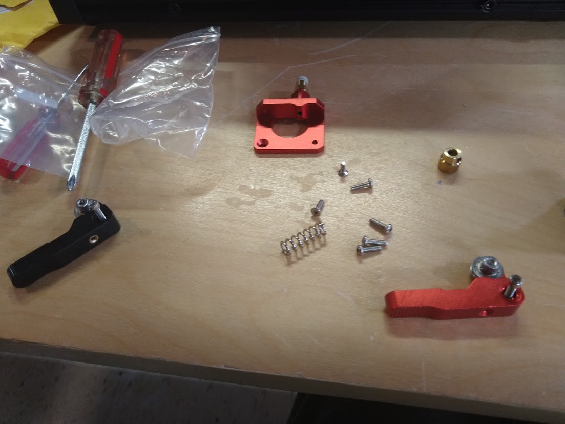
So in this picture, starting from the upper left, we have our two extra entire stock Ender 5 extruder assemblies, 2 "T-Nut" kits that were recommended, and two aluminum "geared extruder feeder" upgrade parts. Going from the bottom left there are two tempered glass Creality branded printer beds, two Meanwell 24V-350Watt power supplies (Model LRS-350-24), two TH3D EZBoard Lite V1.2 control boards, and two TH3D filament sensors which are supported natively by the EZBoard control boards. No Ender 5 BLTouch bed leveling kits to be found.
![]()
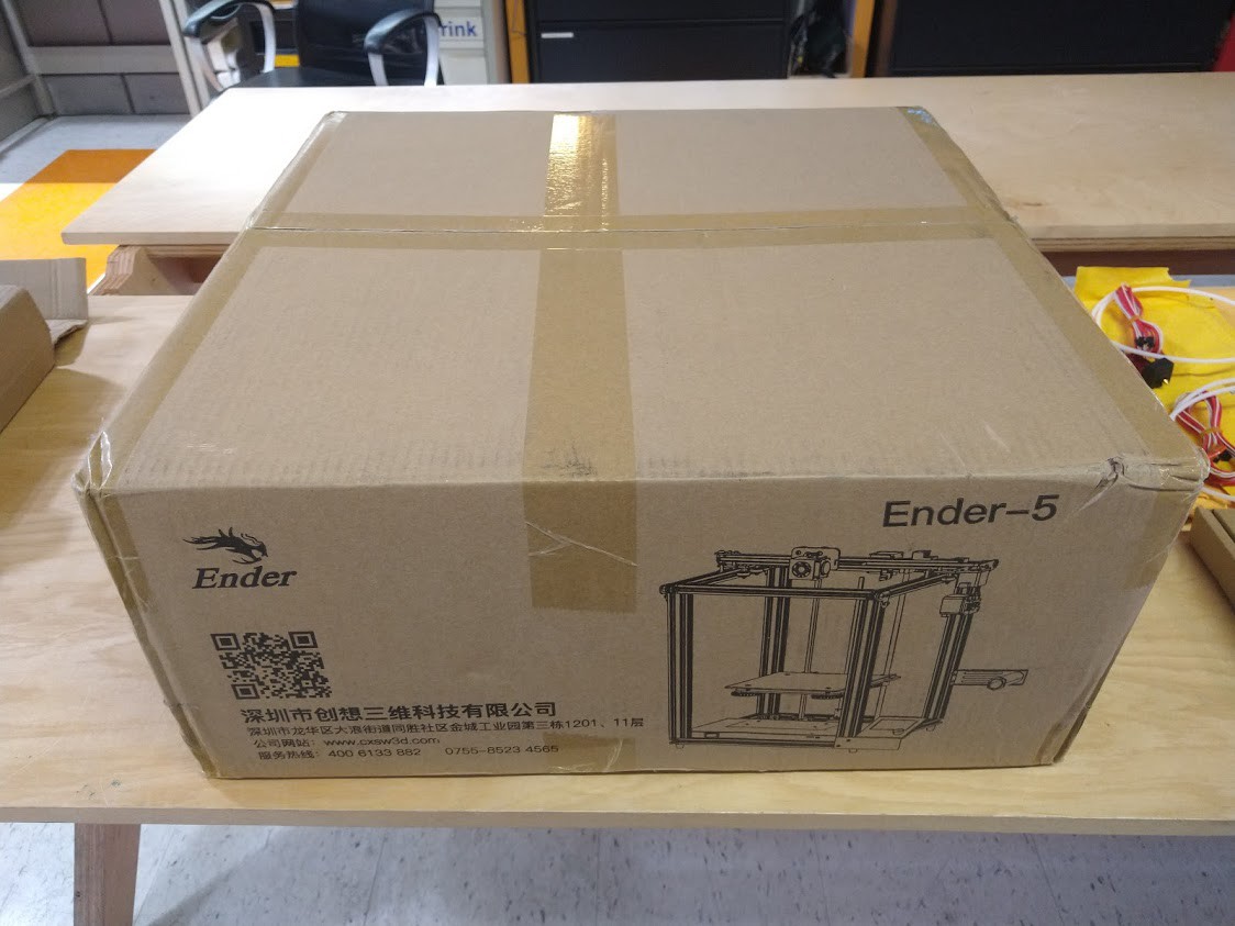
In this picture you can see we only got one of our two promised Ender 5 3D printers. We shall build this one up and use it as an opportunity when the second one comes in to document anything I forgot to on this machine. (Well other than the BLTouch kit that is). I already checked that there were not in fact 2 printers occupying the same dimensional space through a quirk of quantum physics, sadly.
![]()
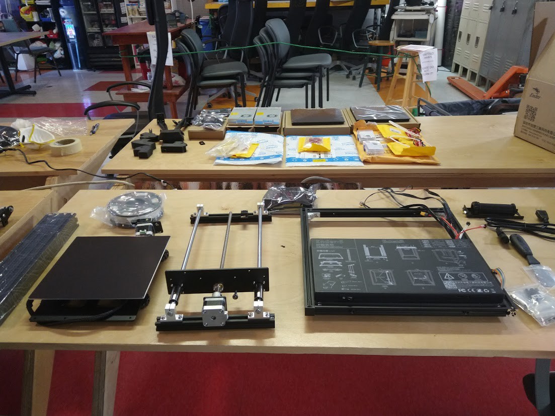
Now to make sure we have enough pieces and parts to build a printer out of, time to spread it out and make sure it's all here. Going from Left to Right, Up to Down on the table closest to us, We've got 4 double wide aluminum '2020' extrusions that will be the support structure for the top of the machine, we have a roll of filament kindly provided for testing, the stock Ender 5 display screen (in a mylar bag), the extruder feeder assembly, the heated printbed, the Z Axis assembly (which includes motor, bearing assemblies, lead screw, mounting hardware, and aluminum '2020' extrusions, the base of the machine (which includes the stock power supply, stock control board, a case covering both, wiring, aluminum extrusions, and various pieces of mounting hardware and triangle brackets. They've also been kind enough to supply a assembly for hanging a roll of filament off the side of the printer, a power cord, a scraper, and a bag of machine screws and tools for the printer.
![]()
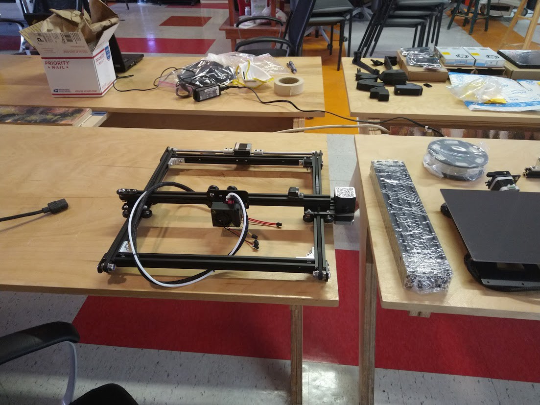
Here is our X and Y Axis gantry crane (which contains the entire extruder assembly (PTFE tube, wiring, heater block, heater cartridge, thermistor, a fan, a blower, a heatbreak, nozzle, nozzle cover, and a dandy metal shroud to keep it all contained), the X axis motor, the Y axis motor, bearings and belts all over the place ready to drive both, aluminum '2020' extrusions and triangle brackets to hold it all together. This part goes on the top!
![]()
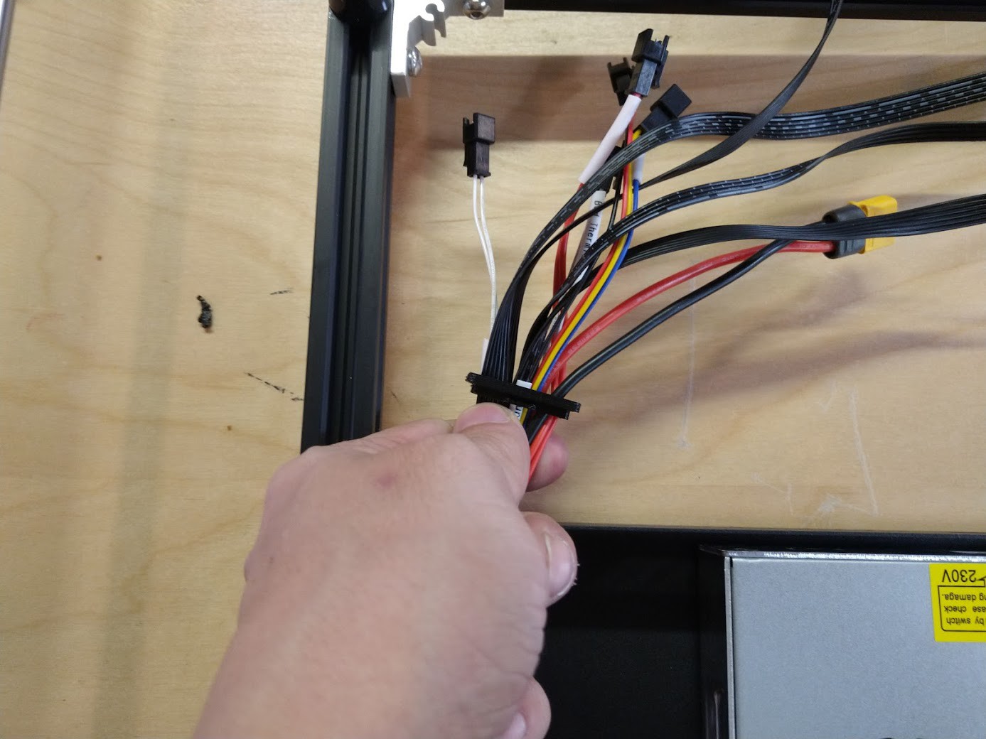
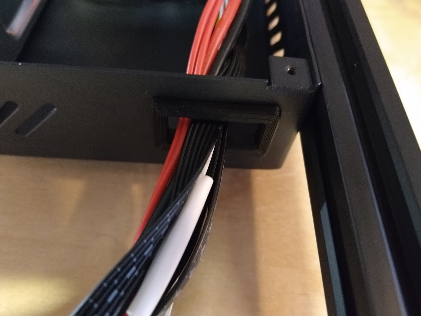
This is a great time to feed all of our wiring through the snap in cable protector we printed up earlier for this very reason.
![]()
It snaps in place, showing us that we did good. Now the sharp edges of this metal casing will not wear through the control wires of the machine. This is a very good thing.
![]()
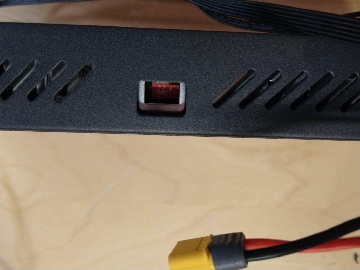
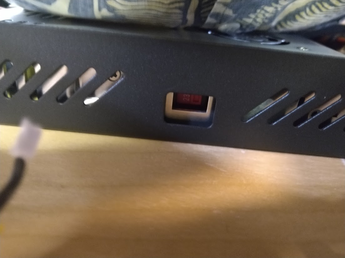
While we're down here, let's change the voltage of the stock power supply to match what we get in USA voltage electron magic pixies out of our standard outlets.
![]()
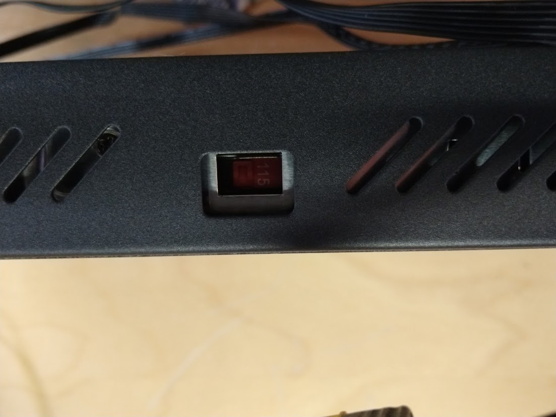
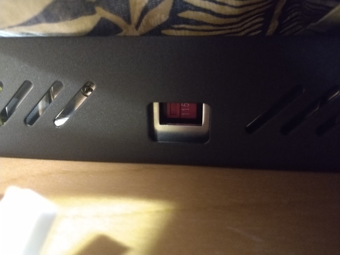
Much better. Even though we don't plan on using this power supply, we want to make sure it's ready to go in case we press it into action later. Speaking of that power supply, we need to get this thing out of there!
![]()
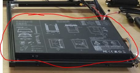
Just so you know, the really nifty top part of the control box with the awesome assembly instructions is hiding the screws for the power supply. Not cool!
![]()
Wow, that is a lot of adhesive, took a lot of patience to get off without ruining it. My placement of this giant sticker actually created several moments of hijinks when I placed it out of the way, for possibly refitment later. I myself managed to get my gloves, my cell phone, a part of the printer, and a mylar bag stuck to it, right before my colleague got their journal stuck to the darn thing. I have decided this thing will go away, and perhaps we'll make some custom graphics for it after it's proven itself, ones that do NOT cover the power supply screws!
![]()
Well that's ugly...
![]()
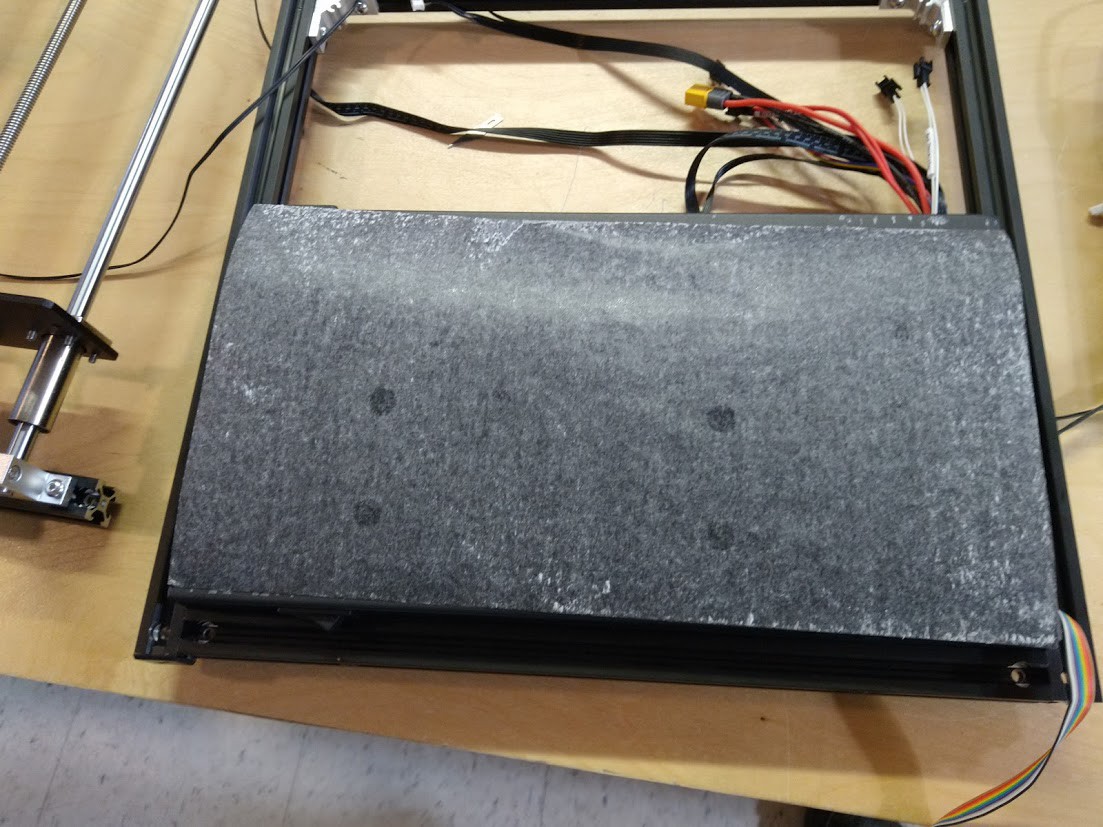
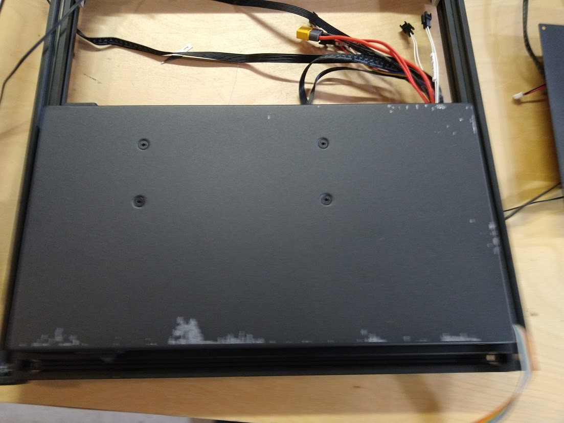
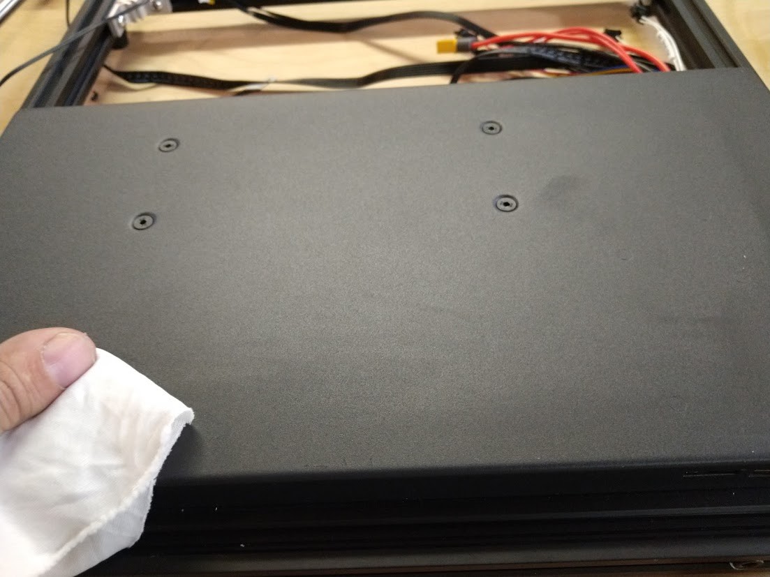
Nothing a little 90% isopropyl alcohol, elbow grease, and a rag could not fix at least.
![]()
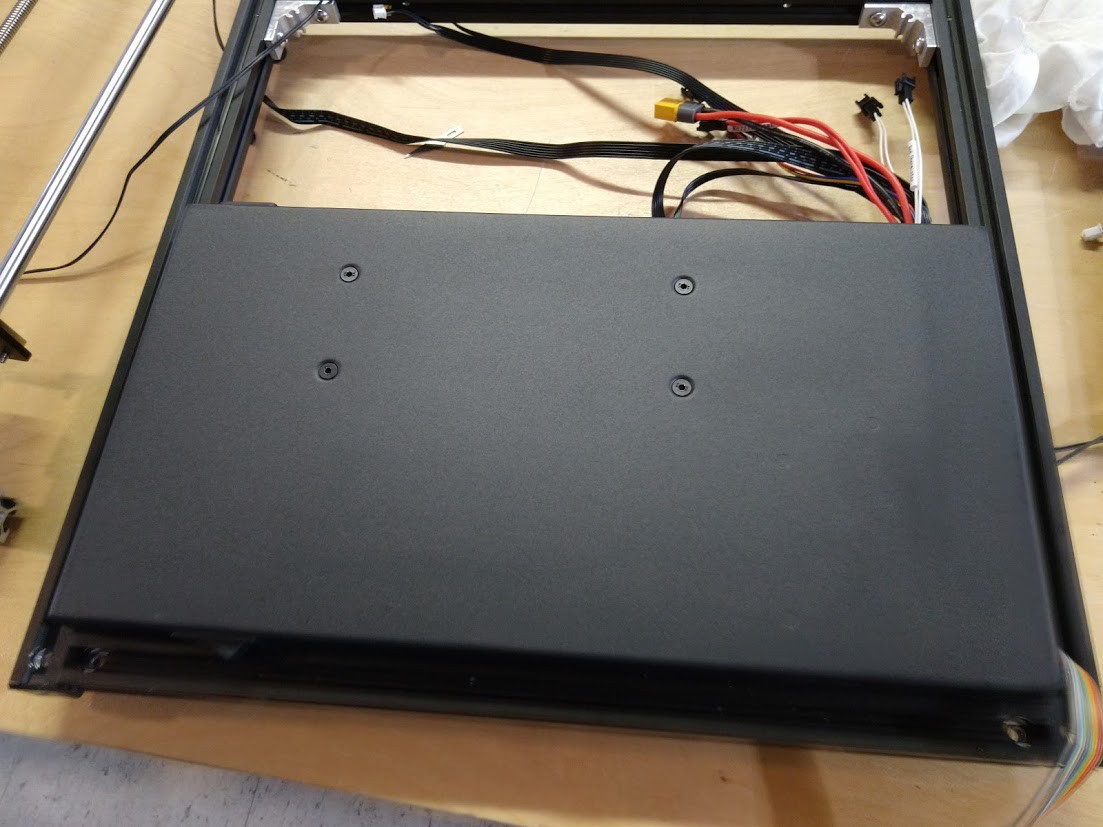
A clean slate.
![]()
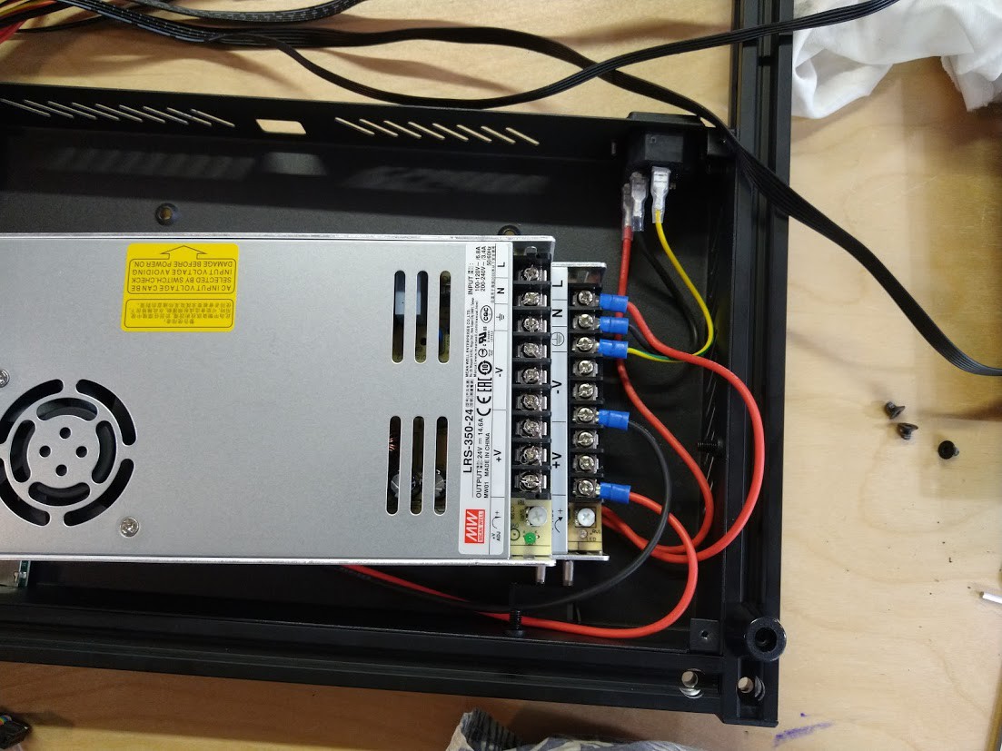
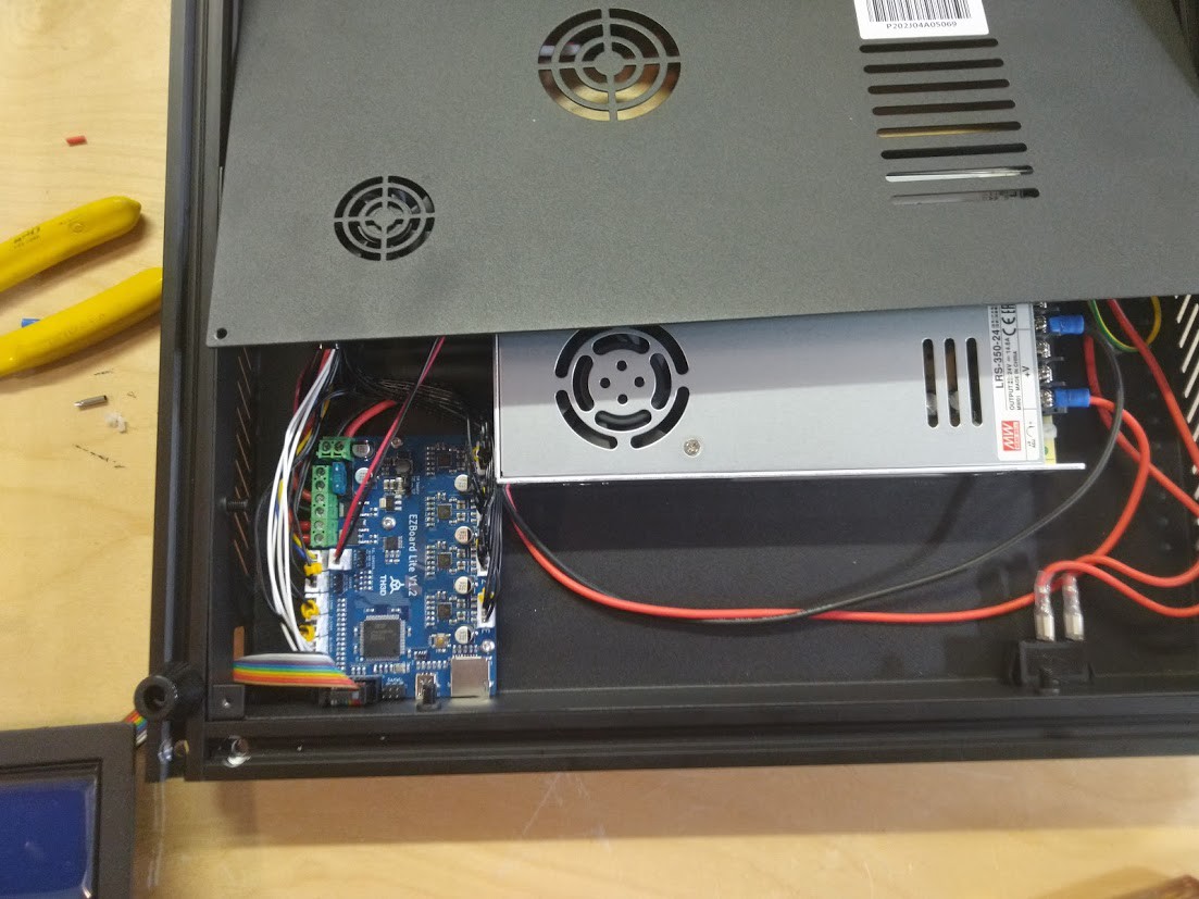
We took the bottom off of the chamber which holds the Power Supply and the Control Board. I am comparing all the connections on the cheap chinese ripoff power supply that came with the printer to our Meanwell unit to make sure they are the same. Looks good.
![]()
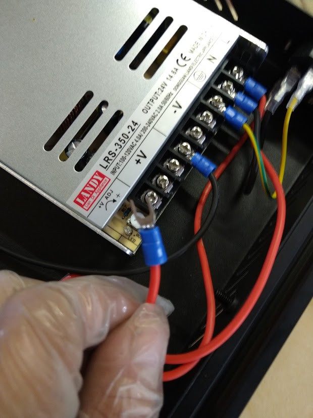
I decided to inspect each crimp connection, making sure nothing was loose or could be wiggled. I was very tempted to go through and replace all of these with known sourced 3M crimps, however these seem like they are of good quality.
![]()
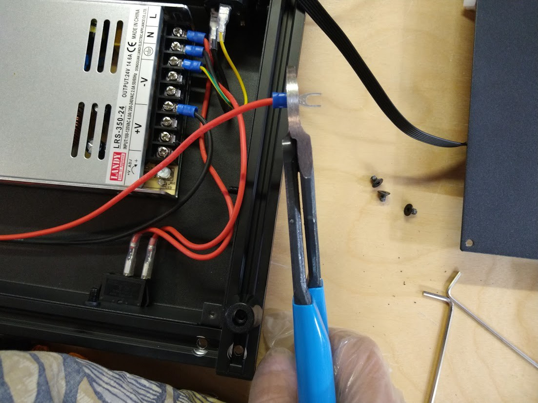
I decided to err on the side of caution, I gave each connector a little time with my hand crimping tool in the insulated crimp position.
![]()
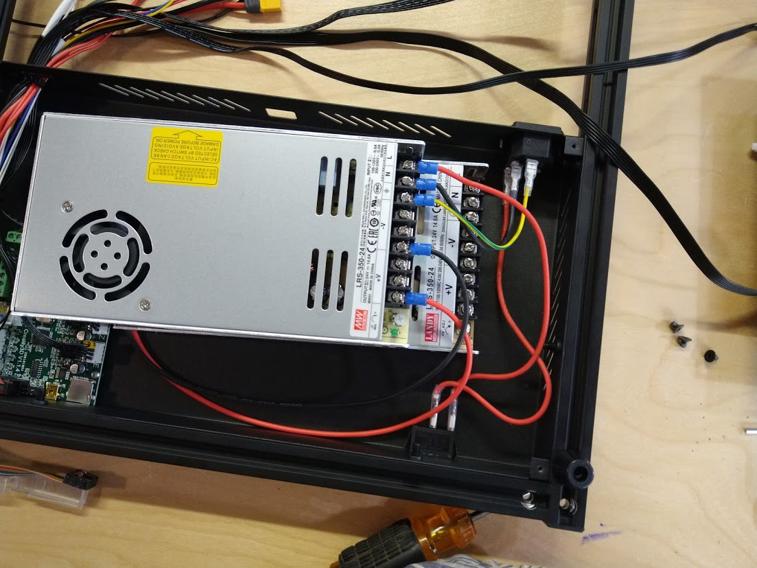
Rinse and repeat for all the remaining connections. Hey past you, it would be a great idea to set the voltage switch on the new power supply to 120 right now before you get distracted by the old control board, and before you install it the power supply screws! Wow, past me is really dense and does not listen (At least he figured it out before plugging it in, and the switch is in the same place as the old power supply, and it would have been a bigger issue in a country that uses 230v if it was set to 115v).
![]()
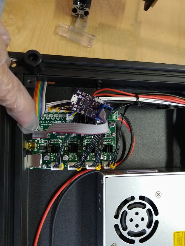
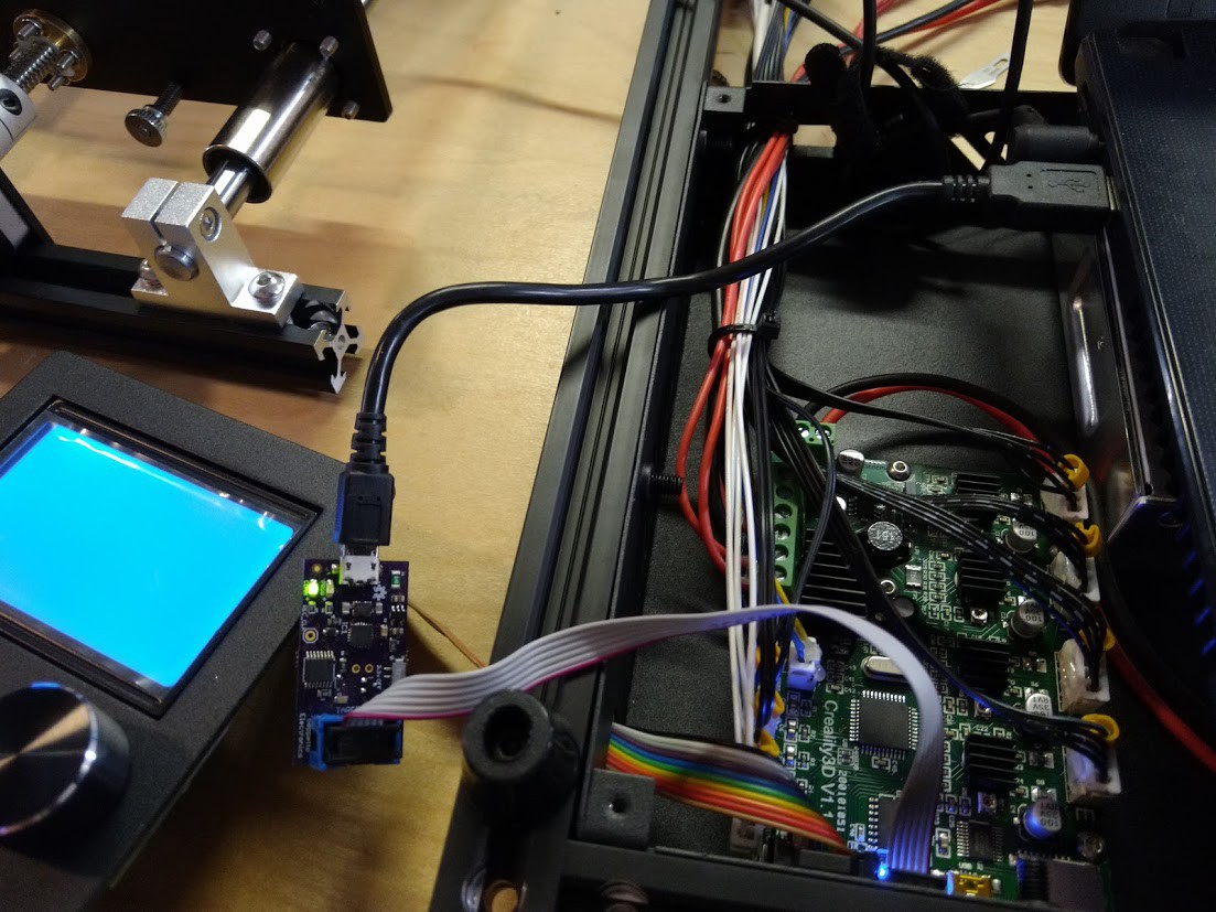
So here's the stock Creality3D V1.1.4 control board that we are going to remove and replace with the EZBoard Lite V1.2, however we still want it to be usable as a spare, and we sure don't want firmware that is questionable on this thing. This means we've got to burn a bootloader to it so we can put whatever 31 flavors of Marlin we want on it. I am going to use USB µISP I scored with my 2019 Hackaday Supercon swag bag to burn the bootloader on the stock Ender 5 board (Thanks Tindie, thanks https://hackaday.io/nsayer ! this thing has been useful on more than one occasion!)
I should note, to get it to fit the board without removing the screen connector, you do have to snip one side of the connector down on one side with a pair of sharp cutters. Not a big issue. You can also use a arduino uno to burn the bootloader too. I might demonstrate that when I build the second printer.
![]()
Hooking up our screen temporarily.
![]()
I've plugged a USB cable into the printer on the mini USB port.
![]()
Zoomed out so you can see and taste the jank. Don't let anything short out now, you hear?
![]()
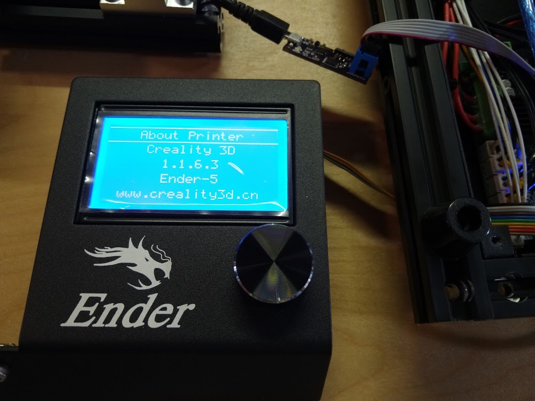
Here's the firmware my printer came with. It will never see a print from us, for we are going to cast it into exile with our programmer.
![]()
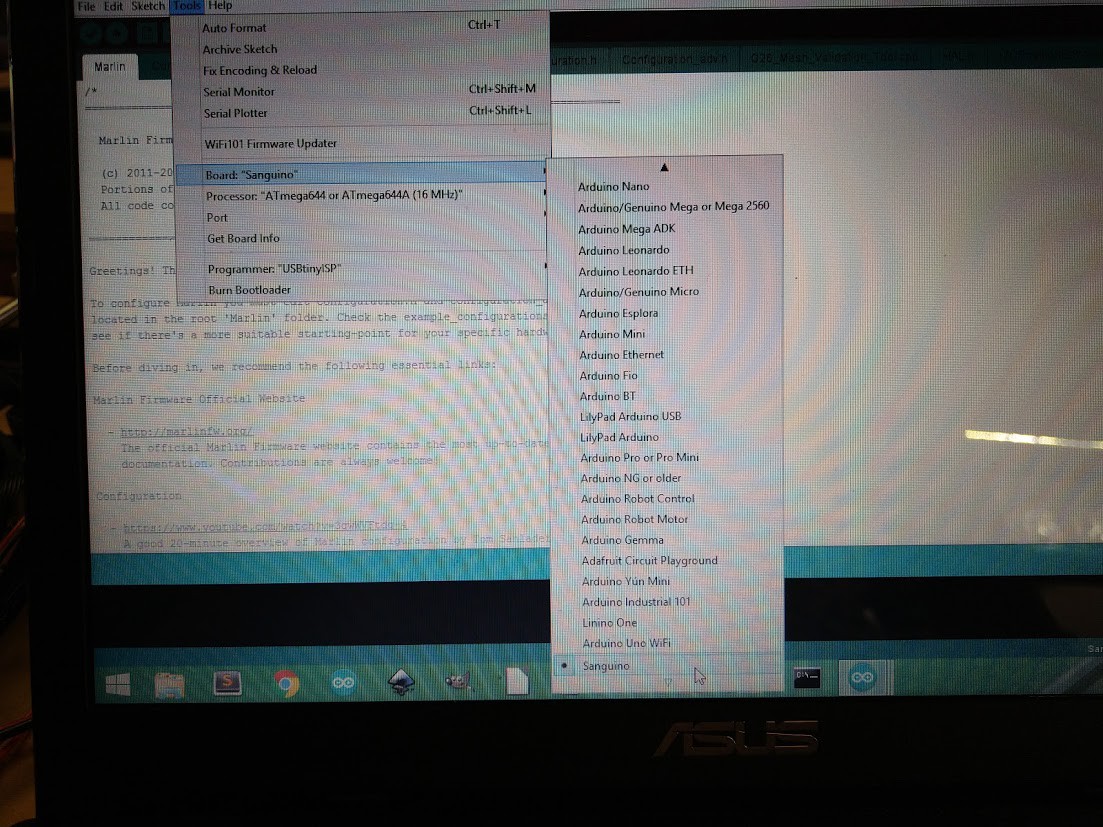
You'll want to import settings for the "Sanguino" using the Arduino IDE, then select it as your board.
![]()
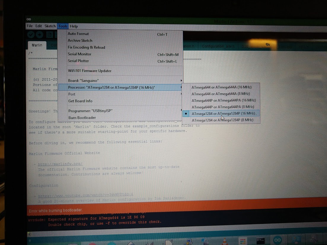
Make sure the processor is set as ATmega1284 or ATmega1284P (16MHZ)
![]()
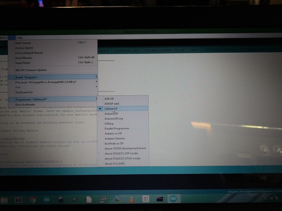
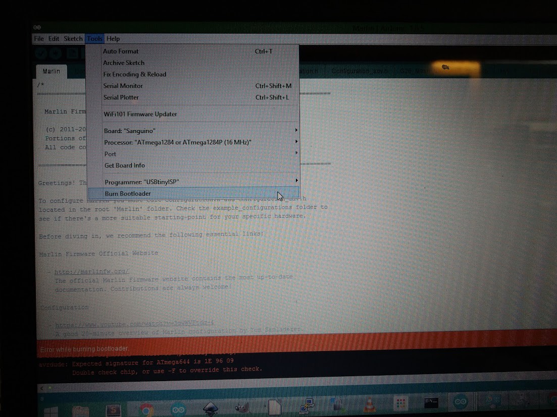
Set our programmer (In this case USBtinyISP), however you can also select "Arduino as ISP" if you are using an arduino to burn the bootloader.
![]()
Burn baby burn. (This isn't as cool as the apollo guidance computer, but I couldn't resist.)
![]()
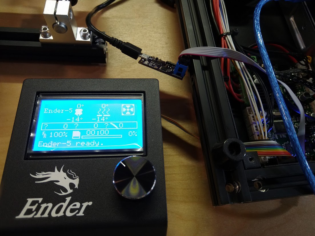
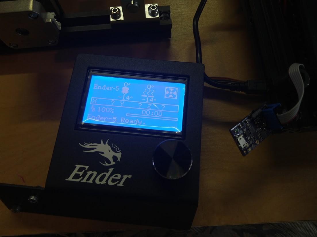
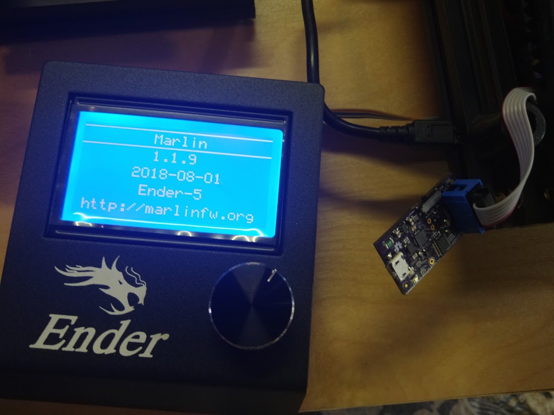
You will then be greeted by a blank screen when you put power to the control board. We can then see if we have appeased all the programming and hardware gods by attempting to compile and upload the Marlin 1.1.9 software I have previously prepared using the Arduino IDE.
![]()
Okay, that's a good sign, let's navigate a little.
![]()
Perfect! No more catch your lab on fire firmware, it's gone now.
![]()
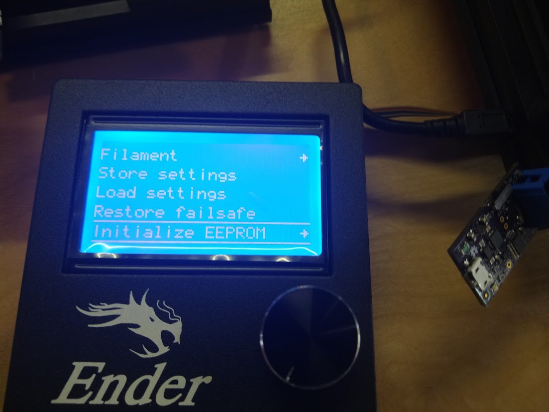
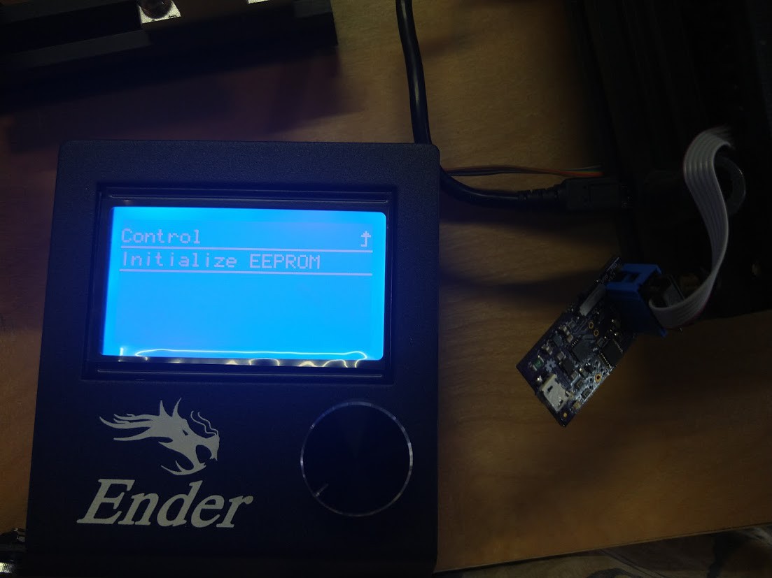
Now we have to initialize the EEPROM and clear it out. We don't want any monkey business if we press this thing into service.![]()
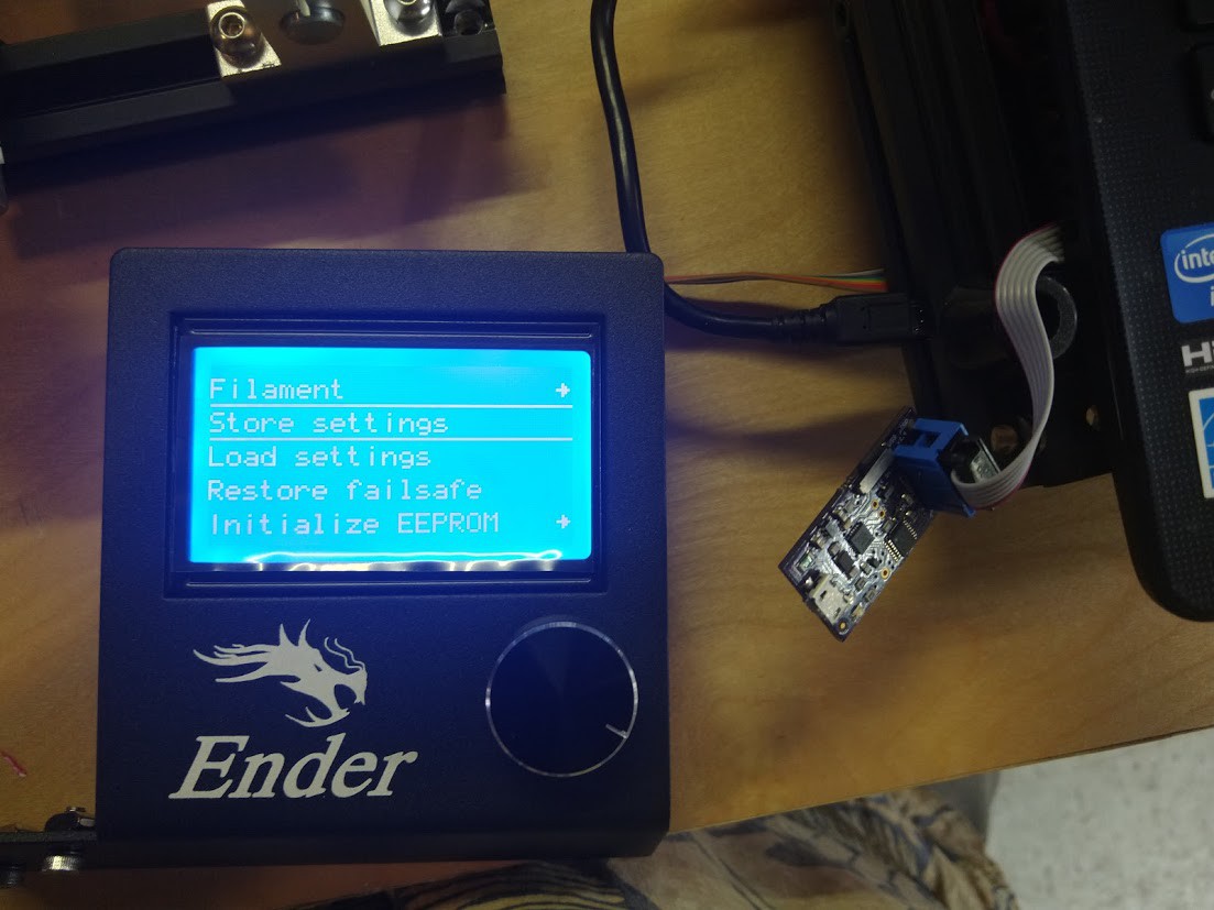
Once this is done, let's just go through and store settings.
![]()
With that done, we've just dedicated a lot of time on a control board we're going to pull out of the printer! AMAZING! (However it will be quite useful if anything should happen to the fancy pants control boards we are going to install next).
![]()
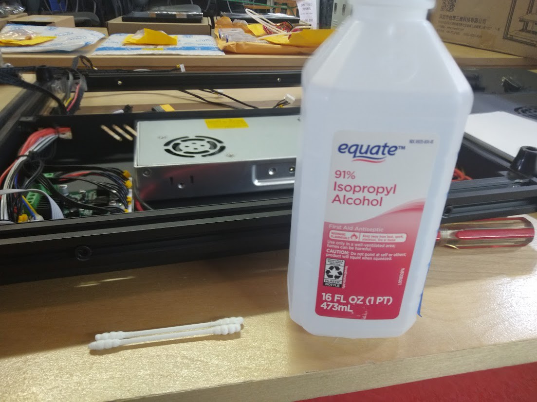
We shall start our removal process, not with screws, but with Isopropyl alcohol. Now why you ask is that needed for a printer control board?
![]()
Well you see there's a layer of hot melt glue over all of the connectors. If I just start pulling these out without getting rid of the hot melt glue, the connectors along with their sockets will come right out! That's frustrating.
![]()
Isopropyl alcohol isn't going to hurt anything, so let's just get it over everything we're going to remove.![]()
Get them soaked well, let it permeate the hot melt glue, and before it dries, you'll find that the connectors are easy to remove, and you can even peel the hot melt glue off the connectors and wires with ease.
![]()
I am now following the EZBoard installation manual, and I am going one connector at a time with this. I am super happy that they made sure all of the screwholes are away from components on this board. There are actual Phoenix Contact branded connectors on this bad boy, and everything looks pretty good. Fuse is a bit offset, but not a huge deal.
![]()
All stepper motor wires hooked up.
![]()
I would like to make a note here, as stated in the manual, the fan for the control board cooling and the fan for the parts cooler are swapped around, just like they are in the SKR Mini E3 V1.2 board. So it's not a complete 1:1 swap, if you swap boards, the location of this will matter and will have your blower going 100% while your control board cooks itself with no cooling fan until a job starts (if the fan is commanded on at all that is). As one slightly famous crazy Aussie bloke may say "Trap for young players!".
![]()
So we put the parts cooling blower into the correct socket. for this new board.
![]()
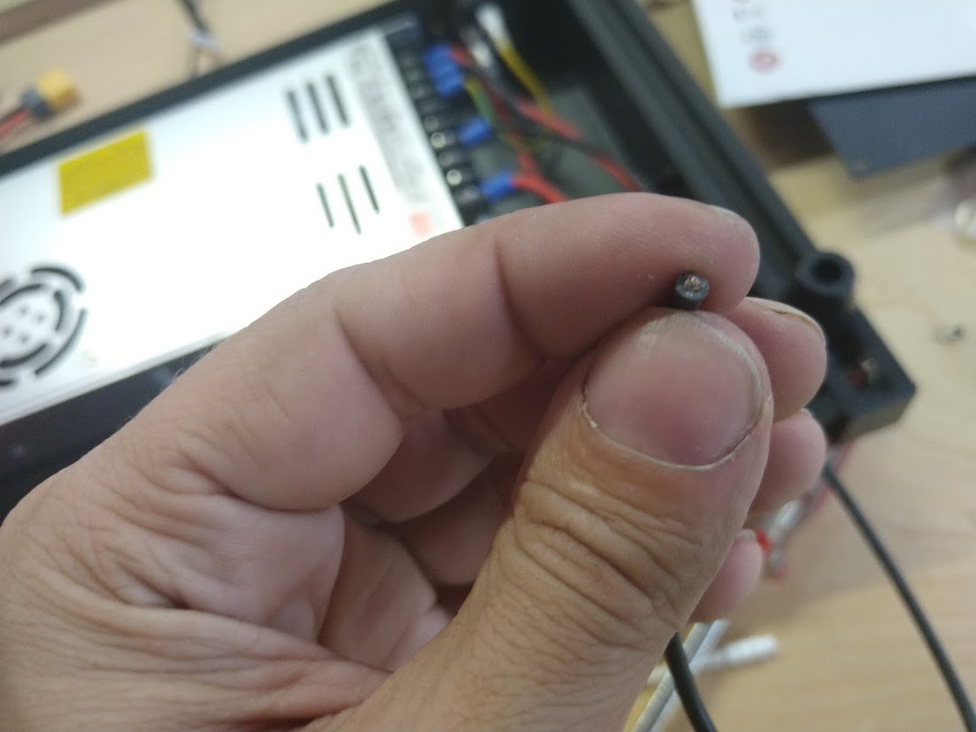
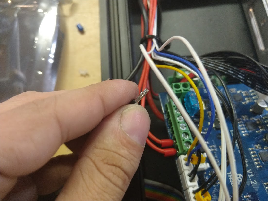
What we have here is a tinned lead. The fine folks at TH3D often joke that tinned wires are 'a terminal issue'
![]()
I for one am going to take their advice here. That means our leads will be bare wire or ferrule crimped connectors when installed into their control board.
![]()
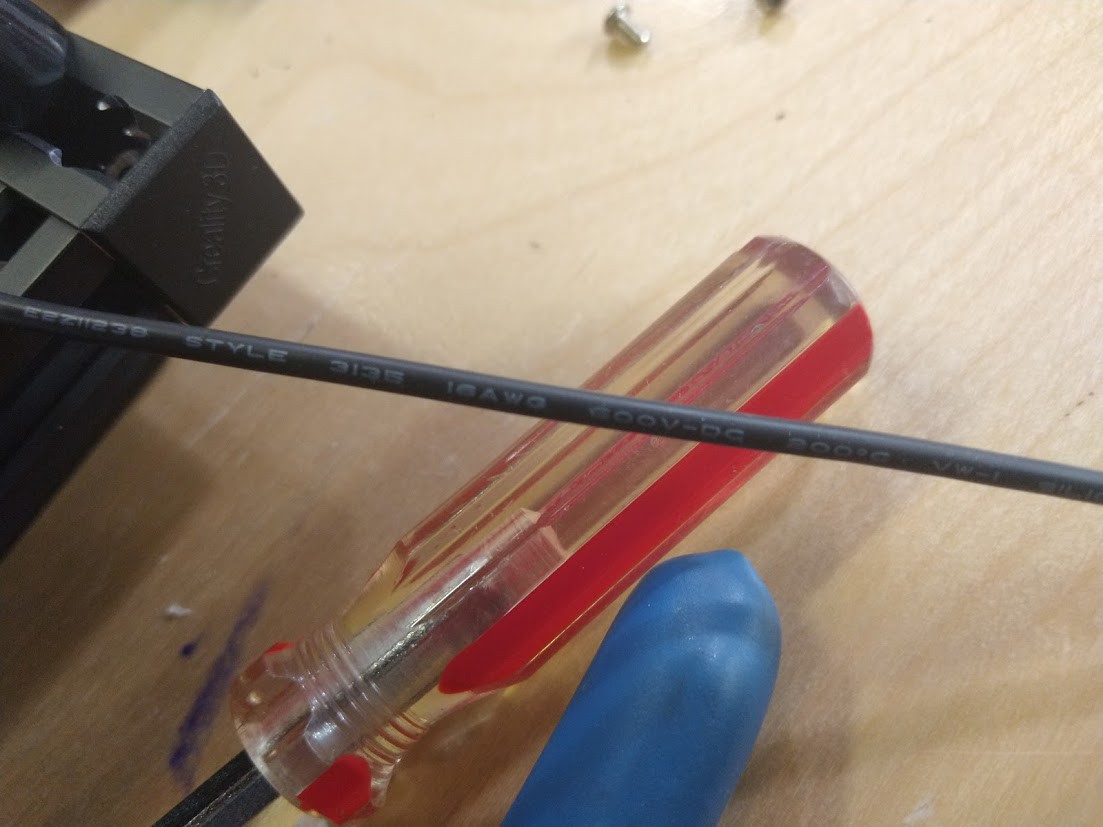
Looks like we've got 16AWG stranded wire here. We need to know this to strip it without damaging the wire.
![]()
Cut off the end, we don't want to see any more solder.
![]()
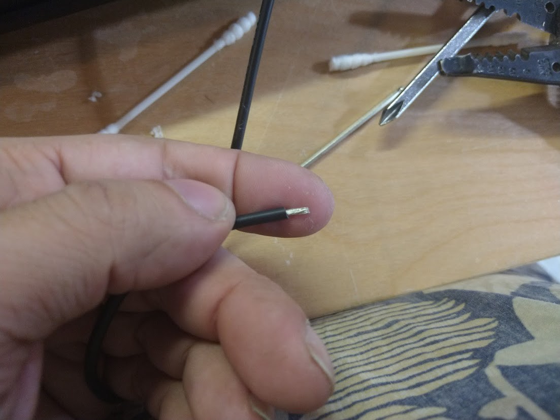
Strip it to the proper length using the proper tool and position.
![]()
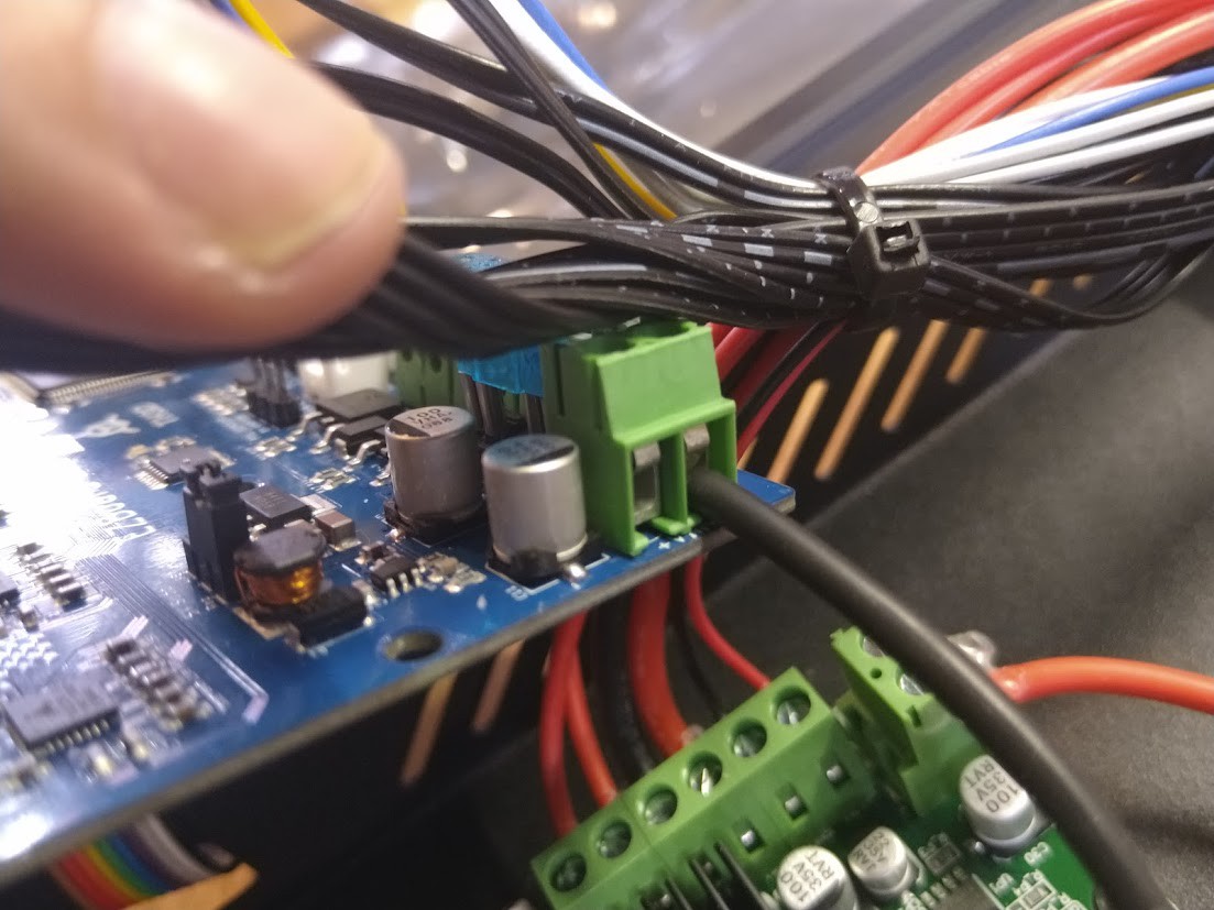
Install the wire, and tighten down the contact.
![]()
Let's put a ferrule on these!
![]()
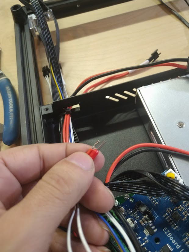
First we look at it, determine the size of the wire (we'll need it in a moment), cut the tinning off, and strip the wire to the proper length.
![]()
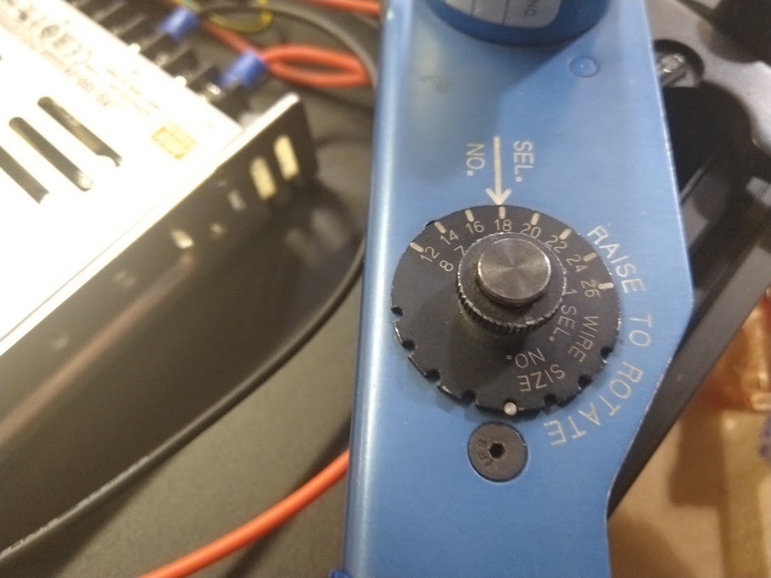
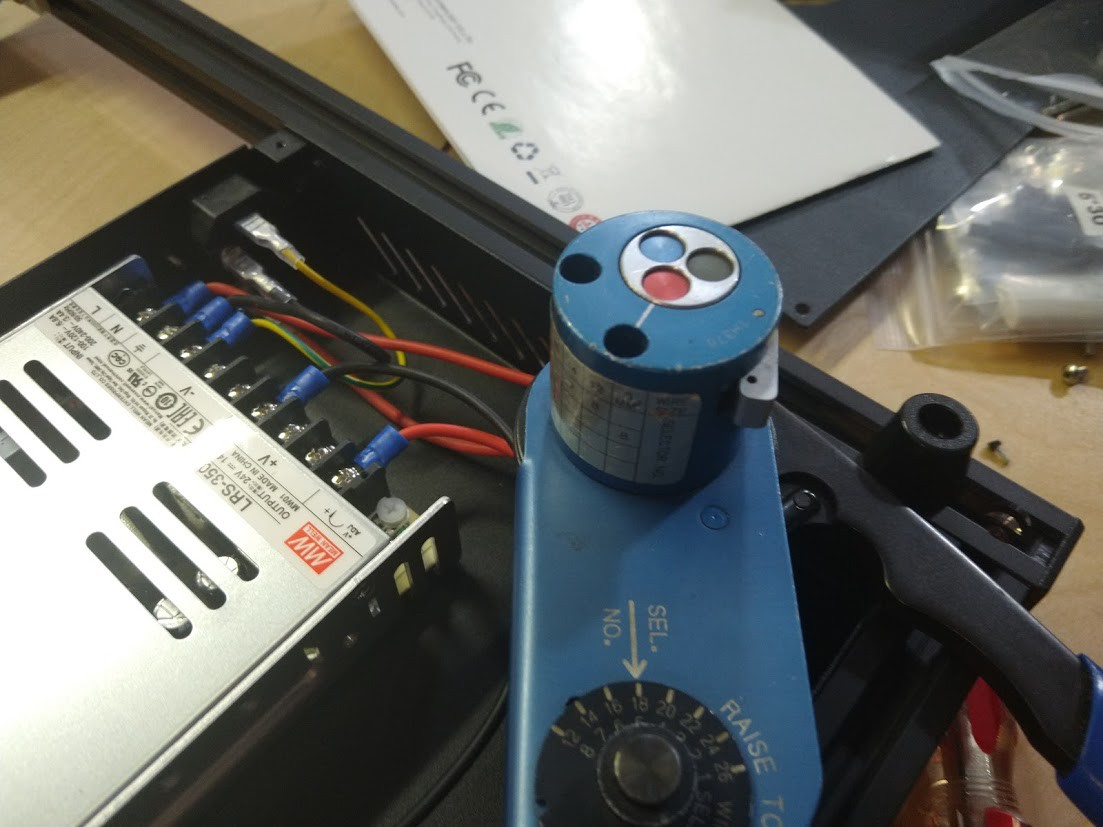
We'll use the guide on our tool to set it up.
![]()
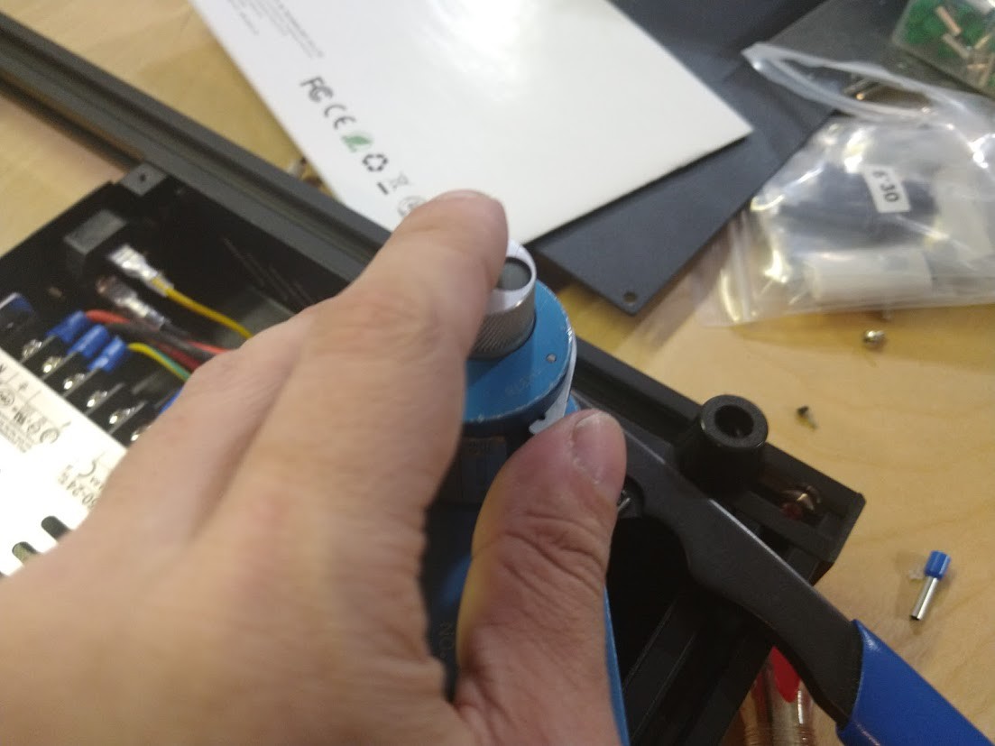
We press the lever to release one of the selections we can make. Tools like these are satisfying to use!
![]()
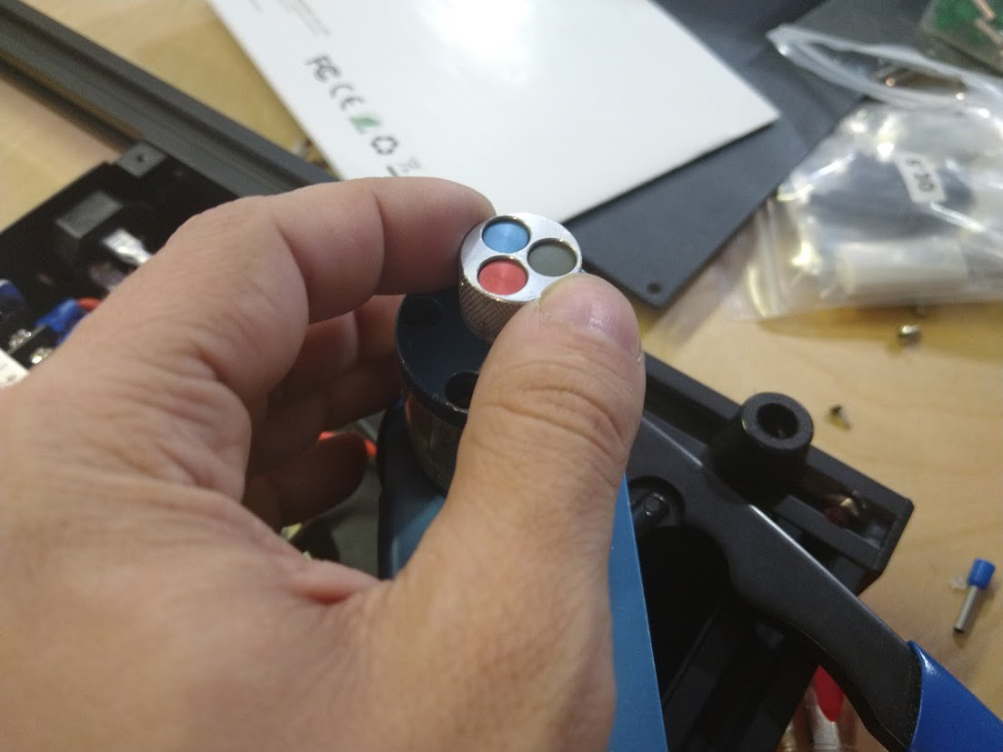
Red is the one we want this time around.
![]()
Satisfying clunk!
![]()
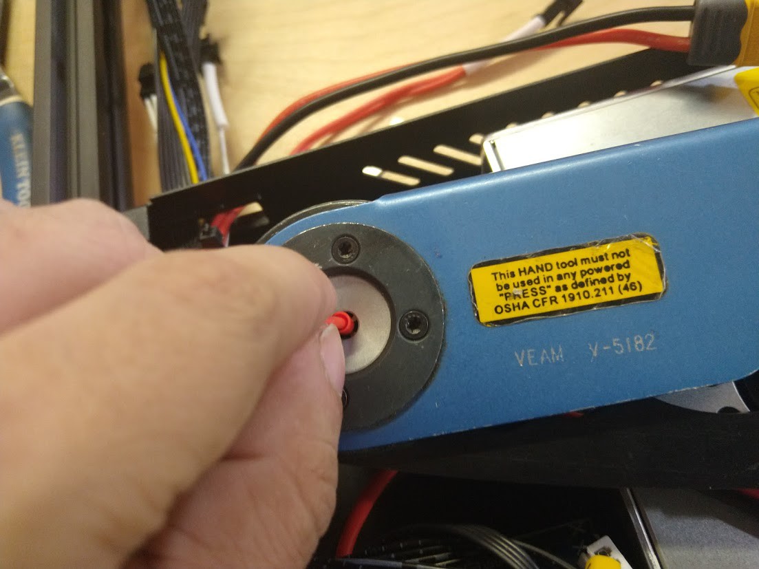
Insert the crimp first, press on the handle until it just catches the crimp, the push your wire in, then crimp all the way.
![]()
If you did this part right, you should not be able to remove the crimp without destroying the wire.
![]()
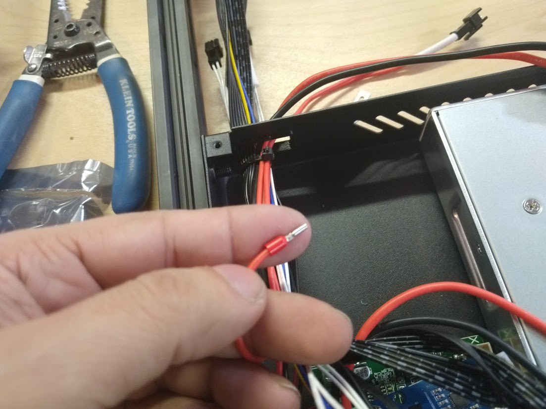
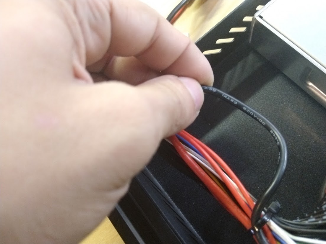
Looks like we got some 14AWG this time.
![]()
Strip, rinse, repeat.
![]()
It took me longer to write up the steps I did than it did to install that power supply and control board. Oh, while we're at it, let's just go ahead and...
![]()
Set that power supply.
![]()
Okay, better!
![]()
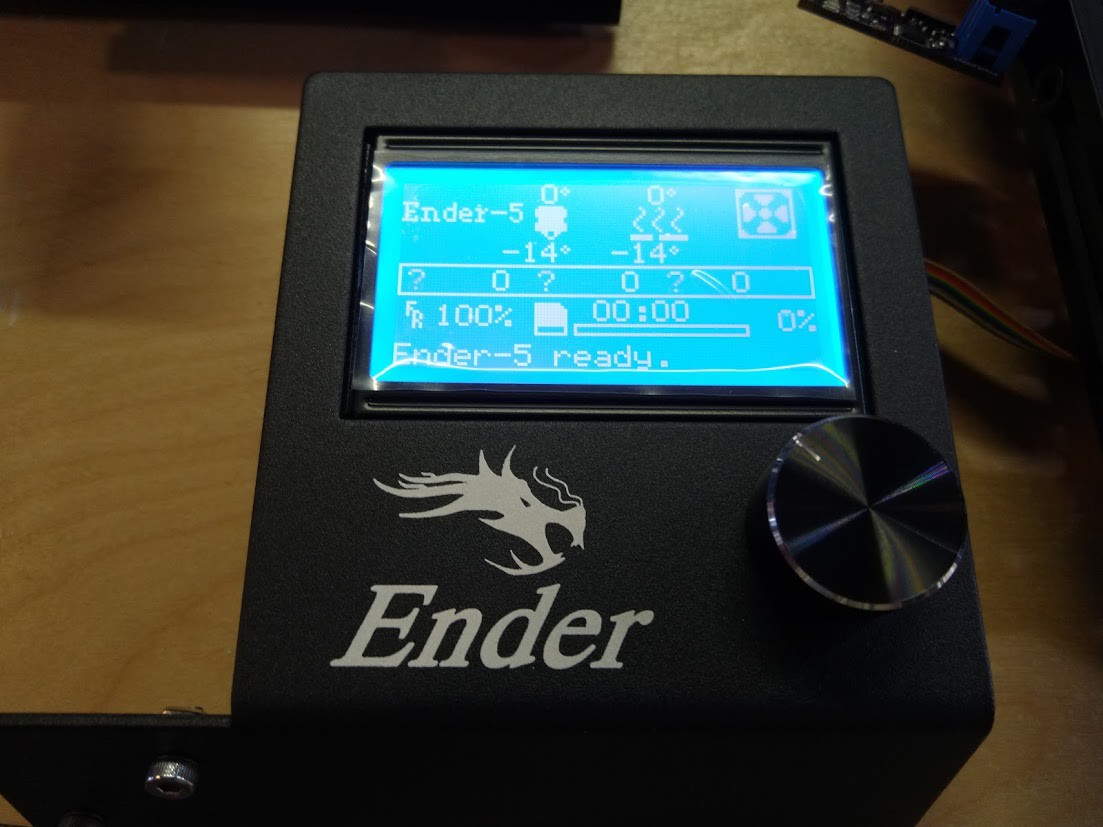
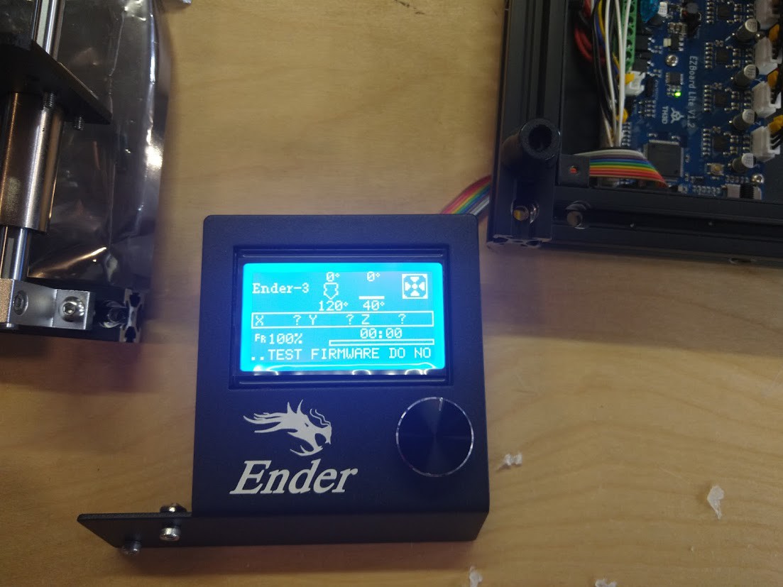
I gave it some power, and the following screen came up! This is awesome!
![]()
Time to install the board fan and button this up.
![]()
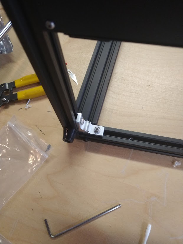
I then took this moment to tighten every screw and fastener on the bottom of the machine. I left no screw untested, first by unscrewing, then tightening to make sure no loose or stripped screws come back to ruin our day later on.![]()
Time to put the frame together and make this thing look more like a 3D printer.
![]()
Let's get this out onto a tray, NICE!
![]()
This is where I need more hands to take the picture and show what I am doing. The goal here is to make the gantry move smooth by adjusting the bearings with the cammed lobes to make them just tight enough. I've found they come a little too tight from the factory and cause issues. I want it so I can still slip the plastic bearings barely under pressure, similar to how one might set a hydraulic lifter in a car engine. Once the gantry moves back and forth with no bumps and no 'jaggy movements', hills or valleys, I can then mount this to the printer.
![]()
Whoa partner! But not until I make sure every bolt and screw is tight, this one wasn't. Gotta test all of them you know!
![]()
It's starting to look like something now!
![]()
After making sure everything is tight on the Z axis, time to mount it to the rest of the printer.
![]()
The feeling of progress.
![]()
Now is a good time to put our 3D printed strain relief on the heated bed.
![]()
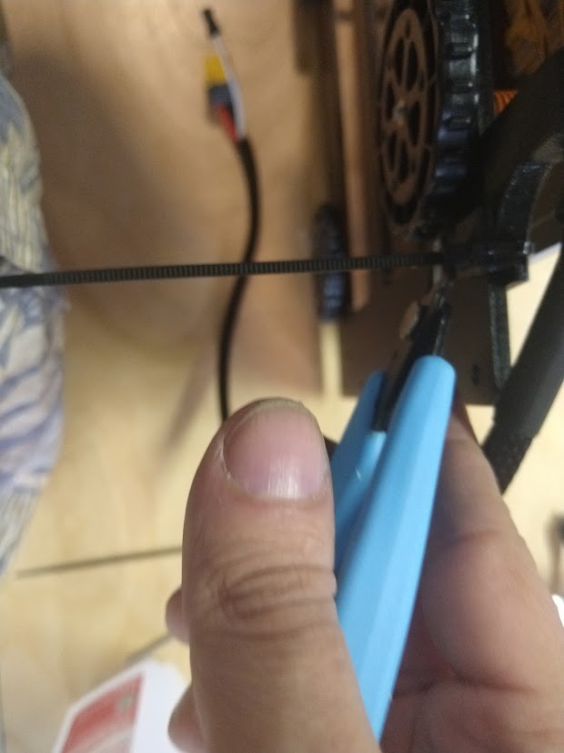
Always clip your zip ties as close as possible with a really sharp pair of cutters, make sure that no one can cut themselves on the zip tie end.
![]()
Let's get the otther tie wrap in place.
![]()
A job well done, let's get this thing mounted now.
![]()
I might get to print something soon!
![]()
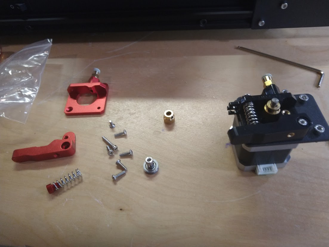
Time to get our alumunum feeder assembly parts out and see what goes where.
![]()
Seems okay, but also seems like I am missing parts.
![]()
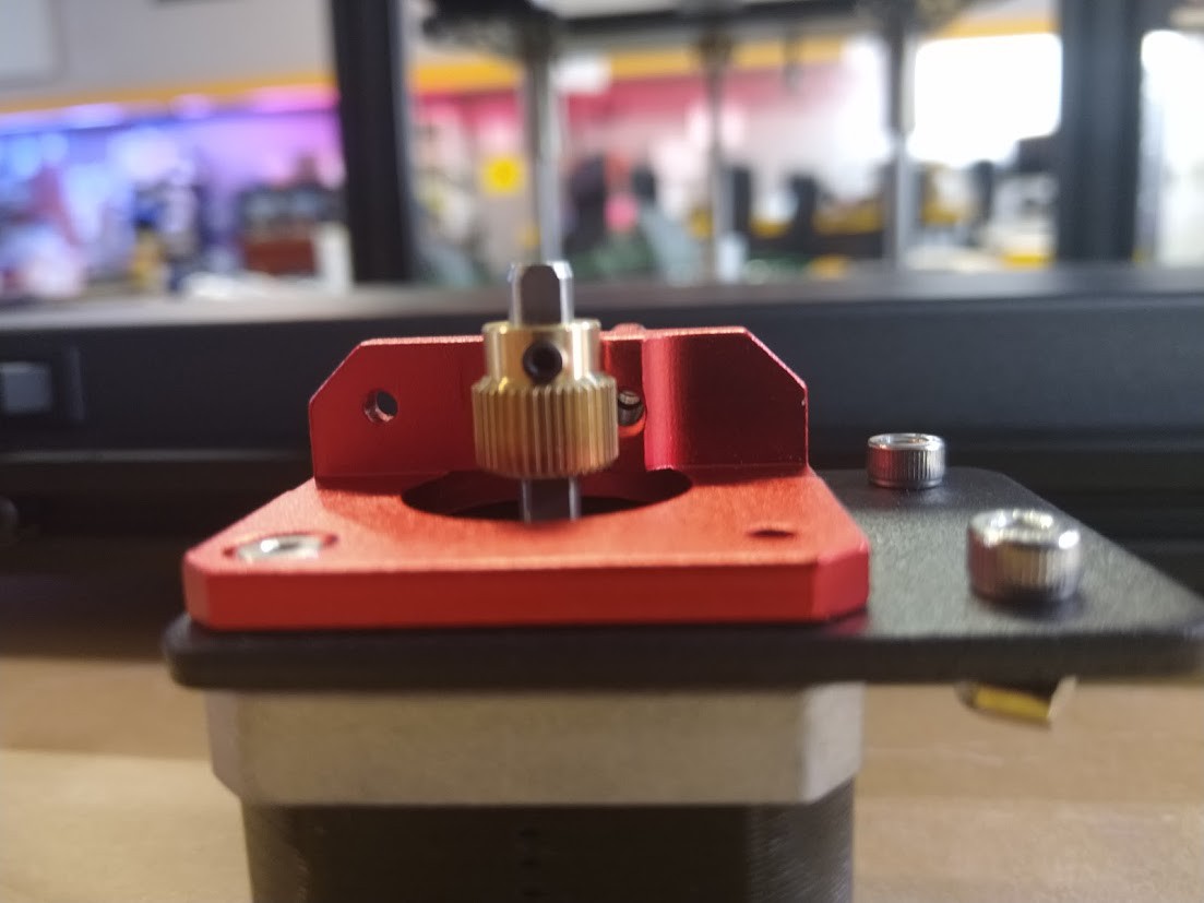
I've alligned the gear to the center of where the filament goes in.
![]()
The pressure assembly seems wrong, and I had to use a couple of parts from the old feeder assembly, but it is together and appears to work.
![]()
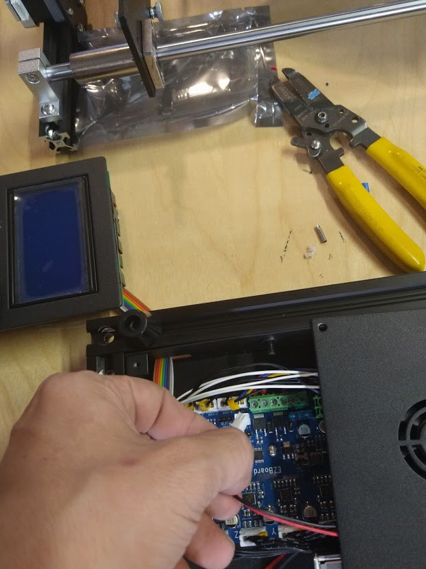
I'm hooking up all the wires to where they need to go, and putting the display in place.
![]()
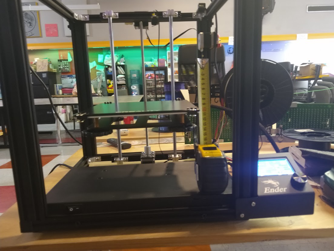
I managed to not take pictures of me installing the tempered glass bed, so just imagine before this picture there is one of me attaching the print bed with binder clips.
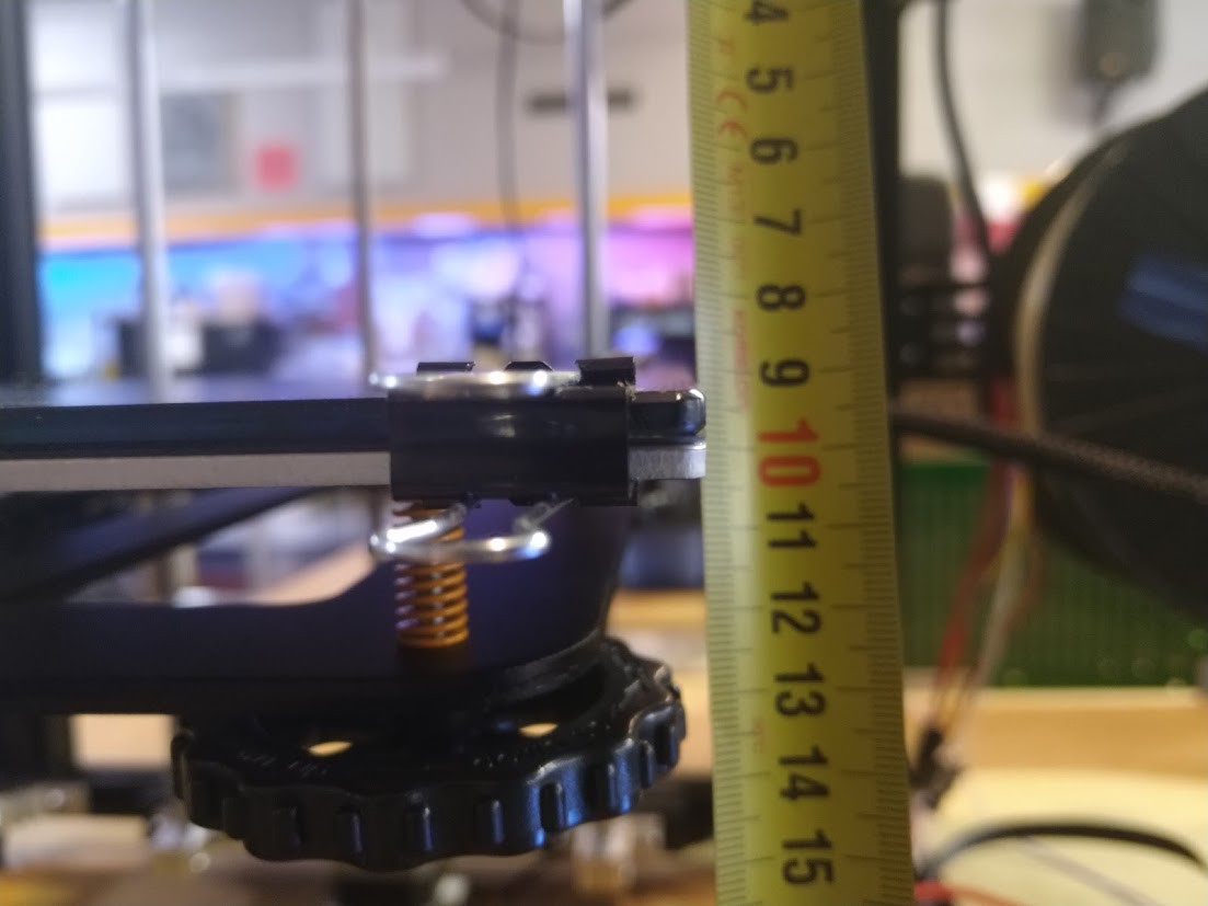
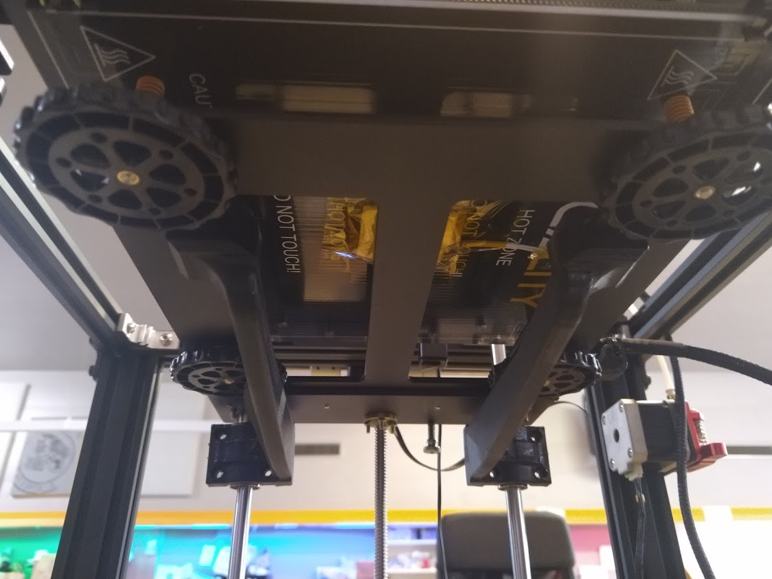
I've put power to it, and gotten out my super duper helpful metric tape measure! I can move the axis back and forth with the test firmware, even though it is for an Ender 3, and get some information I need. The main one is to find out if my leadscrew takes more turns to go 10MM than the original leadscrew they used for the Ender 5. This will come into play when I make the firmware for it.
![]()
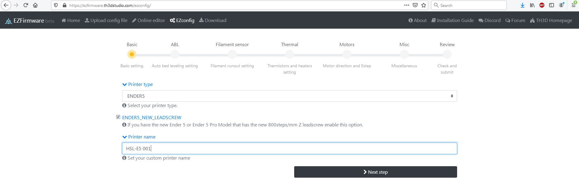
When I attempted to move the Z axis 10mm, it only moved 5mm, this means that the new style leadscrew was installed on this printer. This gave me everything I needed to build the firmware.
So I went to
https://ezfirmware.th3dstudio.com/ezconfig/
![]()
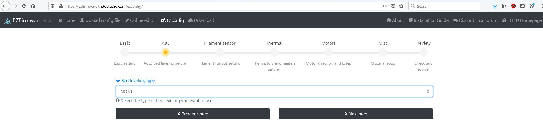
And then set what I needed.
![]()
We'll have to come back to the bed leveling once that stuff arrives.
![]()
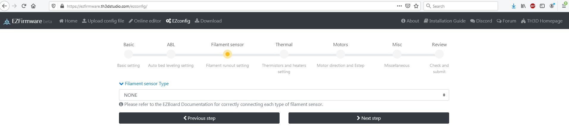
I'm not sure where I am going to mount the filament sensor just yet, so I'll get back to this once we get some operating time into the printer.
![]()
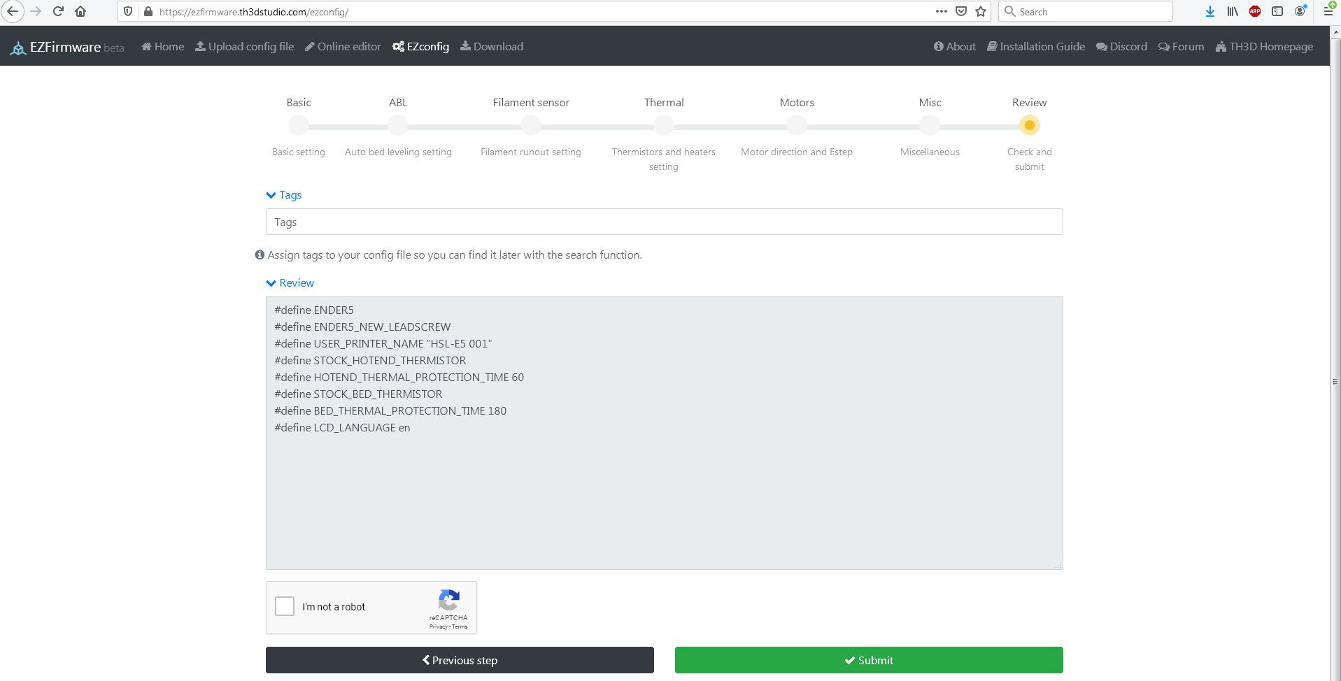
No other changes were made, so I put it in queue and got a firmware spat back out.
https://ezfirmware.th3dstudio.com/download/11613
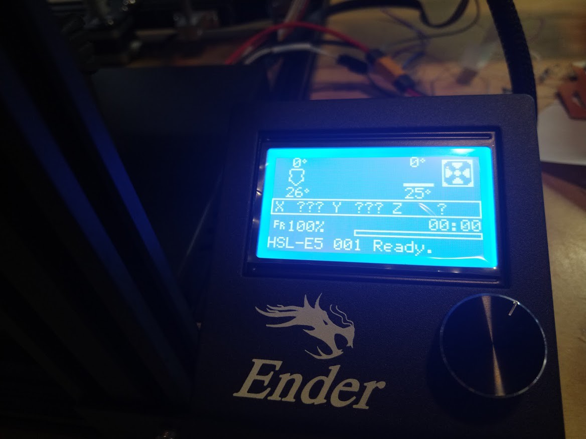
Put it on a microSD card, put it into the printer, turned it on.
![]()
Well that was painless!
![]()
Half installed my bed supports, because the Thingiverse file does not say what nuts and screws to use, so someone else has the job of figuring that out.
![]()
I messed with the Z axis and limit switch quite a lot before I got it where I wanted it.
![]()
I brought everything up to temp, did a basic bed alignment, found out there's a dip in the center of this tempered glass bed (so I will have to shim it with aluminum foil as I did my own personal printer), looked for smoke, smelled for burning, loaded some filament and AWAY WE GO!
https://photos.app.goo.gl/szuDZ66WvsH2xH7N8
![]()
Always good when your first try works.
![]()
![]()
![]()
So with that, the printer works, has been put into where it will live for now, some of the 3d printed parts I made were added to it, and we've got a few lingering issues.
1) The Z axis tray appears bent, not sure if this is because of my supports, or other issue.
2) The Z axis squeaks
3) The bed has a dip in the center (needs to be shimmed out)
4) Filament sensor not installed (have to figure out best place to make it easy to still load filament)
5) BLTouch is not installed due to parts not being here
6) Rpi's not in stock yet
and obviously
7) Second printer cannot be built until it shows up.
This has been fun, and I will revisit it once we get the second printer and the BLTouch kits in.
All in all I am way happy with the result, and once the printer gets tweaked and the pandemic dies down a bit, I look forward to seeing what this beast does when we abuse it and put it through it's paces.
As a result of the way I did this, each printer will have:
A Spare power supply
A Spare control board
A Spare complete Hotend (from PTFE tube all the way to the nozzle itself, including heater cartridge and thermistor)
A Spare extruder feeder
Still to be determined is replacing the sleeve bearing 24 volt 40mmx10mm fans (and the blower) with something quieter and more reliable, sleeving the wiring with something easy to get off and on, and once Octoprint is going deciding on what webcams (or possibly RPI-Camera module) we will end up using, along with the possibility of a fancy pants touchscreen for Octoprint.
Edit 09/02/2020 : It was noted that I did not show the installation of the belt covers I had printed for these machines (Thanks again @ marvthegrate!) , so I am retroactively adding this in below:![]()
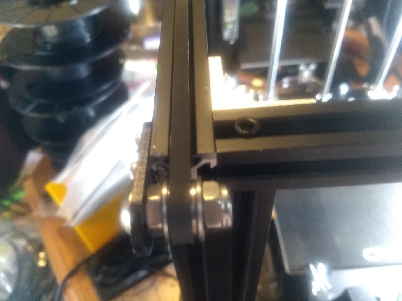
The covers I had printed will just snap fit onto the railing of the printer. This is the X axis gantry left side belt/dust cover.
![]()
The process is similar for the other parts I printed and put on the machine:
![]()
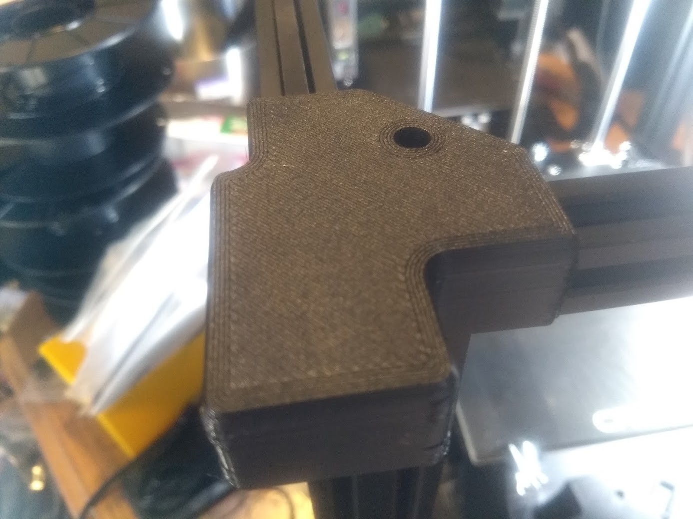
Front left hand side cover shown here being placed
![]()
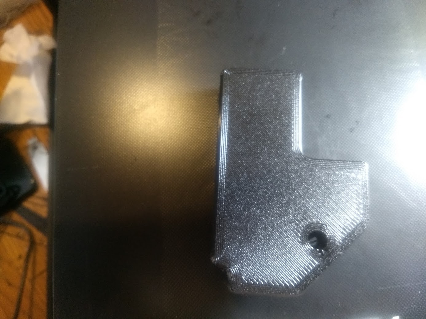
Rear left hand cover
![]()
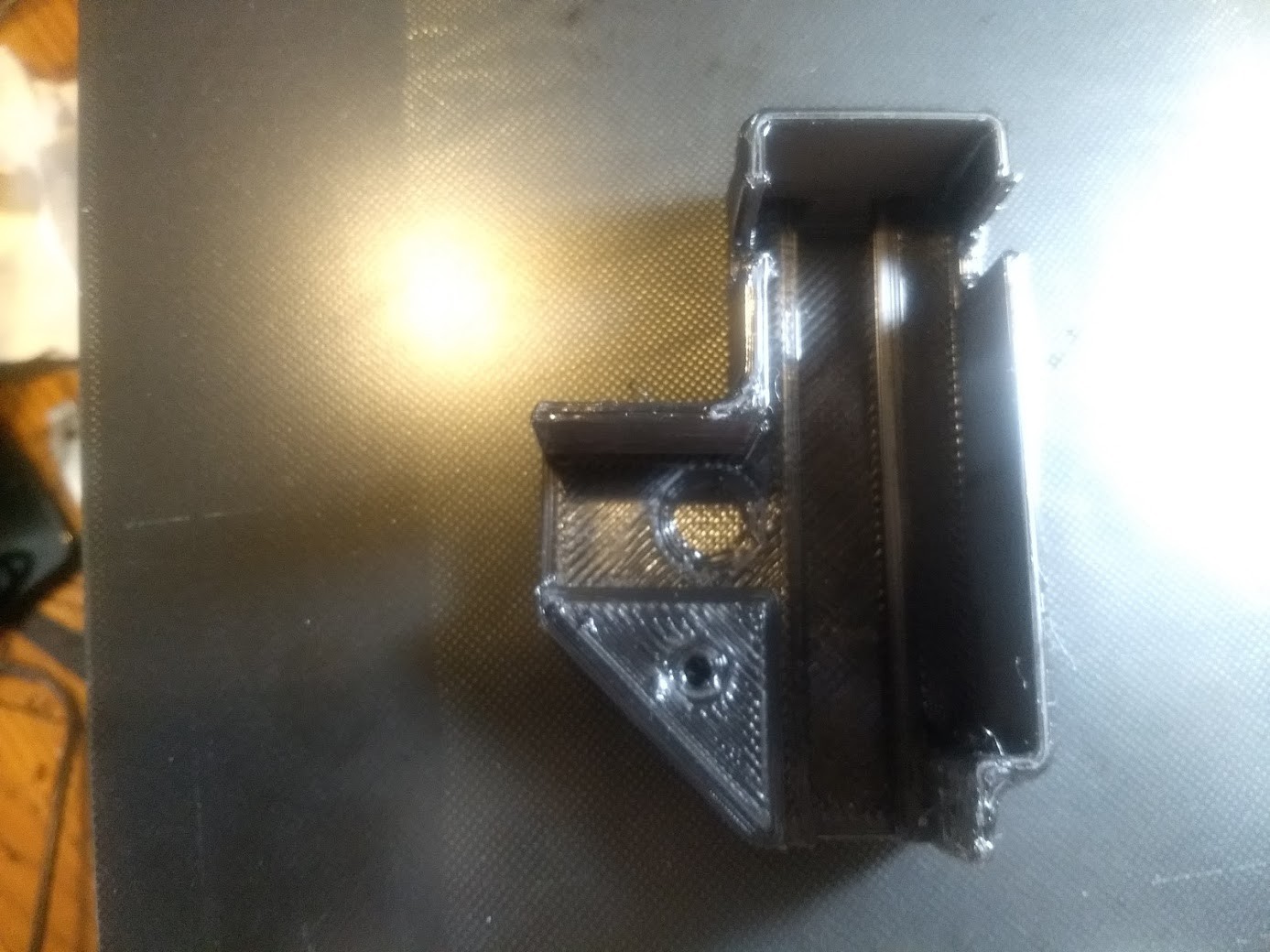
Front right hand cover. It should be noted the parts for the most part have a countersunk hole so you can add some screws if you don't want them to be as movable.
![]()
So if you need a more robust mounting solution for your covers rather than the snap fit, just grab some metric hardware about the right size and you're good to go
![]()
I chose on these machines though to keep the covers loose/snap fit as to make servicing easier, but that could change as more fingers get near the machine and we gain operational experience.
Some notes on the covers though, I did not install the X axis gantry right hand side, or the rear right side covers (even though I printed them) due to the fact different mounting hardware would have to be obtained for the gantry one, and a limit switch would have to be moved from it's stock location on the rear right cover. I feel that there is merit in leaving as much of the movement of the machine stock for future repair/understanding of the machine. I did leave the parts with each machine's box of parts so we can change our minds at a later date.
-
Most parts ordered 03
06/07/2020 at 20:26 • 0 commentsAll of the parts are on their way or have been shipped now.
Both Ender 5 printers were shipped out, the TH3D EZBoard Lite V1.2 boards became in stock and were purchased with a filament sensor. Still not able to get the Raspberry Pi Model 3B's, but adding octoprint to these is not something that is needed for initial operation and modification.
https://www.th3dstudio.com/product/ezboard-lite/https://www.th3dstudio.com/product/ezout-v2-filament-sensor-only-replacement-spare/
I have decided against moving any of the endstop limit switches to keep these as stock as possible. This also means that for the moment I will not be using the second rear right Y axis cover, as it requires another bracket for moving the Y axis limit switch.![]()
A little tangent, probably belongs more in my Ender 3 Pro build and mods page that I am making, however it was my backup plan in case the original boards I had decided on did not arrive or could not be ordered.
Since I got my Big Tree Tech SKR Mini E3 V1.2 boards in and had some time to configure and mess with them I have determined there are certainly oversights in the engineering that stop these from being used on my hackerspace's printers.
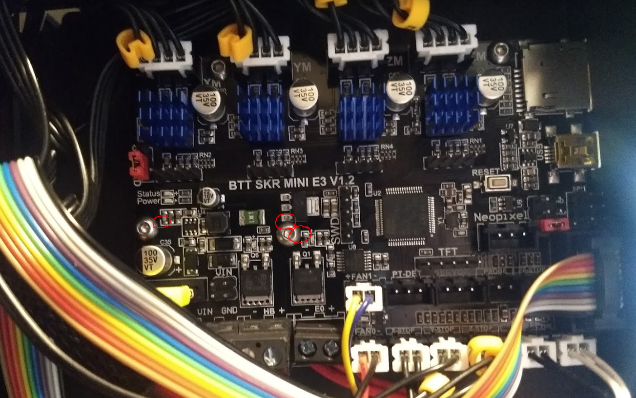
![]()
Some of the screws are REALLY CLOSE to components and it would not be farfetched that if these boards were ever removed that if the utmost care was not taken in putting it back into place that one or more of these components could be shorted to the chassis or eachother. I had to angle my own board to avoid any kind of contact of components against screws, and I would say if you are using stock mounting hardware on Ender 3 or Ender 5 printers and have this board, you should check your own installation to make sure nothing shorts out. I have not consulted the schematic or board layouts to confirm exactly what would happen though. I have been told that they have increased clearances in the SKR Mini E3 V2 board that they will be offering soon.
Anyway, while it's fine for my own machine, I will not be babysitting the ones at the hackerspace, or doing the bulk of the maintenance over their lifetime.
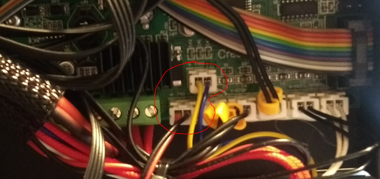
Also interesting is that the "FAN0" and "FAN1" options on the SKR Mini E3 V1.2 are swapped around compared to the stock Creality v1.1.4 board.
![]()
So it is not a 1 to 1 install (Very close though!)
Miss this fact, and the fan% speed of your parts cooler will instead be controlling the fan that cools your control board, and your parts fan will be running 100%
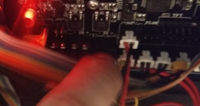
![]()
^ So do this, not the other thing! Trap for young players!
I have also decided to start working on the format for the google document that will be printed for physical documentation, and kind of deciding how I want that to look.
https://docs.google.com/document/d/16c49D2hAlmgXGwfXPbLPVt4-z9uCsGNumb_vEArCTAw/edit?usp=sharing
I would like there to be physical documentation, likely in a 2" 3 'slanted D ring' binder in page protectors, a google doc, a PDF hosted on our wiki, the documentation of the build here hosted on hackaday.io as well as details on our Google Groups page, that way we have redundancy. I am literally making this up as I go along, and I think it will start getting more cohesive as I actually get all the parts together and build the printers up and get to the point of operating them.
I will be updating the stock creality v1.1.4 boards with stock marlin software (likely the same v1.1.9 firmware I am using on my own Ender 5) to use as backup units in case the fancy boards have some sort of failure. This will include burning a bootloader on them, pushing custom firmware to them (to ensure important things like thermal runaway protection are indeed enabled), and making sure that they function as intended.
I want each printer to have a tacklebox of parts, and some kind of modification/repair log. Since we're replacing the control boards and the power supplies on each printer,each machine will have available as spares:
1 stock power supply (original generic unit, likely a Landy brand, I might actually tag it "TEMPORARY USE ONLY!")
1 stock Creality V1.1.4 board loaded with custom Marlin firmware
1 extra complete hotend (from the teflon tube all the way down to the nozzle) just in case anything happens
1 T-nut kit
1 plastic spring loaded feeder assembly
Other than that, I have not yet decided what I am going to do about the fans and blowers that are used in this printer, but I do want to make them serviceable, and I do want to switch them to parts less likely to fail.
There are 2 24volt 40mmx10mm fans (one cooling the control board, and one cooling the heatbreak), and a 24 volt 40mm blower assembly that is used for parts cooling. All of these fans are relatively loud, and are sleeve bearing. Upgrading these to maglev or ball bearing would likely help out with service life and noise, and installing some form of removable connector on both the fan and the blower on the hotend would allow for easy swap outs if filament gets stuck in them, or the fans fail.
-
Printing parts 02
05/27/2020 at 01:14 • 0 commentsThese X-Axis gantry covers are printed in 3DFuel Midnight Black Workday PETG at 257C with a 25% cubic infill with a .6MM nozzle on a Ender 5 running Marlin 1.1.9 firmware on a stock v1.1.4 control board using Cura as the slicer
Ender 5 X-Axis belt covers by D_jespersen
https://www.thingiverse.com/thing:3465579/![]()
![]()
![]()
^ Example of Left side X-Axis Gantry cover installed (Snaps into place) on my Ender 5.
These Y-Axis covers are printed in 3DFuel Midnight Black Workday PETG at 257C with a 25% cubic infill with a .6MM nozzle on a Ender 5 running Marlin 1.1.9 firmware on a stock v1.1.4 control board using Cura as the slicer.
Ender 5 Y-Axis belt covers (Front Left and Front Right) by D_jespersen
https://www.thingiverse.com/thing:3412007![]()
![]()
![]()
![]()
^ Example of where Front Left Y-Axis cover is installed, and it installed on my Ender 5.These Y-Axis covers are printed in 3DFuel Midnight Black Workday PETG at 257C with a 25% cubic infill with a .6MM nozzle on a Ender 5 running Marlin 1.1.9 firmware on a stock v1.1.4 control board using Cura as the slicer.
Ender 5 Y-Axis belt cover (Rear Left) by D_jespersen
https://www.thingiverse.com/thing:3412007![]()
![]()
![]()
^ Example of Rear Left Y-Axis belt cover installed (Snaps into place, but can be fastened if needed).
I have printed the Rear Right Y-Axis covers, however I am unsure if I am going to install them, as they will only work with the stock location of the Y Axis limit switch if modified, and the file does contain a printable mod to move the limit switch, it's just I do not yet know if I am going to use it yet. I do want to keep as much of the motion system stock as possible to make future repairs easier and more straight forward.
-
Printing parts 01
05/26/2020 at 22:42 • 0 commentsThis heater bed strain relief was printed in 3DFuel Midnight Black Workday PETG at 257C with no infill with a .4MM nozzle on a Ender 3 Pro running Marlin 2.0.5.3 firmware on a stock v1.1.4 control board using Cura as the slicer.
Ender-5 Bed Strain Relief by derandi3d
https://www.thingiverse.com/thing:3443100/![]()
![]()
![]() ^ Example of same part fitted to my own Ender 5, to relieve stress that could occur on the heater bed wires.
^ Example of same part fitted to my own Ender 5, to relieve stress that could occur on the heater bed wires.This cable protector was printed in 3DFuel Midnight Black Workday PETG at 257C with no infill with a .4MM nozzle on a Ender 3 Pro running Marlin 2.0.5.3 firmware on a stock v1.1.4 control board using Cura as the slicer.
Cable protection for Ender-5 by lgaga
https://www.thingiverse.com/thing:3354725/![]()
![]()
^ This snaps into the box containing the power supply and the control board where all the cables come into. I have not added this mod to my own printer, as my printer is working very well right now and I have another method of protecting the cables in place already (Don't fix what isn't broken!), however these will be installed on the new printers as all the wiring needs to be removed anyway for the board swap.
-
Printing parts 00
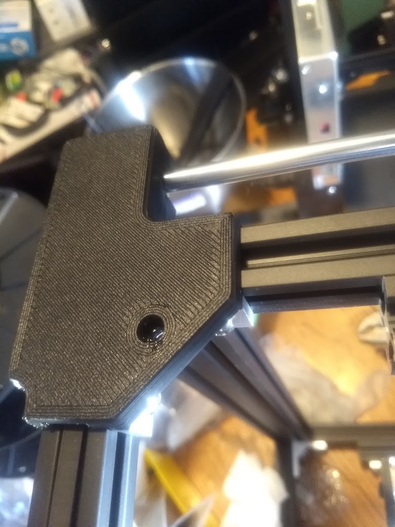
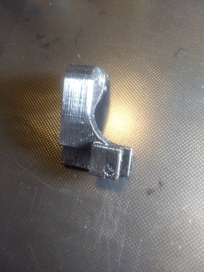
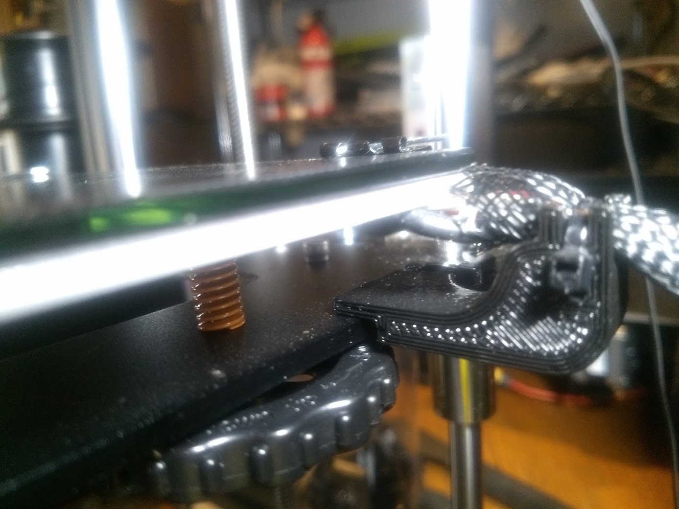
05/26/2020 at 22:31 • 0 commentsThese bed supports are printed in 3DFuel Midnight Black Workday PETG at 257C with a 25% cubic infill with a .6MM nozzle on a Ender 5 running Marlin 1.1.9 firmware on a stock v1.1.4 control board using Cura as the slicer.
Ender 5 Bed Supports by BoothyBoothy
https://www.thingiverse.com/thing:3661405![]()
![]()
![]()
![]()
![]()
![]()
![]()
![]()
![]()
^ early attempt at a dry fit of a earlier printed arm showing location of the left side bed support arm installed on my own printer.
-
Start of project after proposal was completed.
05/17/2020 at 00:47 • 0 commentsI put in a proposal to our hackerspace to procure and modify 2 Creality Ender 5 printers.
I wanted to upgrade them with 32bit controller boards and what should be a more reliable power supply compared to what they come with. The idea was to get 2 printers at less than the cost of a new Ultimaker, since our Ultimaker 2 is on it's last legs. I wanted to run 2 identical printers with identical mods, and have a stock of replacement parts for them too. The idea behind that was I wanted to be able to cobble one functional printer out of the two, should they go down for any reason. Two completely modified Ender 5's are still way less money than a Ultimaker 2+ would be, so I figured it was worth a go based on the ownership I have had of my personal Ender 5 unit.
I like the fact that these things have a really large community behind them, that the power supply is enclosed in a metal box below the unit, and servicing the Ender 5 is quite a bit easier than the 3 is. All motors, wiring, hotend, etc are easily accessible without removing the bed from the unit. Also in my thought process was the fact that we don't have to worry so much about clearances or things people might put on the table behind or in front of the printers, as the bed only moves on the Z axis. One stepper motor per axis removes some complication from troubleshooting issues too.
Details of the proposal were archived on our Google Group, link below.
https://groups.google.com/d/msg/heatsynclabs/x5iwoCGOclw/KcPPCF7zAQAJ
The 3D printers were ordered as were most of the spare parts and non-3d printed mods that are going onto this printer. We're still waiting to see if the TH3D EZBoard Lite V1.2 boards ever go back into stock, and if they don't, we'll be ditching them to use BIGTREETECH SKR MINI E3 V1.2 or V2 boards instead.
I am currently using my own 3D printers at home to print some mods for the printers, and to get the parts ready for assembly. Some mods are easier to install prior to the printer being put together.
The current list so far
Heatbed cable strain relief
https://www.thingiverse.com/thing:3443100Snap-in cable protector
https://www.thingiverse.com/thing:3354725X-axis belt/pulley covers
https://www.thingiverse.com/thing:3465579
Y-axis belt/pulley covers
https://www.thingiverse.com/thing:3412007
Hotrod Ender 5's for the hackerspace.
Build log of 2 new 3D printers for Heatsync Labs hackerspace (www.heatsynclabs.org)


 First print done with the OctoPrint and the Capricorn tubing. Not a lot to complain about here. Also did a print without the painters tape on the other machine, and it came out great as well.
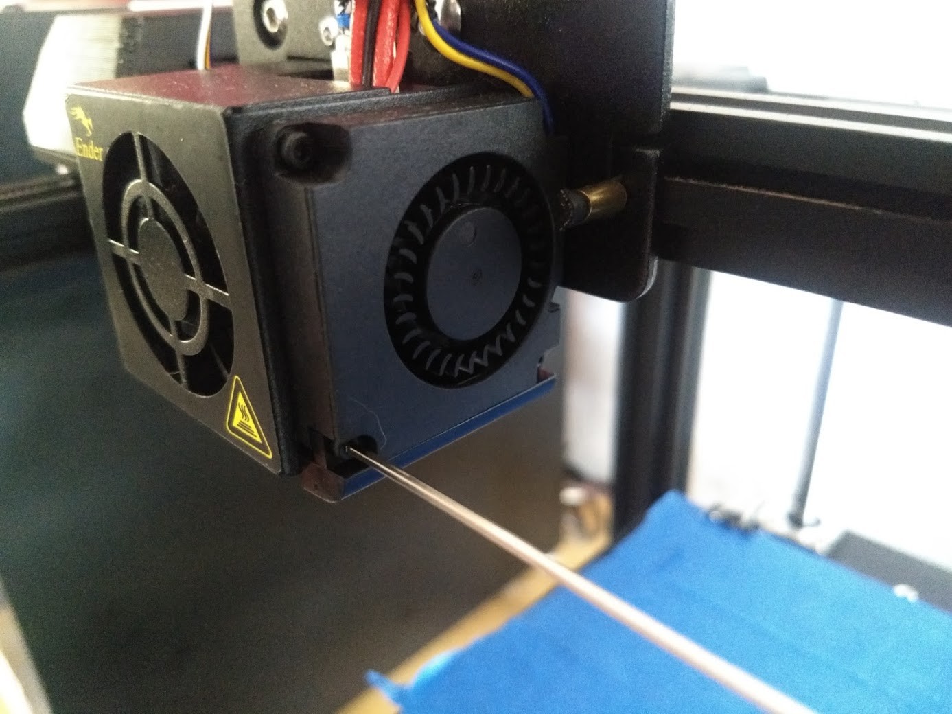


 I managed not to take any pictures of using Velcro and Zip Ties to affix the BLTouch wiring to the rest of the printer. I then made a quick test print to make sure everything was in order before hooking the wiring of the BLTouch to the controller board, and everything seemed to be in order.
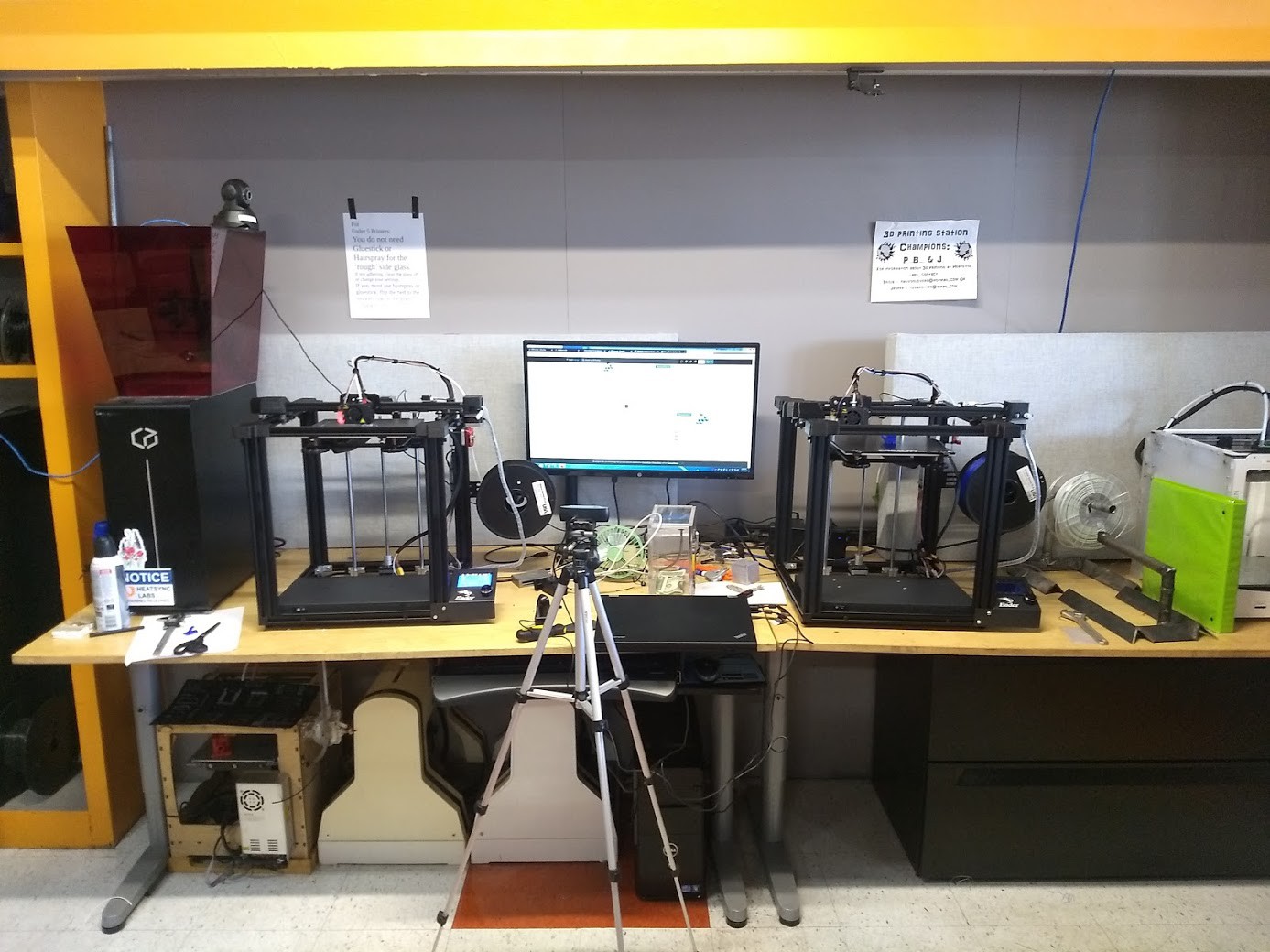


 ^ Example of same part fitted to my own Ender 5, to relieve stress that could occur on the heater bed wires.