rand3289
-
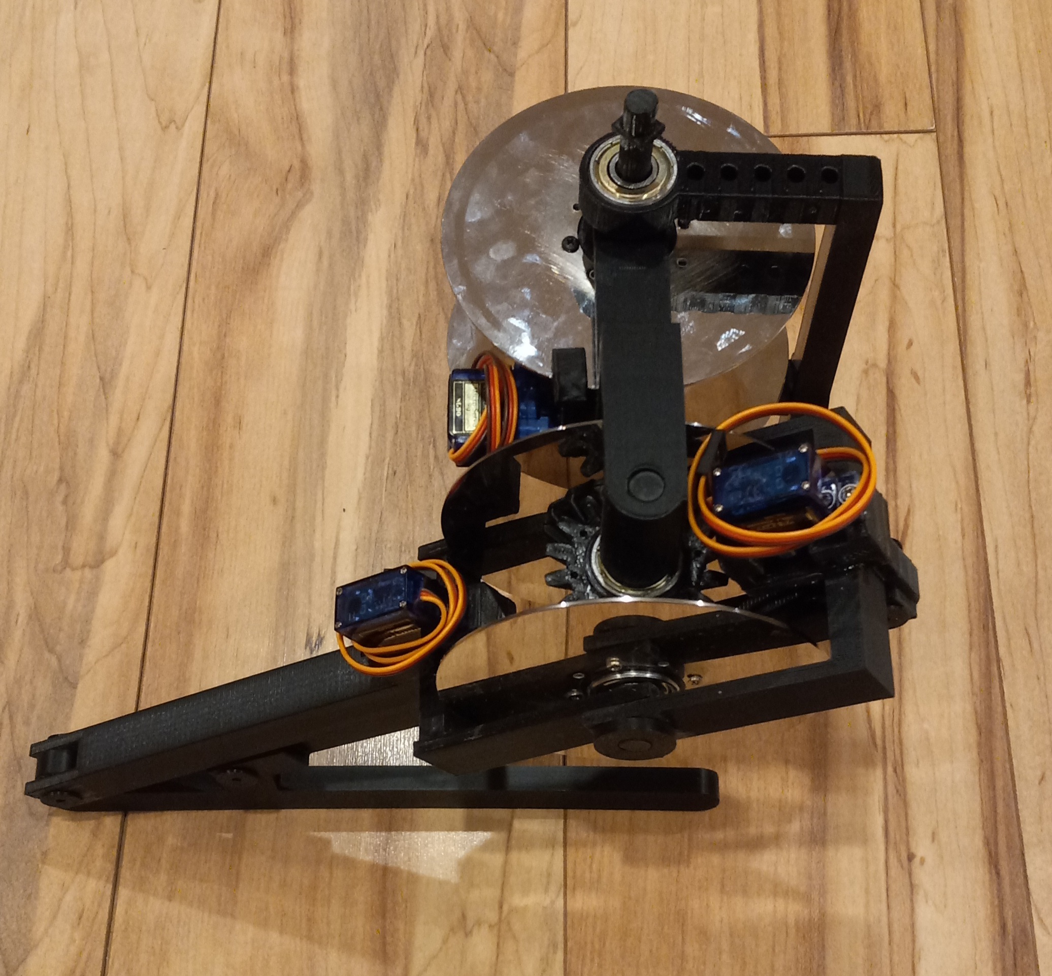
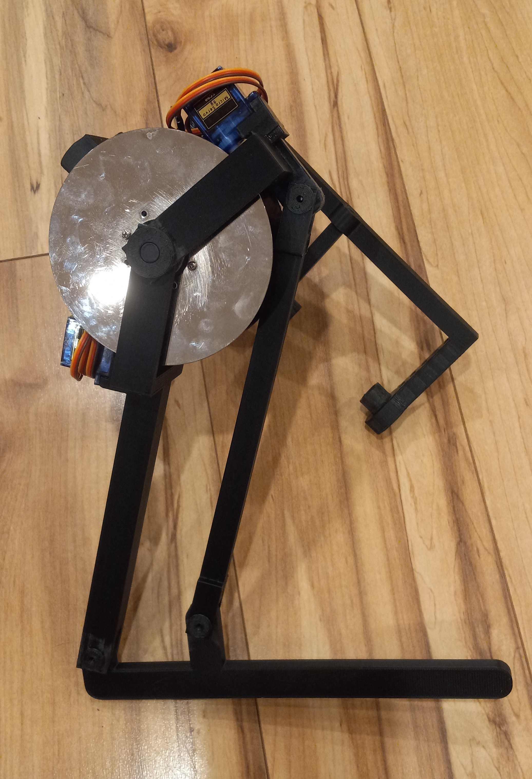
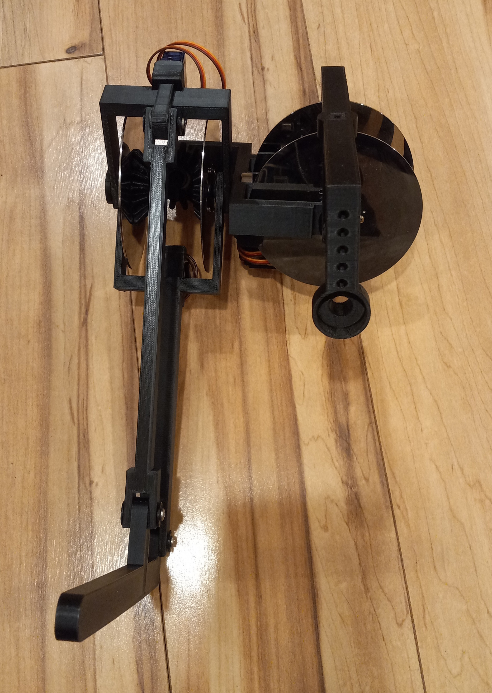
Latest prototype
03/08/2022 at 06:09 • 0 comments![]()
![]()
![]()
-
Video of Braker bot in action!
10/11/2021 at 03:38 • 0 commentshttps://cdn.hackaday.io/files/1719247355596416/BrakerBot_2021-10-10.mp4
I've finally figured out how to build a brake for the bot! It took me more than a year of thinking. The sg90 servo based brake is super simple. This is a video of the brake without brake pads in action. I am controlling the servo with a servo tester.
-
Other clutch based actuators
07/24/2020 at 21:25 • 0 commentsSomeone found this on reddit:
https://www.reddit.com/r/robotics/comments/hvbxyf/this_2dof_compliant_actuator_has_only_one_motor/
https://scholar.google.ca/citations?user=nJ9rSQwAAAAJ&hl=enHere we see that clutch based actuators can have an awesome performance. Here is the bad part:
https://patents.google.com/patent/US20190184551A1
https://patents.google.com/patent/US9566715B2
Another interesting project based on MR fluid actuators:
-
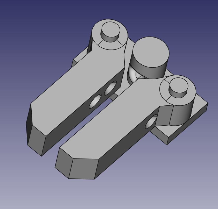
Brake calipers
07/13/2020 at 08:55 • 0 commentsI am thinking along these lines for a brake caliper actuated by a servo.
![]()
Jaws will be pushed apart by a spring. They will be pulled together by cables attached to each jaw and going through the center of the base. Jaw ends will have 2x8x14 mm slices of pencil eraser glued to it.
-
Eddy current brake failure :(
06/29/2020 at 00:20 • 0 commentsI've made the eddy current brake. It has about 14 m of 20 AWG magnet wire wound about a chain link. It has about 0.5 ohm resistance.
![]()
I tested it by holding the disk spinning at about 450 rpm in the slot of the chain link. The magnet was in my hand. I briefly applied about 10 V from a 30 A variable power supply. I felt NO FORCE during the time the coil was energized. It got warm within seconds so there was a lot of current ( my calculations tell me about 20 A) flowing through the coil. At this point I call my eddy current brake a failed experiment. It could be the magnet, it could be the low RPM or the thin aluminum plate.
Rumbling and whining:
This thing was hard to make and it didn't work. I had to buy magnet wire on line, drive to buy a chain in the store, drive to the beach to get sand for annealing process. I've spent about 40 minutes heating the chain in the sand with a propane torch which after all probably didn't change the magnetic properties of the metal much but made it a lot softer to cut and bend. I had to unspool the wire to a larger spool so I can measure how much wire I will be winding which took about an hour. Hours of research on winding magnets, trying to figure out wire resistance, max currents, weight and other crap. Then I had to wind the coil which took me about two hours. I didn't want to connect it to the power supply directly since it had such a low resistance so I had to wire some resistors in parallel to lower the overall resistance because I didn't have any low ohm resistors. Wire the coil with resistors and a switch in series. Connect it to the power supply. At this point I think my meter died because I tried measuring current through the low current connector. My 30 A power supply's current indicator also died! After all that work I get no force whatsoever from the brake. At this point I think I need to take a chill pill called fu*kitall and move on to a different type of brake. -
Eddy current brake take II continued
06/19/2020 at 06:09 • 0 commentsI got 14 links of 5/16" (8.8 mm thick) zinc coated chain. It is 18.25" long. They weigh 533 grams. Link's outer dimensions are about 28x48 mm. It was US $2.97 per foot @ homedepot.
I also bought 1 lb of 20 AWG magnet wire for around $16 US on Amazon. 1 lb of wire should be about 323 ft and I am hoping to use it for 3 breaks. At about 1 Ohm each. I need 14 total for 7 DOF. $5/brake $75 total. Each brake will be about 190 g. 2646 g (5.8 lbs) total.
This is getting heavy and expensive... (OR not https://temcoindustrial.com/20-awg-copper-magnet-wire-5-lb-mw0027-magnetic-coil-red-soderon155.html OR https://temcoindustrial.com/20-awg-copper-magnet-wire-5-lb-mw0167-magnetic-coil-gpmr200.html) I was hoping to make the whole robot for under $100.
Next thing to do is to anneal it in sand using a torch to improve its magnetic qualities. This should also strip the zinc coating. For this reason I bought zinc coated and not galvanized chain. It is harmful to inhale zinc vapors. Do it outside !!!
After annealing I will cut a slot in each link and try to separate the chain by bending them open. Close the links back and leave about 3 mm gaps for disks to spin through.
Looking at a 1 lb spool of wire it seems big. I hope I will be able to wind 107 ft (32.6 m) around the link. It will take some time :)
I don't know how much current a 20 AWG wire will take. Reference materials on the web state anywhere from 1.5 A wound (http://www.magnetwire.biz/magnet_wire_current.html ) to 18 A for a single conductor in air. The brakes will not be operated at 100% duty cycle. I am guessing 25% max. This might need to be enforced in software. Spinning disks can be equipped with blades for air cooling the brakes. Therefore, I am hoping to be able to operate the brakes at 12 V through IRFZ44 mosfets or MCP14A1202 or even MCP14A09? Anyone has a schematic to recover the conductor EMF energy after it is turned off?
-
Four-bar linkage
06/13/2020 at 21:52 • 0 commentsBy using a four-bar linkage to replace a knee joint it may be possible to eliminate spinning disks at the knee joints! The number of breaks would stay the same. The two from the knees would just move up to the previous (hip) joint. This will increase the efficiency because the number of spinning gears and disks will decrease. Allow disks to spin at higher speeds. Reduce weight and make limbs lighter by moving the breaks closer to the body. Reduce the bulk of the robot. A bipedal configuration will require only 6 spinning disks. This will however put a higher thermal load on the hip joint disks. Also it will reduce the angles by which the joints can turn. This change however leads to a flat hip frame which will be easier to print. And here are my Hand Aided Design (HAD) drawings:
![]()
In this sketch brakes would be mounted on A and B. Shafts and how A sits on the shaft are not shown on the left. Disks are not drawn to scale on the left and omitted completely on the right.
-
Eddy current brake take II
06/10/2020 at 03:58 • 0 commentsCopper Disks:
It would be nice to replace aluminum HD platelets with some copper ones to increase efficiency. Maybe make them smaller and spin them faster? Should I make them copper rings to reduce the amount of copper used and weight? On the other hand disks have larger thermal capacity than rings. Aluminum disks with copper rings attached on both sides?
I need about 10x10 cm of copper sheet to make a disk. Where do I get cheap copper?Plan B for getting an eddy current brake to work:
Buy a short length of steel "coil" chain. Anneal it to improve magnetic properties. Cut it into individual links with a grinder or a hack saw or a sawzall. Individual links will form cores for the eddy breaks. Disks will spin in the groove made by the cut. Wind an insulated copper wire around the link to form an electromagnet. Should I get 1/4" or 5/16" or 3/8" or 1/2" chain? Would it be better to use short pieces of 3/16" thick 1 1/4 square tubing instead? I wish I could find a source of soft iron. Steel stays magnetized.
Now where do I get some cheap copper wire? I don't have any transformers laying around... Scrap metal stores? Aliexpress sells it for about $50/Kg shipped - WTF? Amazon for $32/Kg shipped. Current market price of copper is USD $5.65/Kg. Time to start melting pennies and making my own wire lol... Can I make a copper disk by soldering copper pennies together?
What diameter of wire do I need? What length of wire will fit onto one coil of chain? How heavy is it going to be? If I want to use 12V, I need 106 ft (32 m) of 22 AWG (0.64 mm) wire to get 7A. Alternatively I can use 133 ft (40.5 m) of 24 AWG (0.51 mm) to get 3.5A How much current do I need to create enough eddy current? What amount of impedance will it provide? Is this why people get EE degrees??? Does this whole thing make any sense? Am I just designing my own motors here??? HELP!!! I am lost!!!
-
Eddy current brake
06/05/2020 at 03:27 • 0 commentsI've constructed and tested an eddy current brake. The test was a failure. I used about 8m (30 turns) of 0.33 mm (#28 AWG) insulated copper wire wound into an 85 mm coil. It has about a 1.5 Ohm resistance and rated for 1.4 A max current. Therefore I did not use more than 3V to test it. I will try boosting the voltage a bit more since I don't care about destroying it. However, at 3V and about 450 RPM I did not see any breaking (movement of the tibia). This is not a standard eddy break coil configuration. I wanted to try a core-less design.
I am also working on a new Femur designed to print in one piece. Both eddyBreak.FCStd and femurBlock.FCStd are available in BreakerOne_experimental_2020-06-04.zip
![]()
![]()
-
Gearbox
05/31/2020 at 07:02 • 0 commentsI made a gearbox with about 29:1 ratio that drives the spine shaft of the robot. It contains two 58:11 teeth gear sets reducing the RPM and increasing the torque. The gearbox has 3 3D printed axles supported by 6 ABEC-7 608zz bearings. All gears have a 1.3 mm module. Cad files are available for download.
![]()
I am using a Johnson DC motor rotating at 14000 RPM and consuming 0.7A @ 13.8 VDC without a load. When installed in the robot the motor spins at about 13000 RPM (calculated) and consumes 1.2-1.3 A @ 13.8 VDC. The motor runs directly from a 2.5 A power supply. Disks spin at around 450 RPM one way, as measured by my PYLE laser tachometer and about 520 RPM the other way ( reverse DC polarity ). This is a bit high. Ideally I want under 300 RPM at the disks. This thing is loud and exhibits vibrations. After 10 min of continuous rotation the motor got hot to touch. Motor gear (first gear) and its bearings got a bit warm. All other parts remained cold.
As a result I do not recommend using the gearbox to reduce motor speed. It is best to use a commercial geared DC motor with output shaft speed under 300 RPM. Use a belt or 1:1 gears to connect the motor output shaft to the spine shaft within the gearbox. A small gear on the spine shaft will eliminate the reduction. (see gearBoxOneToOneGear.zip)