Noeël Moeskops
-
PCB tests
08/22/2020 at 15:22 • 0 commentsADS1015
The ADS1015 converts analogue to I²C signal (12 signed bit). This is necessary because there are no more pins left on the ESP32. The ADS1015, part of the ADS101x family supports four analogue inputs and have some nice comparator functions and an interrupt feature, so that there is no need to continuously read the analogue value of a pin but instead be warned when it reaches a certain (programmable) threshold. This does however require that the RDY/ALRT pin is connected to an input pin of the I²C master, unfortunately there are no i/o pins left, so I can't make use of this function.
Driver
The driver created for this IC is straightforward and currently only supports reading of a pin. Normally I create a driver for a specific module, like UART for `comm` or a stepper motor driver for the `control` module, but the ADS1015 can be used by multiple modules so the driver is situated in the `aruna::driver::ADS101x` namespace. In the future I want to refactor all drivers to here to make it consistent.
Files
- `./aruna/include/driver/ADS101x/ADS101x.h` defines the functions that a platform specific drivers should implement.
- `./aruna/include/driver/ADS101x/ADS101x_map.h` contains all the registers in class enums for easy driver writing without magic numbers.
- `./aruna/src/driver/ADS101x/ADS101x.cpp` implements an abstraction function `read(...)` that converts the value from the I²C bus to actual voltage and writes default values to the config register.
- `./aruna/src/driver/ADS101x/portable/ESP32/ADS101x_ESP32.cpp` is the only peace of the driver that is not cross-platform and only implements the physical I²C bus communication.
Adding support for new hardware is really easy, just create a `./aruna/src/driver/ADS101x/portable/xxx/ADS101x_xxx.cpp` file and implement `int16_t readConversion(uint16_t config, uint8_t address)` and all the middleware drivers like `ADS101xWaterSensor.cpp` that uses the ADS101x to read an analogue water level value will work flawlessly on new platforms. In the future I want to make a total abstraction for I²C, so you only need to implement `read()`, `write()` and `setup()` and can then freely use all the I²C drivers.
PCA9685
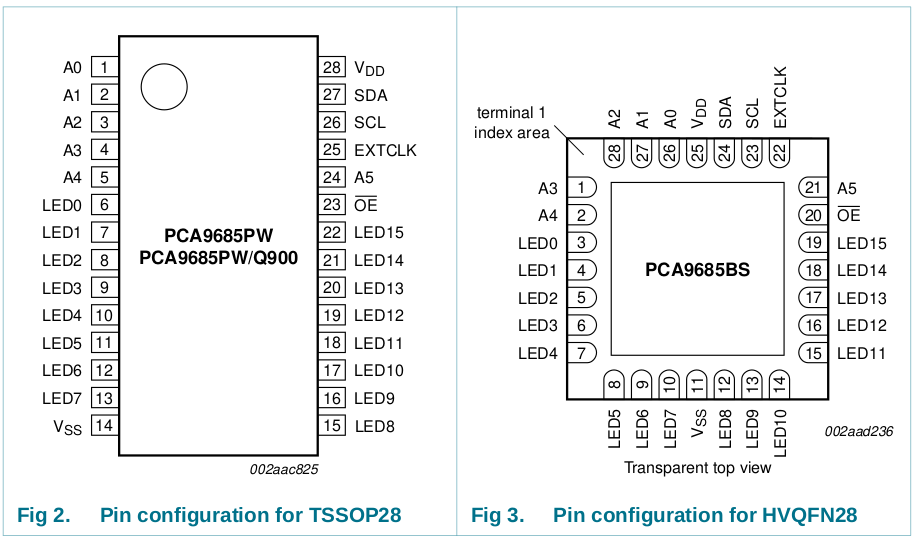
The PCA9685 converts I²C to PWM signal. It supports a total of 16 channels that can all be configured manually. The motor control pins for the SimonK ESCs are connected to the first four connectors while the next four are available through 2.54 mm pin header pins for further expansion. I ideally want to be able to drive the BLHeli motors using Dshot with this IC because now they use four pins on the ESP that I could think of better use for. But that will have to wait for the next iteration.PCA9685PW (left) and PCA9685BS (right) pinout When testing the IC it turned out it didn't acknowledge I²C messages to its address (0b1000000 by default). After inspecting the IC with my microscope I saw that not all the connections were making solid contact. So I re-soldered the chip (two times in total) but still no dice. I then went thought the documentation and it turned out I used the wrong pinout of the PCA9685 in my design. In my initial design I used the PCA9686PW that comes in a TTSOP28 package, this was later switched to the HVQFN28 package because of space limitations. I however did not notice the pin difference between the two packages (see picture above, for example: A0=1 on PW while A0=27 on BS). So the pinout of the PCA9685 make no sense now on the PCB. I might be able to cut some traces and cross wire pins so that the chip can still be used.
LSM6DSOX
The LSM6DSOX is a 3D gyroscope and 3D accelerator sensor that using I²C (or SPI) to communicate the data. I want to use this to measure the speed of the ROV so that I can control the ROV by setting the speed and using control logic like PID to maintain a certain speed. The gyroscope comes in handy to stabilize the ROV and to know the orientation of the device.
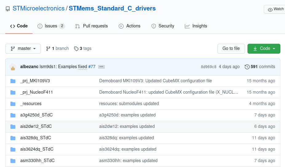
C drivers for STM MEMS sensors: https://github.com/STMicroelectronics/STMems_Standard_C_drivers The LSM6DSOX has a lot of I²C registers so writing a driver from scratch just for testing is quite hard. Luckily it turns out that STM already created drivers for all their MEMS sensors, that need only an implementation of `read()` and `write()` for the platform specific I²C communication. Really some cool stuff. I implemented the platform specific function and ran the "self test" example. The test however, came back negative. It seems that communicating with the chip goes fine up to the point that you actually want to get any gyro or accelerator data of out it. It just returns gibberish. Debugging using a logic analyser shows a lot of I²C communication that all seems to be within the I²C spec. I then tried the Adafruit LSM6DS library for Arduino. This implementation fails to write to the I²C bus at the point of reading any measurement value. Or it gets a buffer overflow when reading data.
Edit: After sending ACK messages as described in IIS2MDC the chip passed the self-test successfully.
BME280
This bosh sensor measure the temperature, air-pressure and humidity. The air pressure and humidity are used to check for any leaks in the hull. By monitoring the humidity for any certain peaks and the pressure for drifting it can be concluded as a leakage. It is important to have multiple ways of checking if the system is in a safe state. If one system may fail then the leak can still be detected by another system.
This was the most expensive component on the board, so I was really hoping to have more luck with it then the last two IC's. Luckily the chip works immediately when using the Sparkfun BME280 library. The Temperature increased when I put my finger on the chip and humidity increased when breading on the chip. Very nice results, I guess you get what you pay for. Only the pressure reading where a bit off and need to be calibrated. But that was to be expected.IIS2MDC
I originally picked the LIS2MDL, a 3D magneto sensor as a compass. But it was unavailable at Digikey. The IIS2MDC was however available and after reading both data sheets the only difference between the two chips I could find is that the LIS has one extra register for 3 wire SPI and a minor difference in maximum value.
The IIS2MDC function is to get the heading (compass) of the ROV, and in doing so complete the IMU (Inertial Measurement Unit) sensor stack. The data is transmitted using I²C. This sensor is also made by STM and a driver is also available in their STMems git repo. I however have not yet come to the point of trying that driver because it is not sending acknowledgements when addressing the IC over I²C. And after some investigation it seems that there was a cold connection between the IC and the PCB.
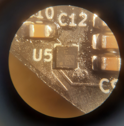
![]()
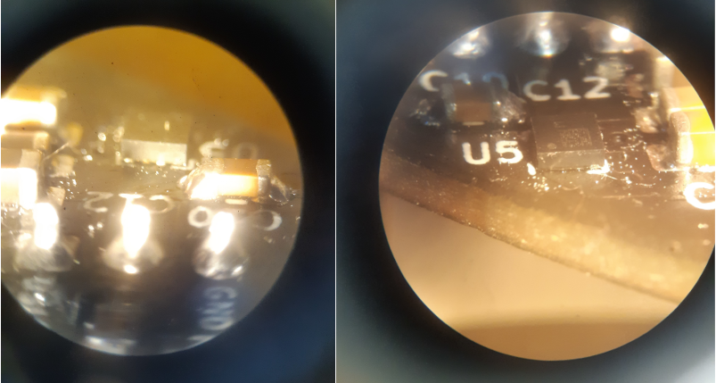
IIS2MDC sensor on the PCB before re-soldering. Some questionable connections can be seen. I removed the IC and discovered that two pads had no solder on (I²C-SDA and one ground pin). After applying some more solder to the pins in question I re-soldered the chip and found that it finally replied to I²C messages :).
![]()
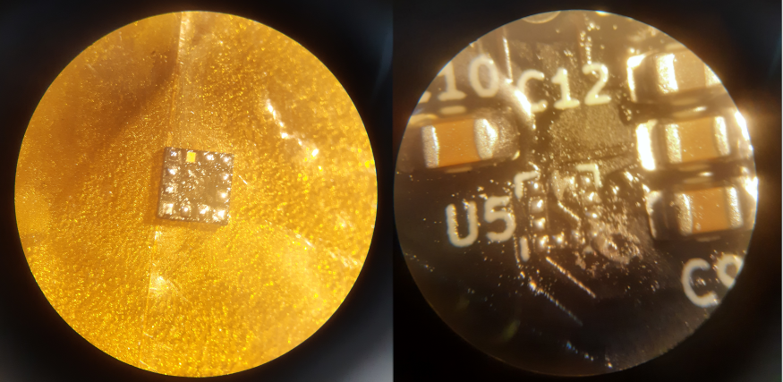
De-soldered IIS2MDC on the right, notice the top pin having any tin attached to it. Right picture shows readding more tin to tin poor areas ![]()
The finished re-soldered chip I could not find any readily IIS2MDC libraries for ESP32 or Arduino to test the functionality of the chip, so I tried an Arduino LIS2MDL library instead since the registers are almost identical. The ESP32 unfortunately called an `abort()` halfway through the test, I did not investigate further since the library compatibility was a long shot anyway. Instead, I tried the STMems C driver but was faced with the same issue as with the LSM6DSOX. Configuring the device went fine but actually doing a useful read of the magneto sensor resulted in failure. Since both sensors were failing in the same way gave me an indication that the chip and the PCB layout may not be faulty. It instead turned out that the I²C read messages were not being acknowledged by the master. I tried sending ACK's before but when I configured the driver that way the ESP would crash, so I left it disabled. Acknowledging all messages except for the last byte works though.
![]()
I²C read of LSM6DSOX, bottom is not sending ACK's thus resulting in the chip not transmitting anymore data. Top is sending ACK's and is receiving all the data After setting the driver to `I2C_MASTER_LAST_NACK` I was finally greeted with "SELF TEST - PASSED". This also fixed the issue with the LSM6DSOX, two birds with one stone.
Only two ICs remain, the MAX6682 over SPI for thermistor reading and the INA219 for voltage and current sensing. But I'm afraid those will have to wait for the next log as this one is getting quite long and I'm tired of debugging all day.
-
PCB's arrival
08/17/2020 at 21:58 • 0 commentsArrival
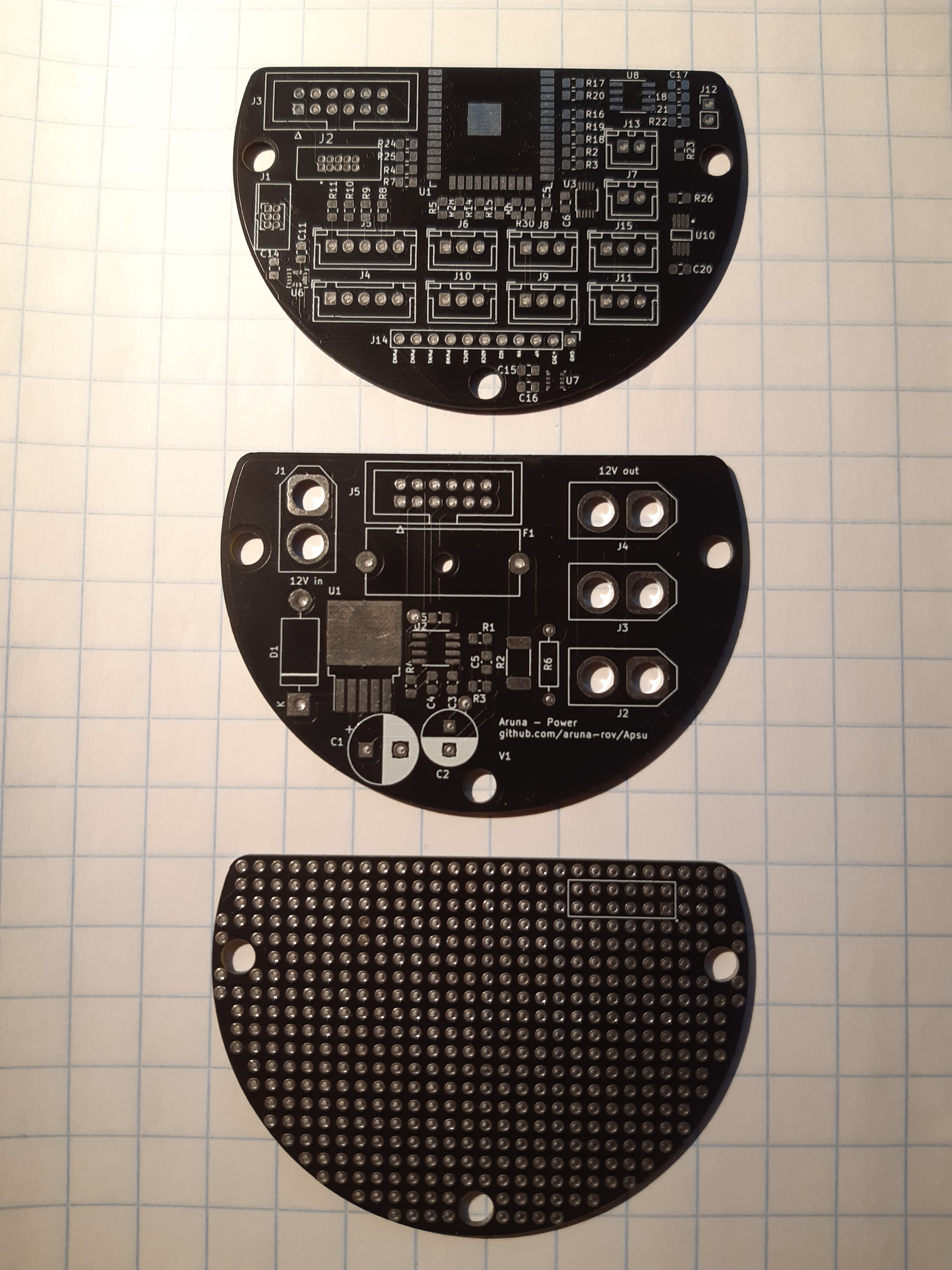
I took a bit longer then I originally anticipated but I have finally received my PCB’s! The main reason it took so long was because I made some mistakes in the power board, I totally forgot to accumulate the characteristics of a capacitor at certain frequencies. But after reading my eyes dry at datasheets I managed to pick the proper parts and redesigned the layout a bit so it would all fit.
![]()
Top to bottom: Apsu board, power board, prototype board ![]()
completely soldered Apsu board ![]()
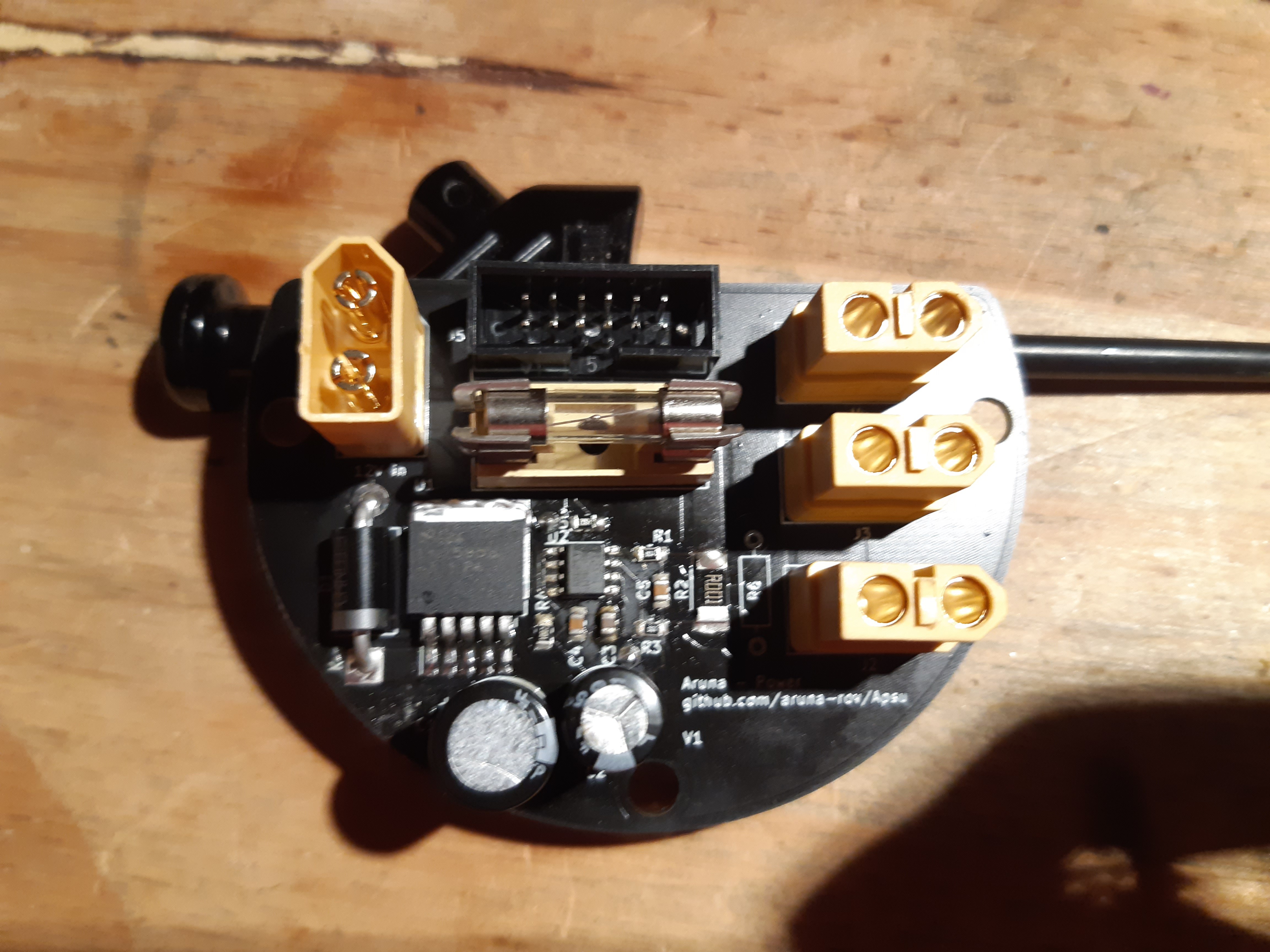
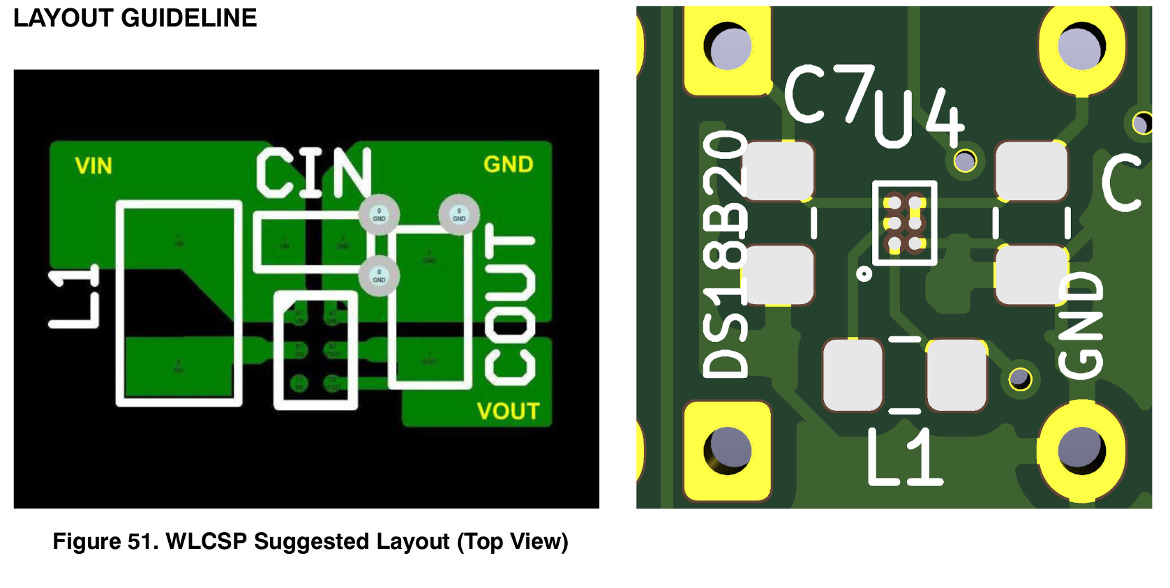
completely soldered power board (black stick is just to hold it upright for the picture because there is a big inductor on the back) The three boards came out fine, the black matches with the rest of the ROV so it all looks pretty nice so far. This was my first experience with SMD soldering with a hot air reflow station (bought especially for this job) but non the less the soldering process went smooth, and there were little complications. During soldering, I noticed one big flaw in the main Apsu board through. “U4”, the boost converter on the back of board was mirrored. So I could not install the chip, pretty stupid mistake and I’m not sure how I managed it. I do recall a mental note on orientation of the IC but I missed it during checks regardless.
![]()
Right: FAN4860 layout refrence, left: Apsu mirrored footprint Testing
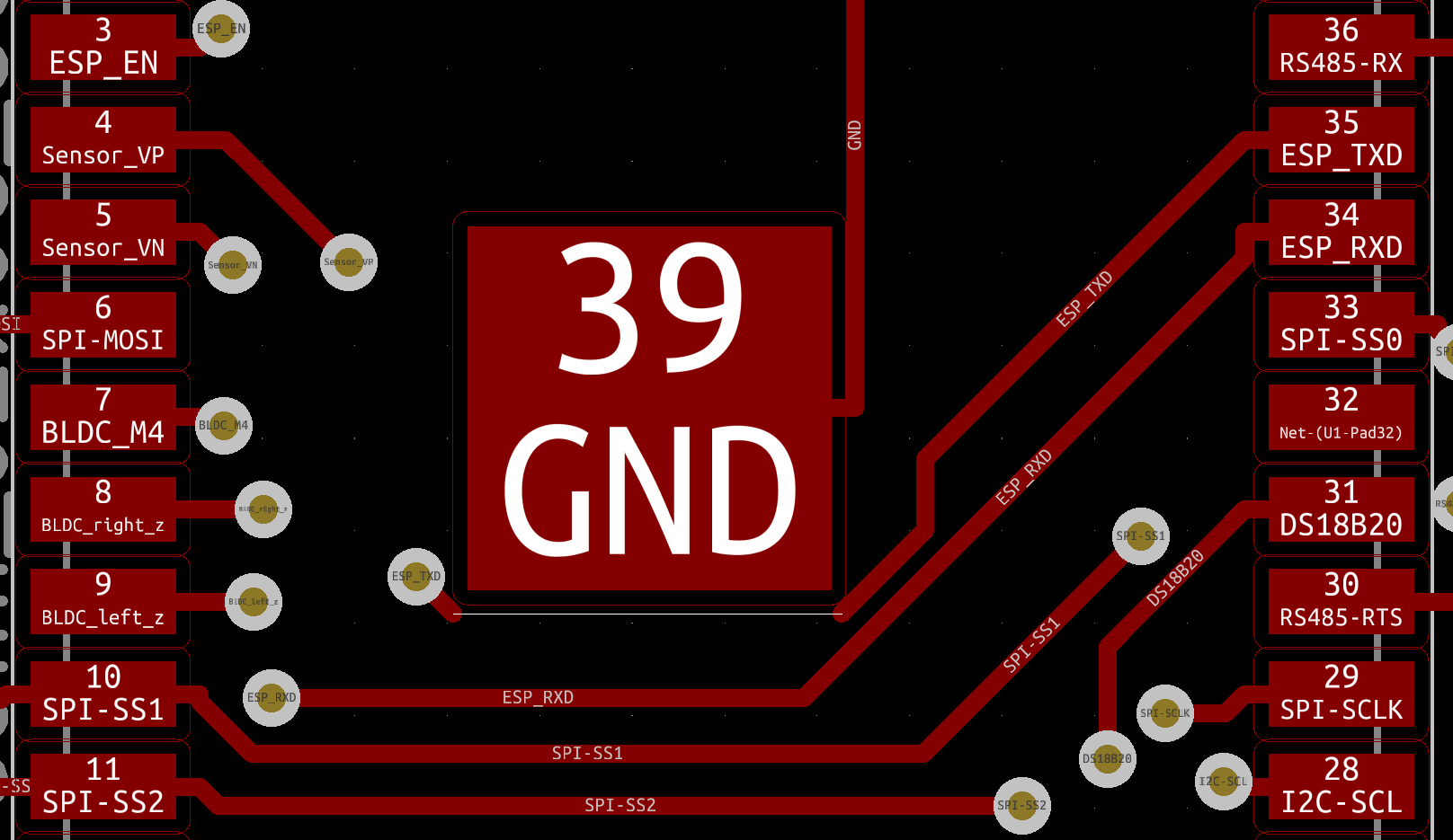
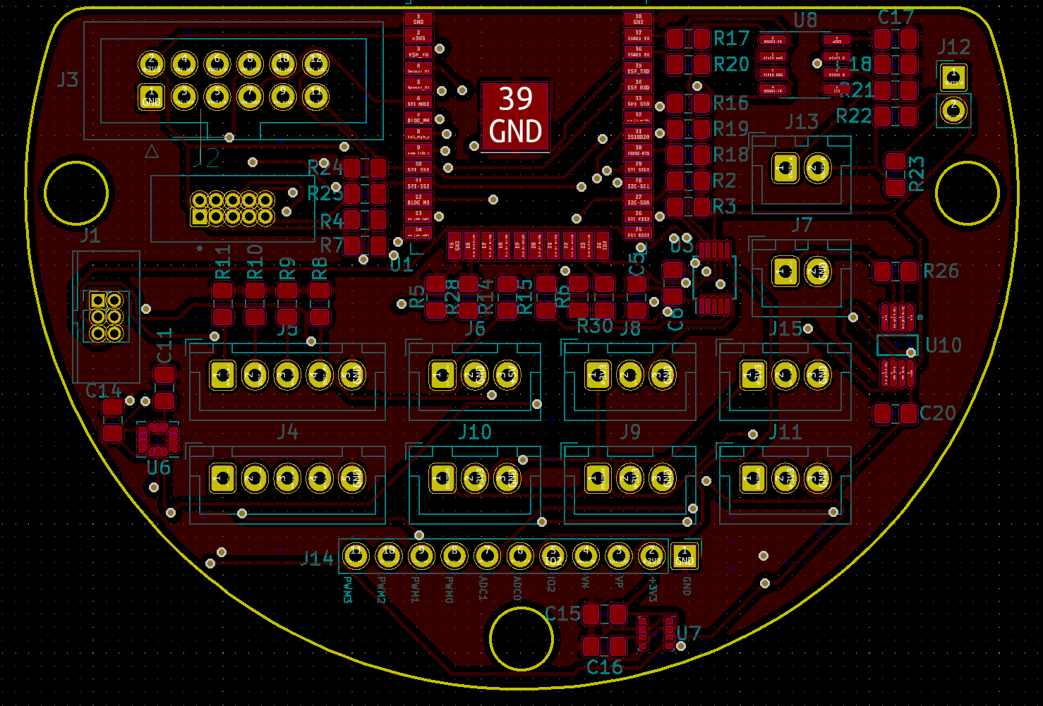
This is the moment of pay-off or regret. Whenever the months of research, designing and spending just short of 100 Euro on supplies was worth it. I first tried talking to the ESP32 module via JTAG and UART, JTAG worked fine and after flashing a hello world example program I was not receiving any data from the device. Stepping through the code using GDB showed that the code was indeed being executed but was somehow not getting to my computer. It turned out that the Tx track going under the ESP was missing from the PCB :(… Pretty big blunder if you ask me. Luckily I have learned from my mistake and will hopefully not make it again. I think it happened right after I was working on re-routing the Tx track and I then wanted to delete something while the Tx trace was still selected. Normally this would have been caught by the DRC check but that was giving so many false positives that I decided to ignore the whole report, haha. Soldering a wire to the two terminals fixed the issue, but the board does not look as elegant as it did before.
![]()
Notice the broken "35 ESP_TXD" trace under the "39 GND" The power board produced a clear 3.3V signal so all my redesign work was worth it :), have not yet tested the volt/current sensor.
The MAX485 for RS-485 communication works, this was expected because I already created a failed attempt at a USB to RS-485 converter. So I learned from my mistakes. ADS1015 for 12 bit ADC through I²C works fine. And I’m currently in the process of creating a driver for it. The next IC I will test will be the PWM controller.
![]()
My current test setup with a logic analyser and FT2232H at my side -
Three PCB boards
07/11/2020 at 06:27 • 0 commentsApsu PCB Design
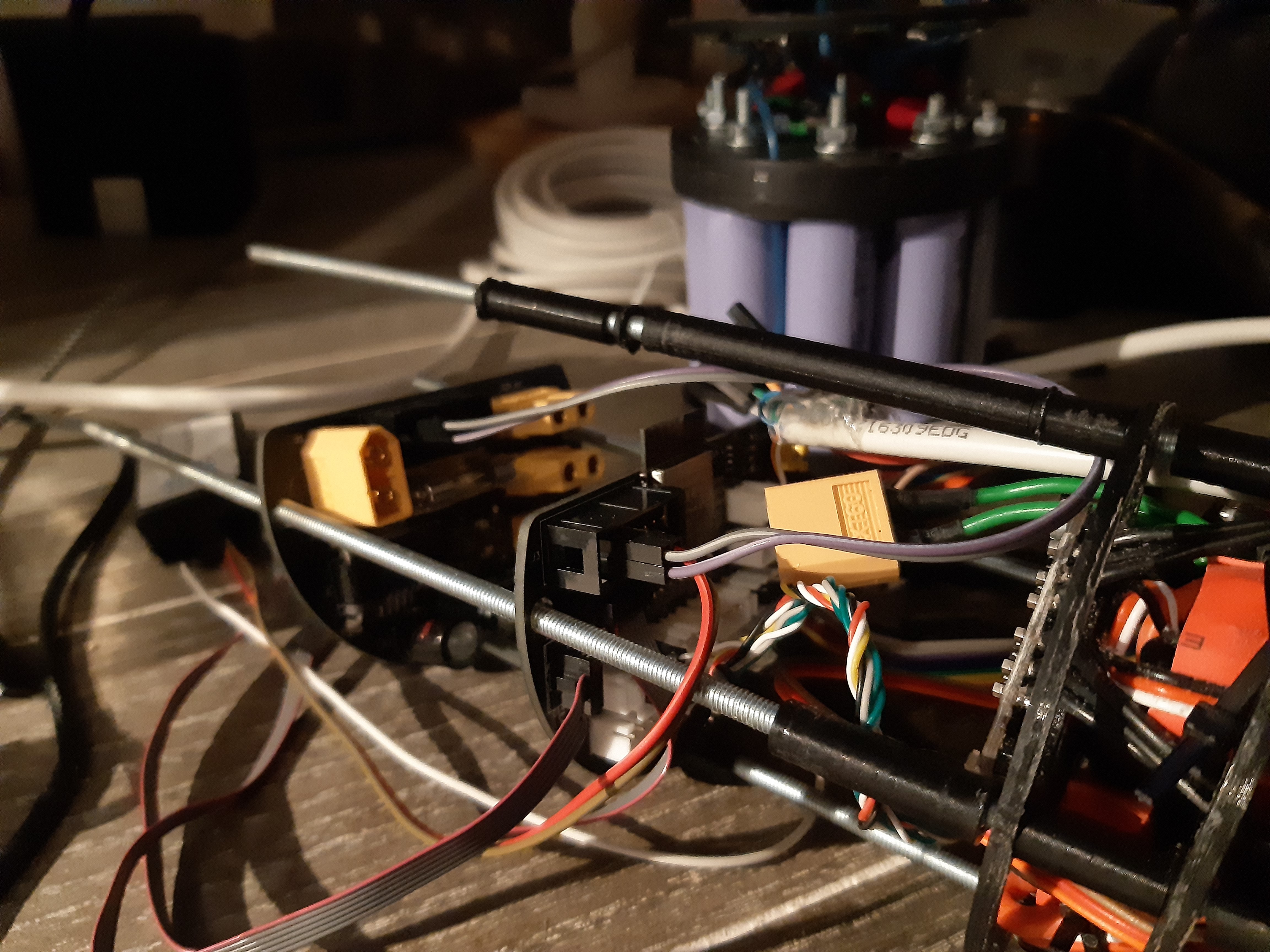
Since the beginning of the project I wanted to create a PCB that houses the electronics of the project. This was later further motivated by the big rats nest and space limitations of the prototype board I was using. Some wires kept going out mid dive duo to the 2.54mm pin-headers not being really movement friendly.
![]()
Current prototype board wiring I also wanted to add extra sensors for finer movement control of the ROV. Because currently the device is blind and deaf to its surroundings. So it is required to do all the steering, calibrations and adjustments manually. I choice to fix it in my next iteration of the project by designing a PCB with the follow features:
- ESP32
- Inertial Measurement Units (IMU) (compass, gyroscope and accelerator meter)
- JTAG and UART debug ports
- expansion port for future additions
- RS485
- on-PCB temperate measurement
- water t temperate measurement
- battery and ESC temperate
- Humidity sensor
- outside pressure sensor
- inside pressure sensor
- BLHeli motor driver
- SimonK (PWM) motor driver
- 2xwaterlevel measurement
For all things concerning power I decided to create a separate PCB with:
- battery voltage measurement
- complete circuit current measurement
- XT60 breakdown
- 12V to 3.3V step-down
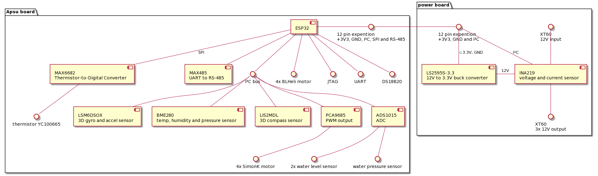
Here is a complete block diagram breakdown of the two PCB:
![]()
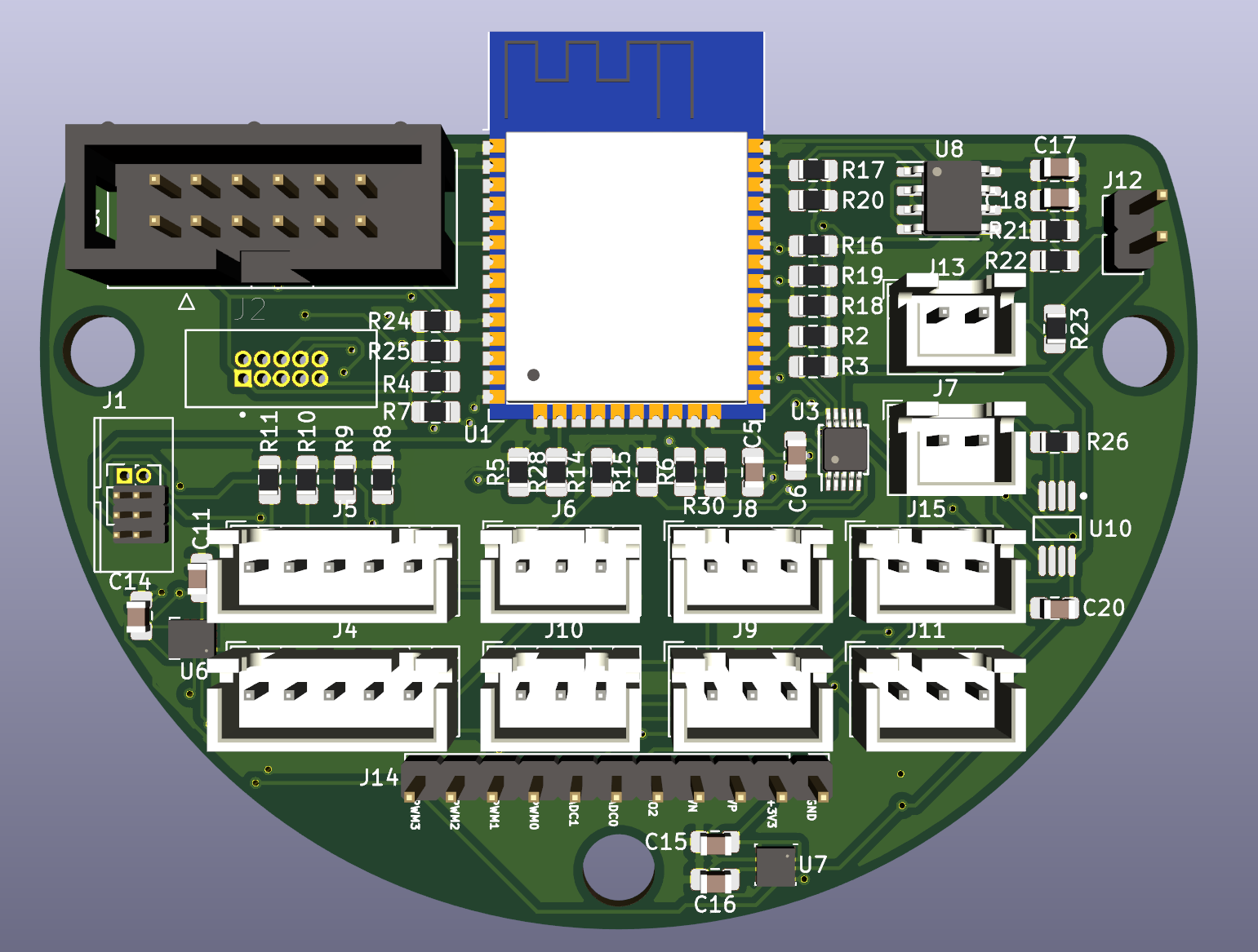
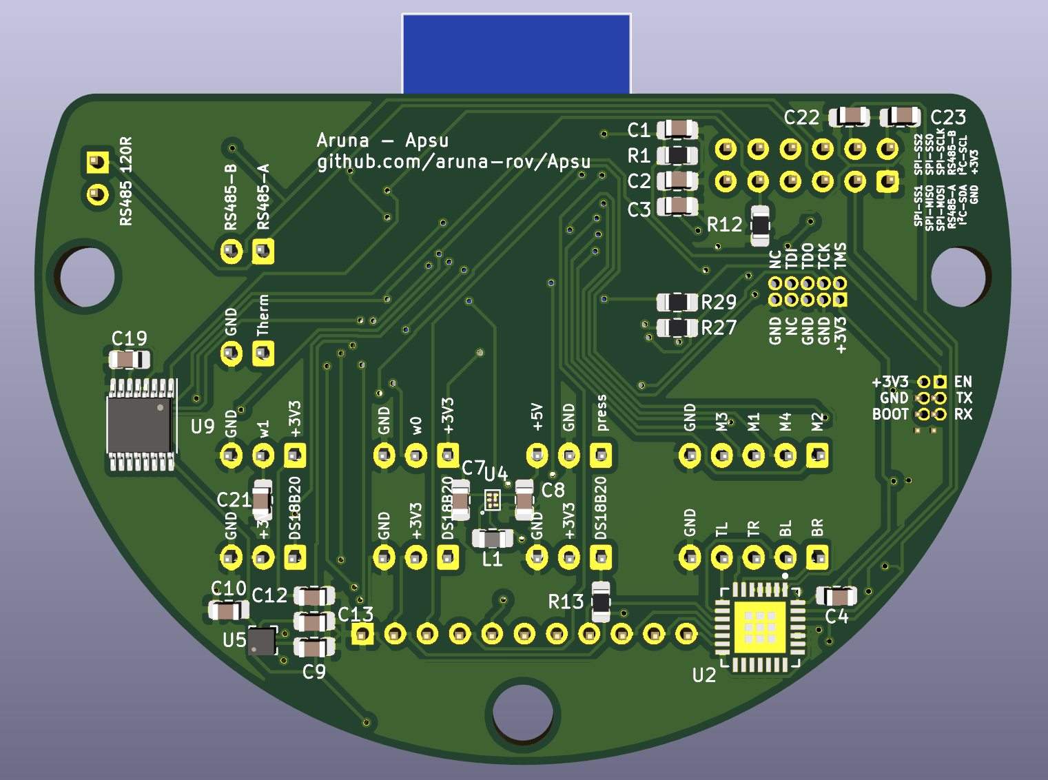
Block diagram of Apsu and power board Apsu board
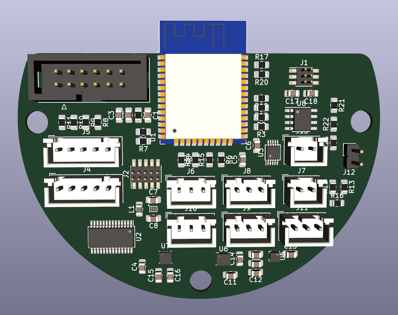
![]()
Apsu board front 3D I originally wanted to create the board with a naked ESP32D (U1) chip, without the shell that contain the flash and a crystal and such. But I got intimidated by the data-sheet and the complexity that the ESP32 requires to operate. So as inexperience as I am, I decided to go with the ready to use ESP32-WROOM.
The IMU sensors are formed by an LSM6DOX (U6) made by IT controlled over I²C for 3D accelerometer and 3D gyroscope. The compass is also from ST; the LIS2MDL (U5) also controlled with I²C. Picking these chips was no easy task as I originally wanted to have the boards fully hand soldered. But IMU-type chips are rarely that big, so I instead went with the highest accuracy/price combination that was also highly available and well known to make it easier to write drivers for.
JTAG capabilities are of course an absolute must, especially since I have not yet created drivers for 90% of the IC’s attached to the ESP32. 1.27mm pin header (J2) where chosen because big 2.54mm simply would not fit.
![]()
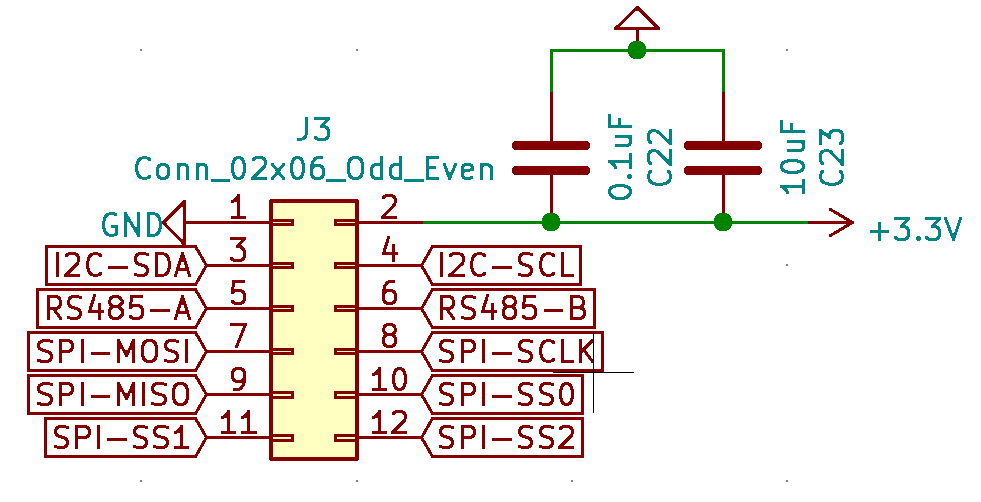
Expansion port To keep the project modular I designed an expansion port that can daisy chain to as many boards as you want.
- GND and +3V3 to supply (and get) power to other boards
- I²C/SPI for peripheral master-slave communication
- RS485 for master-master communication
- SPI_SS0-2 for Slave-select, total of eight SPI slaves are supported. `0b0` is standard selected and `0b1` is in-use for the pressure sensor
RS485 is brought by a MAX485 (U8) chip, uses J13 for outboard A and B. short J12 if it's the end node to connect the 120Ohm resistor between A and B.
Temperature, Humidity and in-hull pressure is all measured by a BME280 (U7) by Bosh, communication over I²C. The humidity and in-hull pressure are used to detect hull breaches. Because the air pressure will rise when the hull is breached and the humidity will also rise. Having multiple redundant ways of measuring something critical as a hull breach is important as it increases safety of the device.
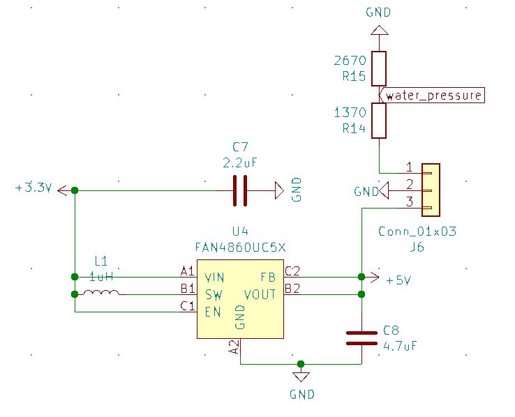
The water-pressure outside the ROV is measured using the cheapest water-proof pressure sensor I could find: “EBOWAN DC 5V G1/4 Pressure Transducer 1.2 Mpa” with the ¼ A4 of documentation available on Aliexpress it is just enough to drive it (hopefully). Unfortunately this sensor requires 5V, while all my other components are on +3V3. So I have made a 3-5V boost converter specially for this sensor (FAN3860 (U4)). Together with a voltage divider to read the analogue output of the device.
![]()
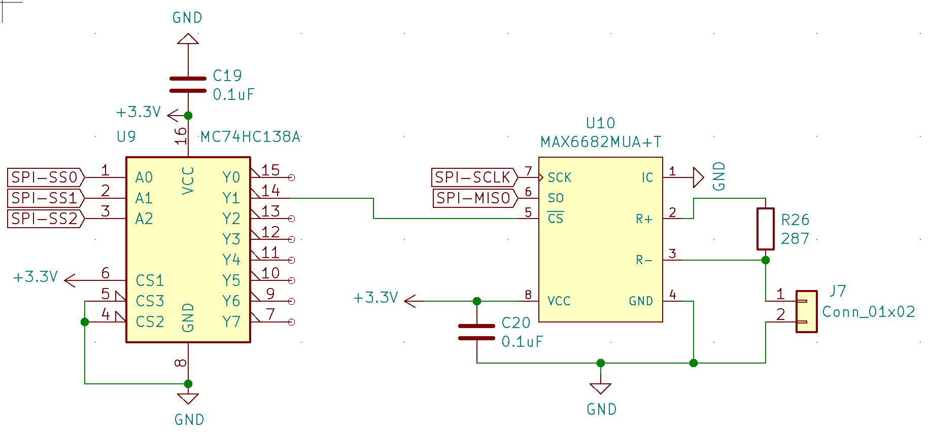
water pressure sensor schematic The water temperature is measured by an even undocumented sensor as the pressure sensor. The YC100665 a thermistor connected to J7. The thermistor is measured by a MAX6682 (U10) to fix self-heating and filtering for the thermistor. Communication is done with SPI and using a MC74HC (U9) for Slave-select multiplexing.
![]()
Thermistor schematic The temperature of the battery, ESC’s and possible something else in the future is being measured by DS18B20 (J9-11) sensors.
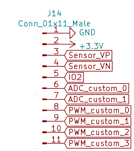
The BLHeli motors (capacity of 4) will be connected to J5. The SimonK motors are operated through an PCA9685 (U2) I²C to PWM. Four motors can be connected through J4 and another 4 with the 2.54mm pin header (J14).
The water level is measured using a ADS1015 (U3) I²C ADC. The water level sensors are connected to J15 and J8.
This is still a development board, so extra things may be connected with pin header J14. That functions as a breakdown board for unused, but useful features of the IC’s on this board.
![]()
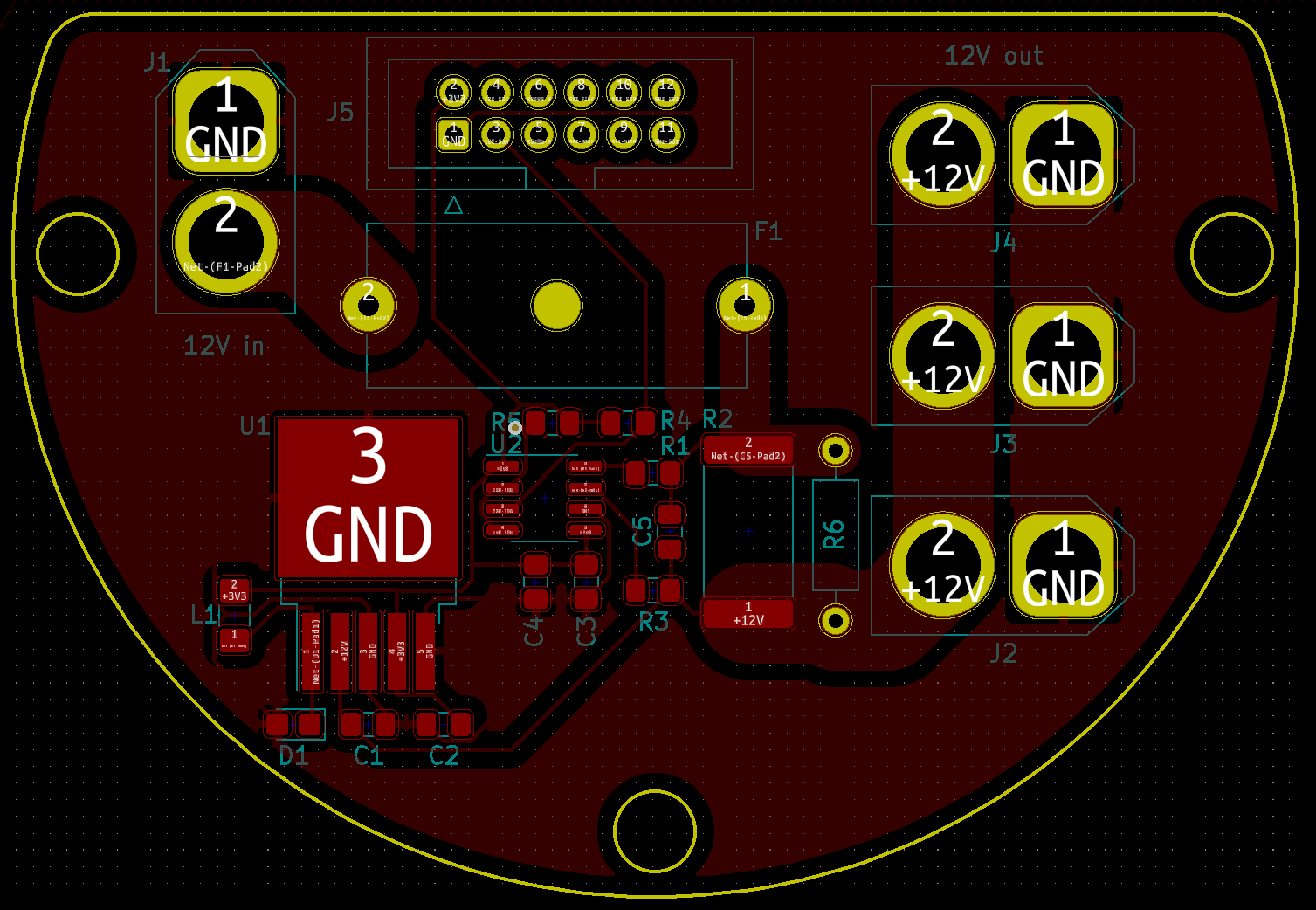
Breakdown header Power board
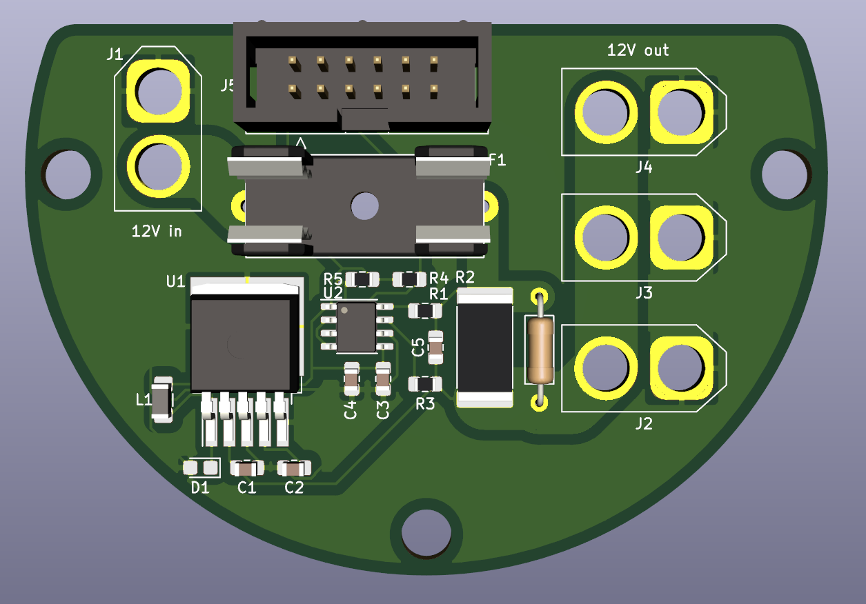
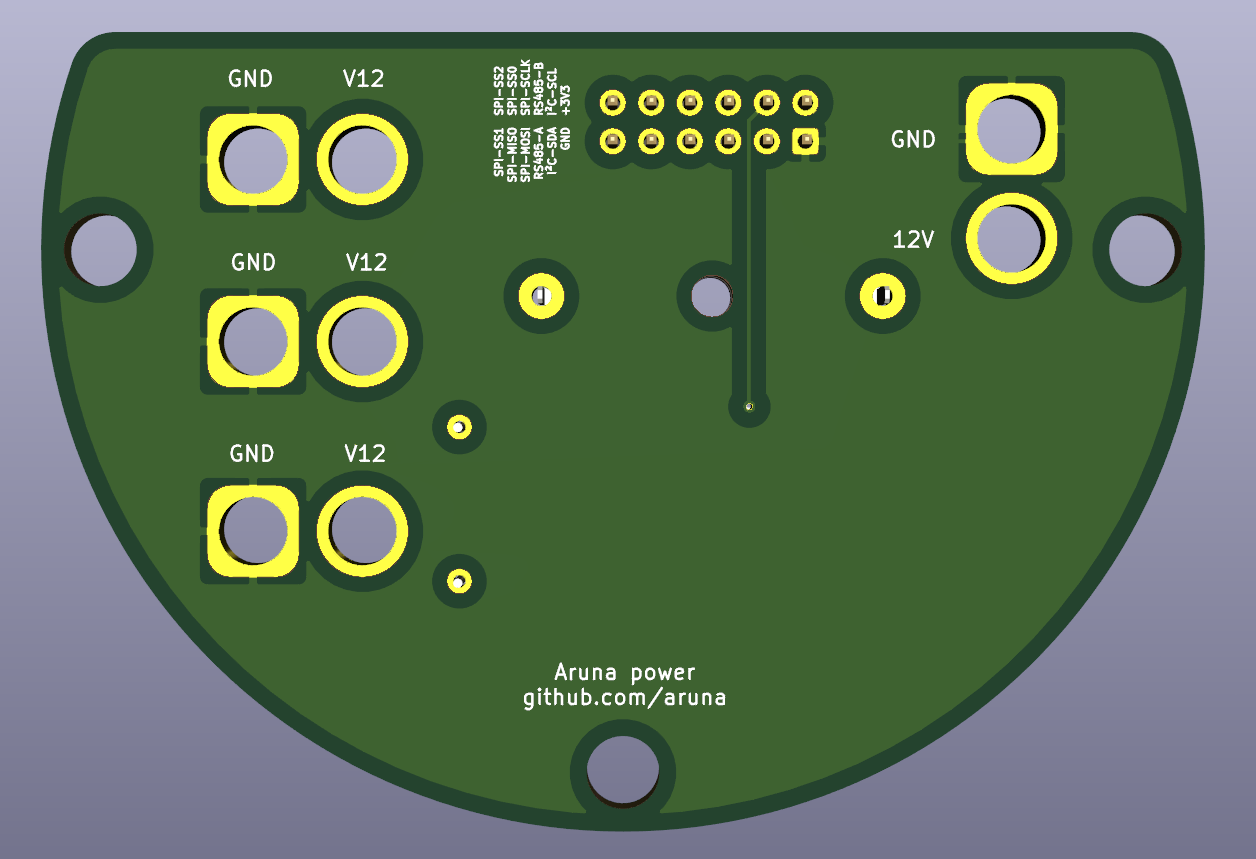
![]()
power board front 3D Next to the main Apsu board I also developed a board to manage the power of the ROV. This boards converts 12V into 3.3V and monitors the voltage and current levels. The power comes in though XT60 connector J1 it then follows it way though a fuse, and is fed to J2-4. A LM25955-3.3 (U1) is used to convert 12v to 3.3v. And send on the bus using J5 with the same layout as the Apsu board. The current and voltage is measured using an INA2918A (U2) this sensor communicated the result back to the main board using I²C.
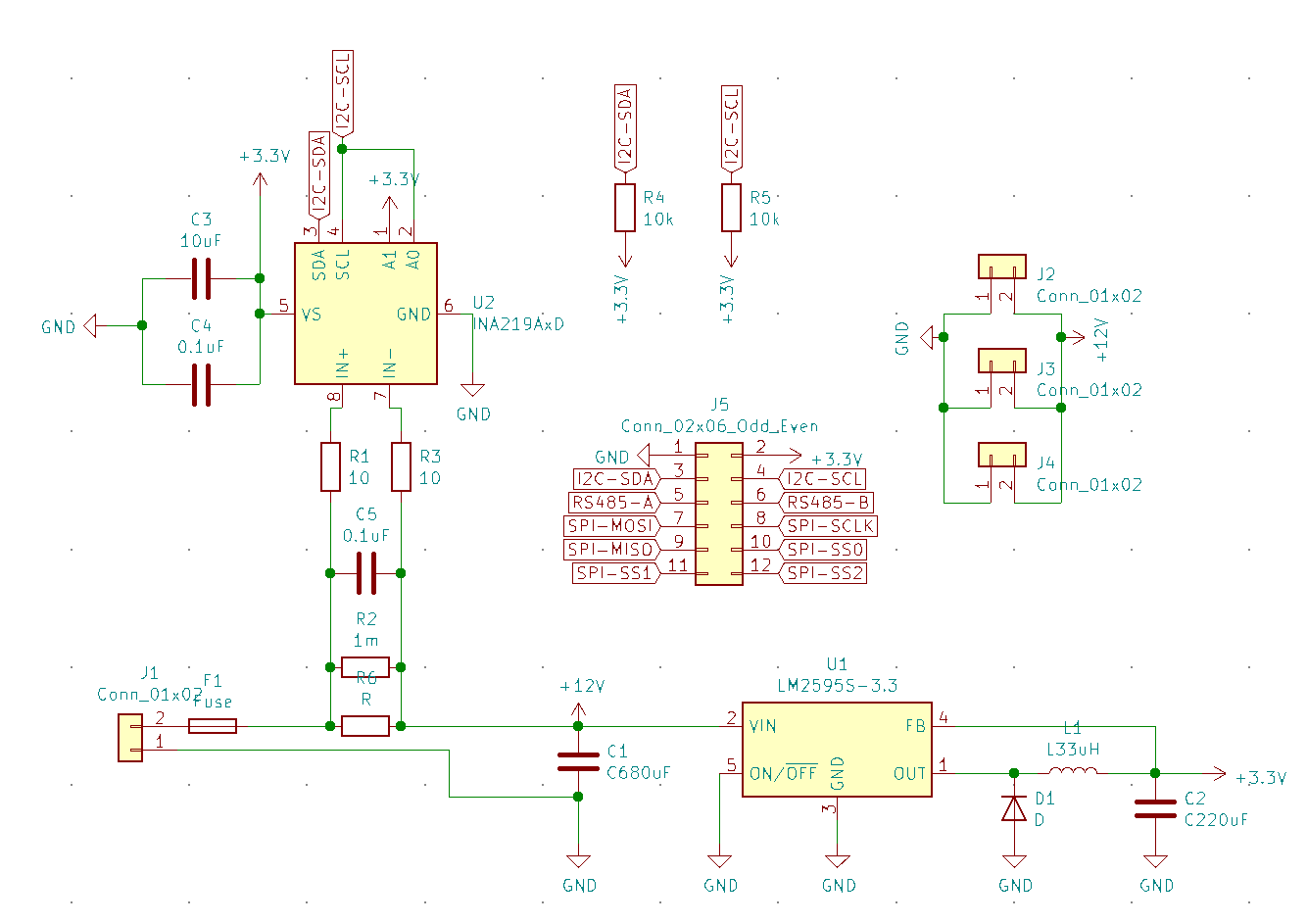
![]()
Power board schematic Prototype board
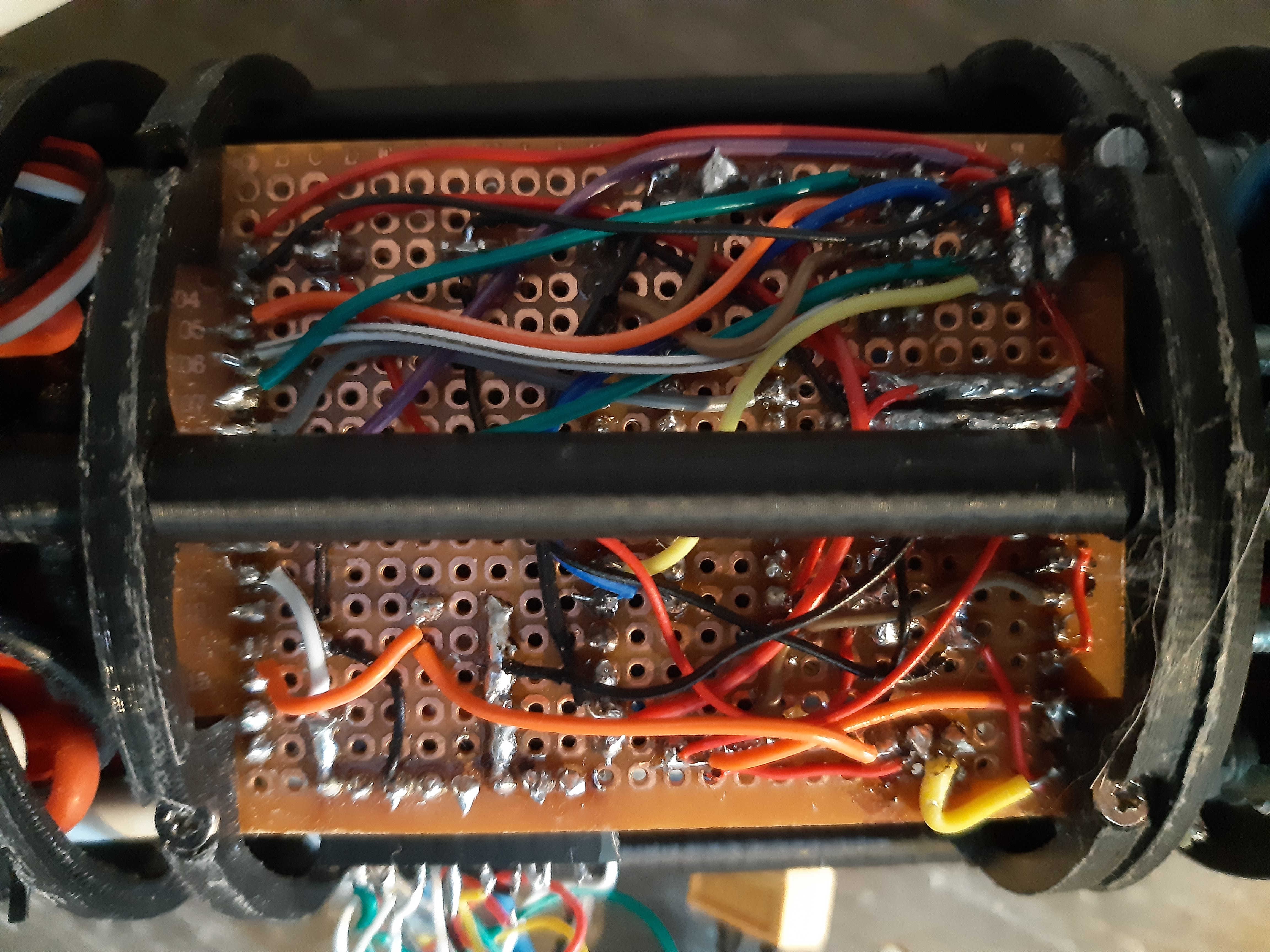
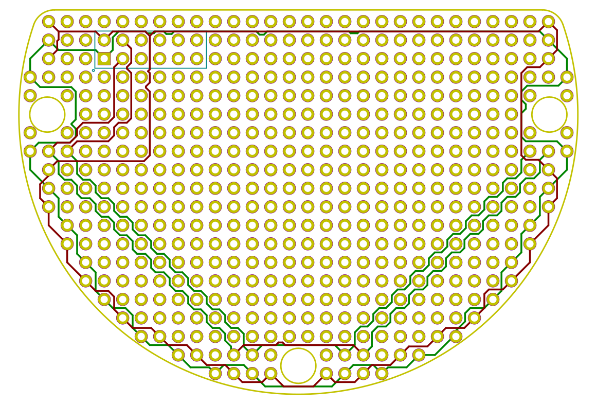
![]()
prototype board As shown in the top picture it can be quite a hazard to create prototypes in the tight space of a ROV. So for future prototyping I thought it would be nice to have a prototype boards that fits exactly in the ROV and already distributes the most commonly used pins on the bus: GND, +3V3 and I²C.
Some more images
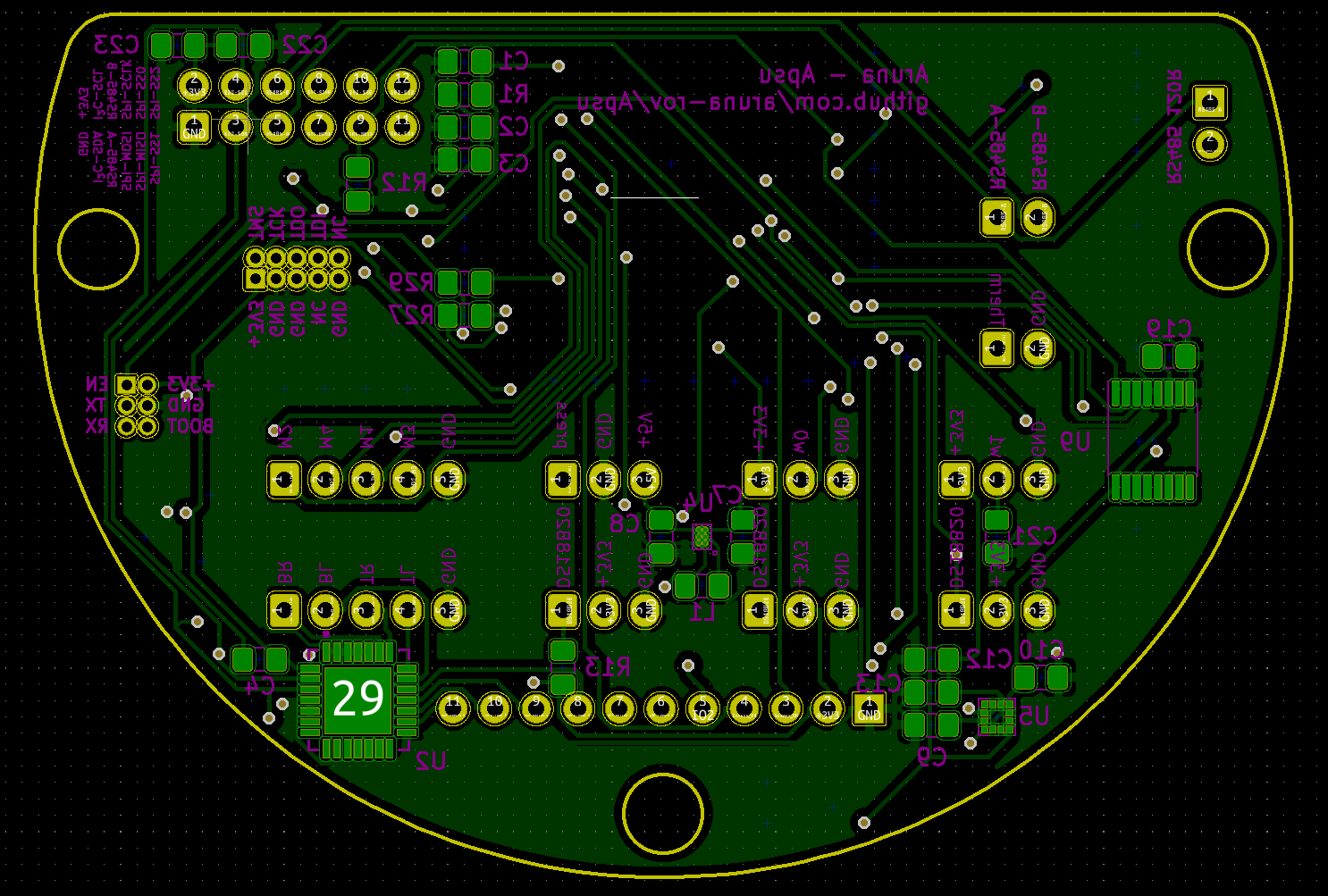
Apsu board:
![]()
Apsu front ![]()
Apsu back ![]()
Apsu back 3D
Power board![]()
power front ![]()
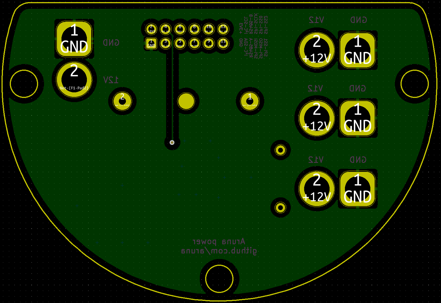
Power back 3D ![]()
power back -
PCB sneak peek and wire documentation
06/24/2020 at 15:13 • 0 commentsPCB sneak peek
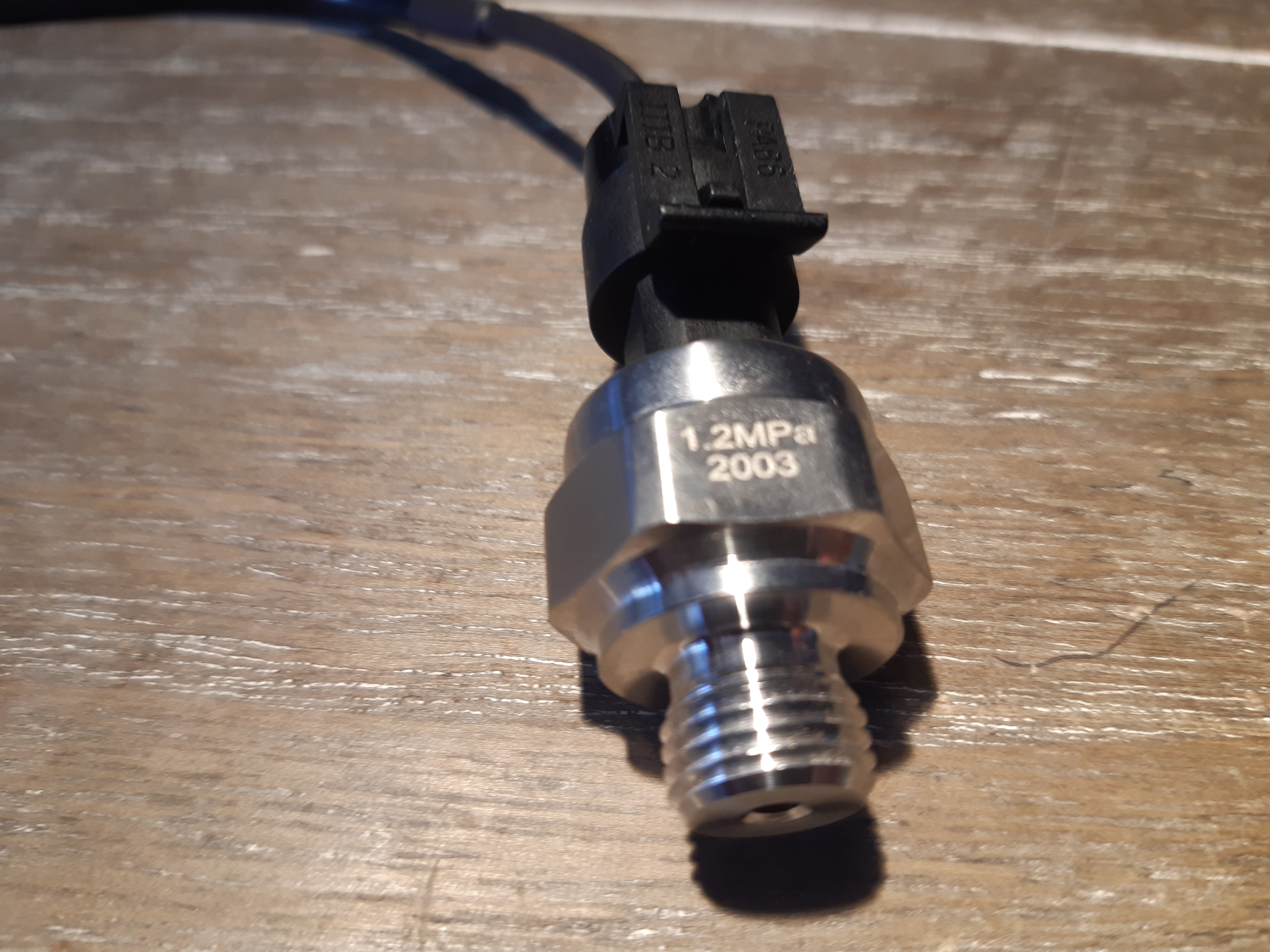
For the last few weeks I have been hard at work at designing a PCB for the ROV. It will include the base ESP32 module as is, plus a ton of extra sensors and connectors for much more sensors! One of these new sensors is an underwater pressure sensor that I got today.
![]()
Furthermore, here is a little sneak peek of the PCB (not yet finished):
![]()
Wiring documentation
There is a lot of cabling in the project. It can be quite complicated and it is easy to make mistakes or to forget to plug a wire back in when they become disconnected. This will only continue to grow with the project. So I create a document of all the wires and how they connect to each other.
![]()
Made with https://github.com/formatc1702/WireViz
Aruna - ROV
Modular ROV for underwater exploration, discovery and monitoring