I missed a critical requirement. There's a lot of great assistive tech out there that works really well, but boy does it look clinical, boring, medical-- just not exciting. Whatever I make here must be exciting and engaging. Part of that is color-- with 3D printing, there's a rainbow of choices. You can make switches with the colors of your favorite team. You can pick vibrant colors that grab attention. You could make a pile of different switches so you can always match the color of your shoes or the ribbons in your hair.
We need switches with lots of different designs. Different textures. Different personality.
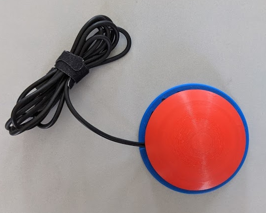
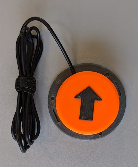
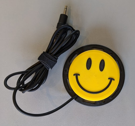
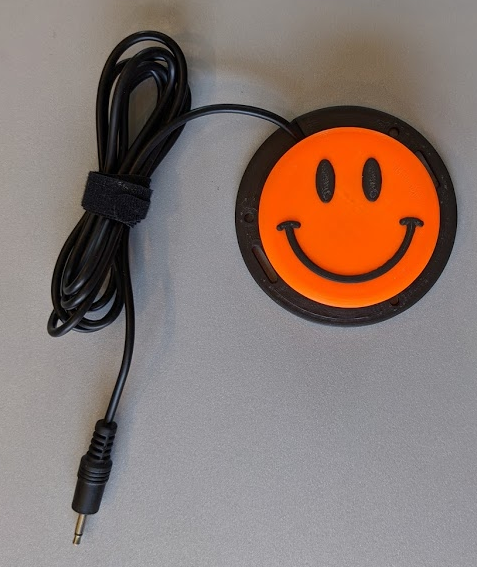
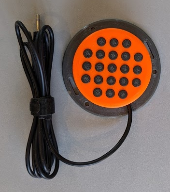
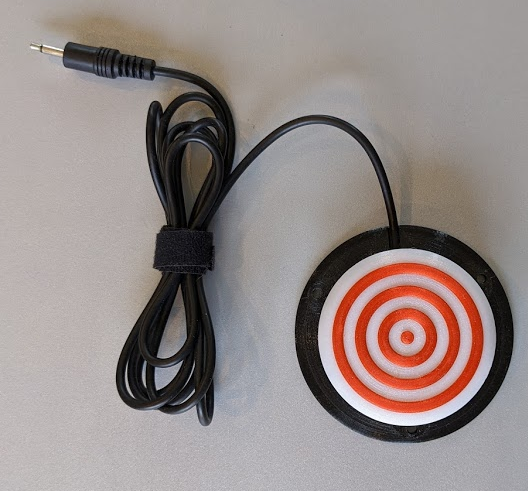
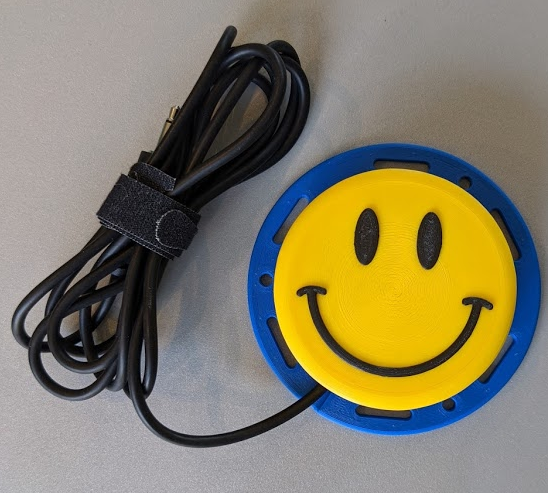
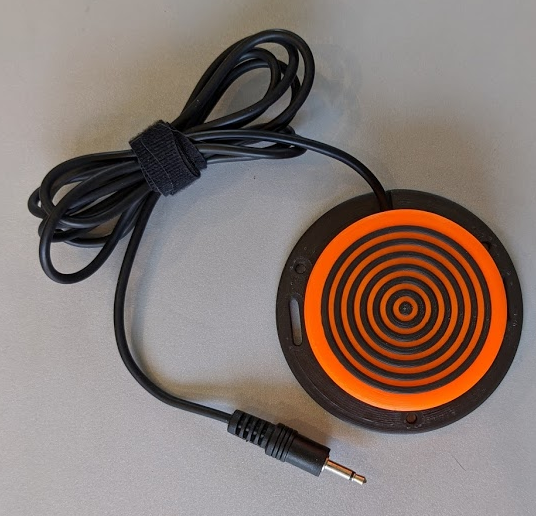
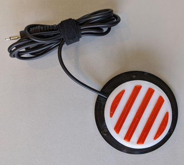
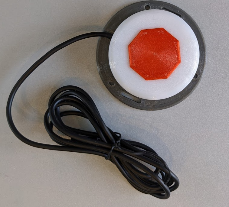
Here's a selection of some of the designs in a variety of colors. All built on the same basic Interact Switch platform.
I've created a bunch of different designs-- and others are free to make plenty more. The sky is truly the limit. Additionally, the varied textures are valuable for those with vision impairments-- or even just to provide a tactile association between a switch and its action.
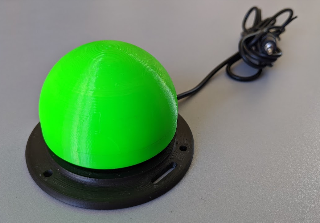
One of my original requirements was that the switch be easily triggered by hitting it on the side. While the existing flat switches do still work if you hit them on the side, it seems like we can do better. If the switch cap is a dome, then any force hitting it on the side would still result in a downward force. Here's my first iteration of such a design.
This first attempt was a bit of a failure. It is basically a hemisphere on top of the existing switch. There are two main issues here. First, there are still flat sides, and those aren't great. The other issue was a bit of a surprise to me. This design has a lot of infill, making the switch cap much heavier. As a result, on rare occasions, the switch will stay depressed even when you stop pushing it. From a usability standpoint, that's a huge problem. Back to the drawing board.
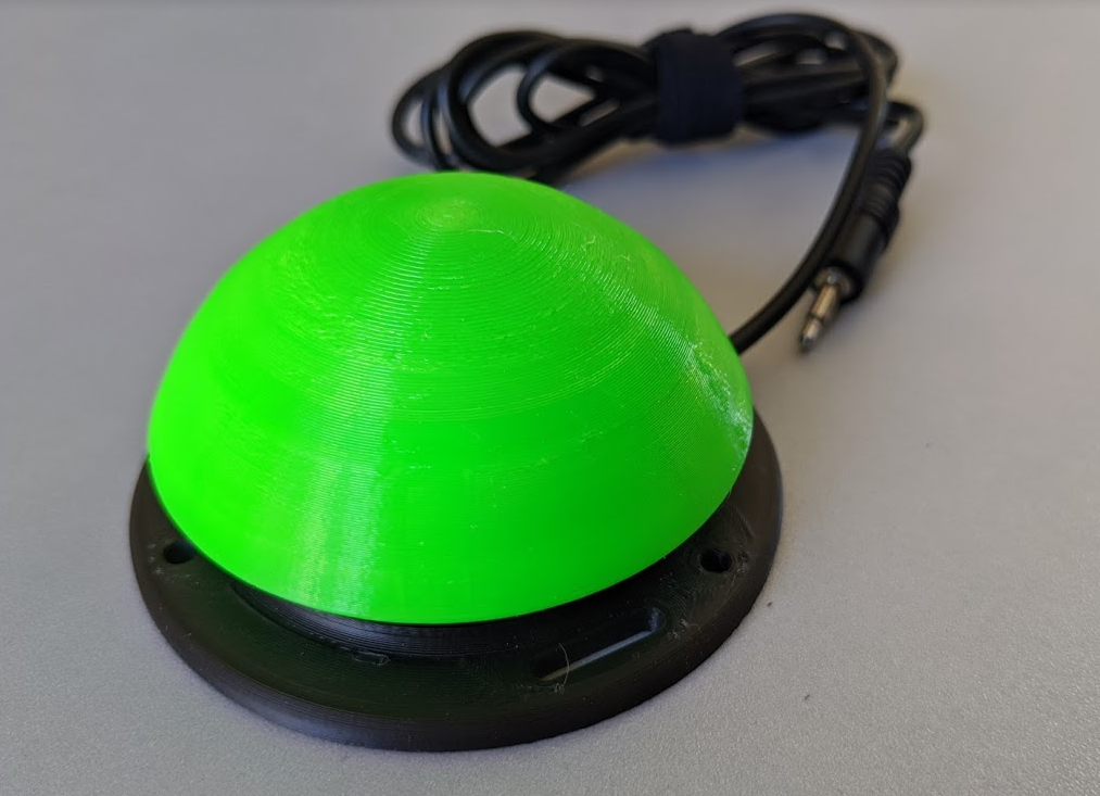
And here's the redesign:
This fixes both issues with the "hemisphere" design above. Most of this switch is just a 2mm thick shell, so there's little added weight. And the design is smoothly curved, but even out to the edges there is a substantial slope, so it's exceptionally easy to depress, even with a completely lateral movement.
I think it's also worth taking a moment to look back at the original goals. There is no single switch that could ever be the one design that's best for everyone. For example, the flat switch is a better design for using as a headrest-mounted switch because it's more comfortable to push than the dome. But the dome is probably better when on a tray or table, as it requires less precision to activate. When identifying the right assistive technology for a given situation, you've got to be fluid with your assumptions and willing to try, fail and try again to find what will work best. In that vein, this project is not trying to come up with "the perfect switch." It doesn't exist. What I hope to accomplish is to put out a set of different designs, for various affordable switches that will hopefully meet a the needs of a wide array of users and be equal or superior to what you can buy right now for a burdensome amount of money.
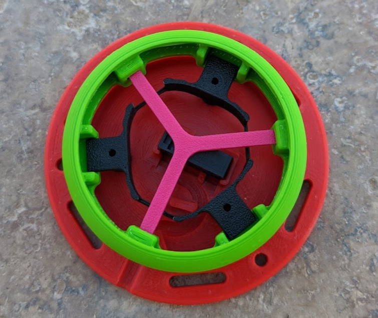
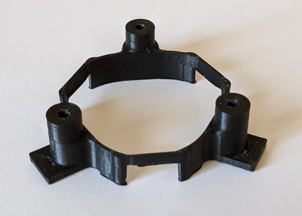
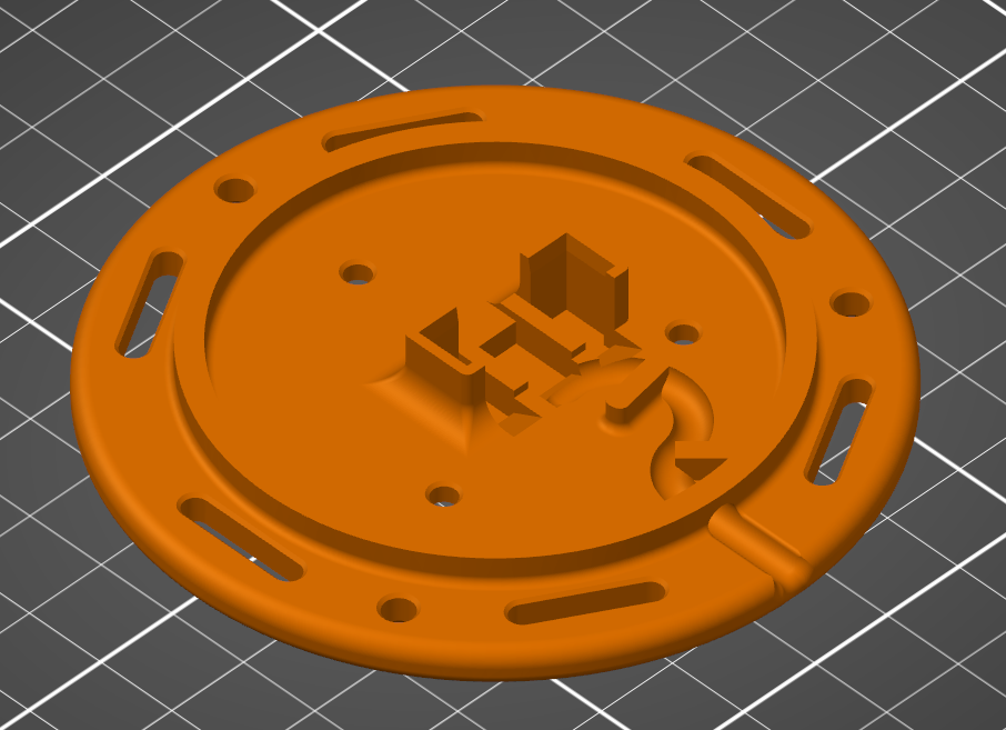
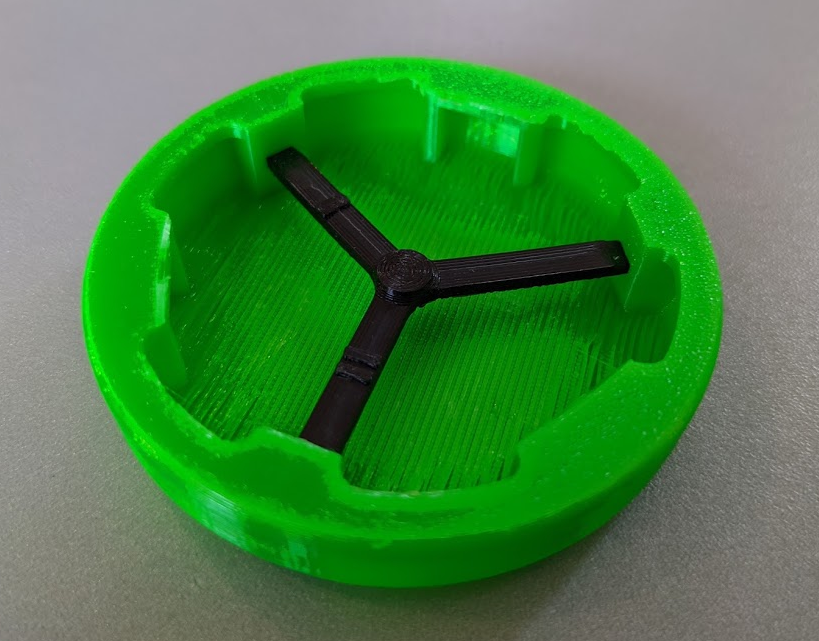
It can be hard to visualize how the various parts come together to form a working switch. I made the following mockup to help visualize how the precise interaction of the parts and troubleshoot issues.
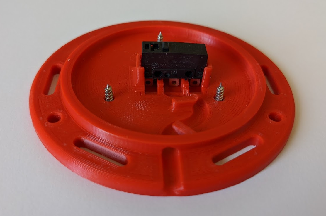
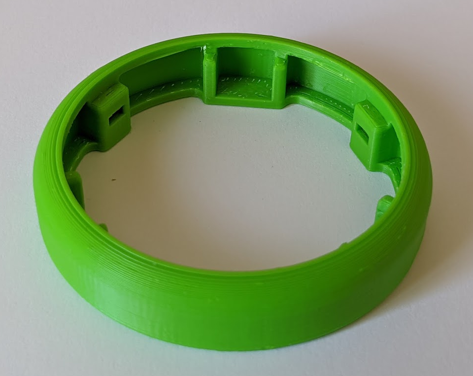
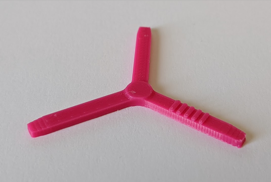
Here, you can see the Omron SS-3GP switch in its cradle (with no wires attached). The black "cap holder" is screwed down to the red base. It's easy here to see how the black "switch holder" keeps the green "switch cap" from falling off or rotating, but does so with minimal friction. The green "switch cap" is missing its top, allowing us to see in. And the pink "switch insert" inserts into three holes in the switch cap, and depresses the switch.
We've discussed tolerances some before, and this picture makes it much easier to see how the design minimizes and mitigates the effects variation in part dimensions.
In order for this switch to perform well, the height of the pink "switch insert" must be precisely controlled to within about 0.1mm to 0.2mm. And we have to reliably hit that when some of these parts with layer heights of 0.2mm.
Minimize Variations
First, to minimize the variations, it's important to consider how a 3D printer manufactures a part. First, it lays down an initial layer, generally smooshing that first layer into the print bed. The print bed itself will also have slight variations. Combined, this means that the first layer (or maybe even first few layers) of a part can be expected to have fairly high variation in thickness.
Another place where you'll see a lot of variation is in overhangs. There will be some drooping in overhangs, and the amount of drooping can vary with temperature, filament, printer, speed, cooling, support, etc.
Where we can find reliable, precise tolerances is between horizontal "top" surfaces on a part. Let's look at the "cap holder" for example. It is printed upside down, and the critical dimension (where it mates with other parts) is on two "top" surfaces.
With the red base, the critical dimension is on the top surface-- where the cap holder feed reside and where the SS-3GP microswitch sits.
With the green "switch cap," the critical dimension is the top surface that mates with the cap holder, and the pockets that hold the pink "switch insert." The pockets have both a "top" surface and an overhang. The variance in the overhang is largely suppressed because of another trait of the overhangs: they're a bit soft and sponge-like. The pink "switch insert" has a slight wedge to it, and the softer overhang helps to press the "switch insert" flush against the top surface of the pocket.
That leaves the switch insert, which is also printed upside down. That means that its top surface is being pushed against the top surface of the pocket on the green switch cap. The other critical surface is where the "switch insert" presses against the microswitch. Again, this is a top surface when printed, and so has high precision.
Of course, the last piece in all of this is the Omron SS-3GP switch itself. And it's safe to say that all of its tolerances are significantly better than the 3D printed parts.
Mitigate Variations
Now that we've done all we can to minimize variations, we now have to accept the fact that nothing is perfect and we'll have some variation and have to handle it somehow.
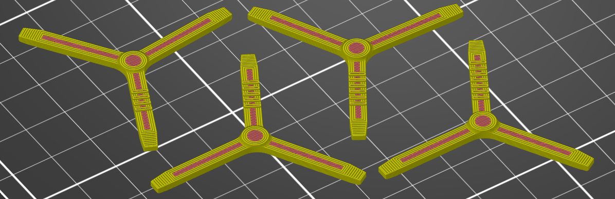
Early in the design process, I knew that I wanted the ability to have a small, quick-to-print component that would be easy to replace that could be used to "shim" to adjust for variations in tolerances. That's where the "switch insert" comes from. Each switch insert takes less than 10 minutes to print, can easily be swapped out, and can be printed with different thicknesses in 0.1mm increments.
Above, you can see 4 different inserts, where the center "nub" has a height ranging from 0.4mm on the left to 0.7mm on the right. In order to identify the height of a given insert, I have added stripes to the model that indicate which variant a given part is (you'll see 4 stripes on the left insert, up to 7 stripes on the left insert).
The Results
I've been surprised at how well this has worked. Of the first 50 or so switches I've printed, every single one has required the 0.6mm switch insert. When I developed a different style of switch cap (I'll talk more about it in another log), I found that I always had to use a 0.5mm insert for it (again, for every one I printed), even though the critical measurements for it shouldn't have changed between the two cap designs. This tells me that the random error is effectively negligible, and the systematic error is highly repeatable. This is fantastic, as it makes manufacturing a large batch much easier/ faster. You effectively don't have to worry about disassembling switches to swap out with a different insert, which would be rather time consuming.
I've been wanting to quantify the "feel" of a switch for a while now. The best way I have been able to come up with it to measure the force vs. deflection curve. In this update, I'll present the data for several different switches.
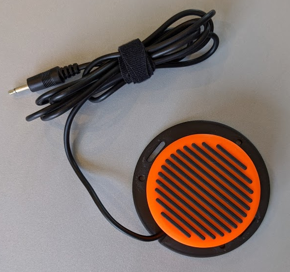
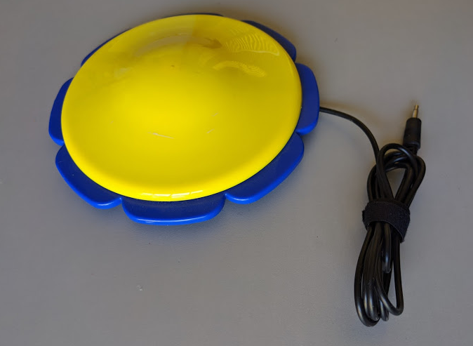
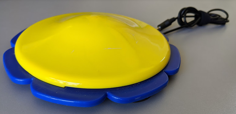
The first switch tested is this Scallop Switch. It's a large switch sold by the nonprofit American Printing House for the Blind. It's a very functional switch at a price point that's unmatched. (They also have a great wobble switch that I also highly recommend.)
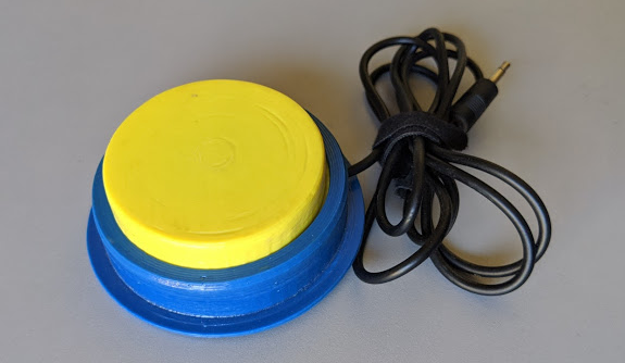
The next switch I tested, I'm calling a "clunky" switch. This is one of my early designs, and while it is functional, it just feels clunky to use. I was really interested to see how this would compare to the other switches.
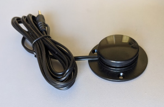
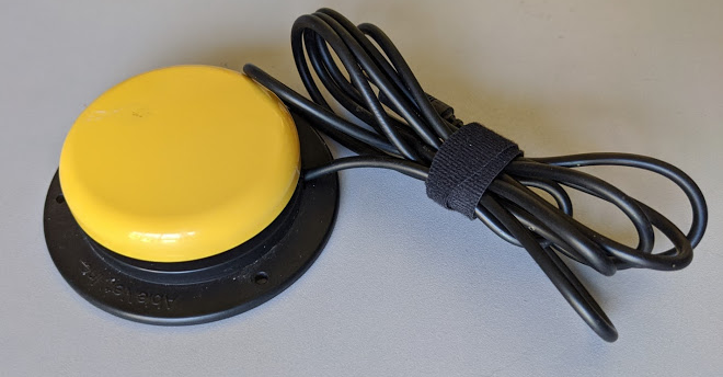
Next up is the Specs Switch. This is a popular small switch. It has a short throw and is manufactured by Ablenet.
We also have the Jelly Bean switch, also by Ablenet. This is a very widely used, popular switch. It's a great medium size and can be used in a lot of different situations.
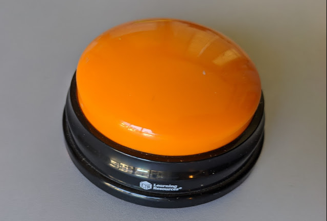
This next switch is not an adaptive switch at all, but rather it's a switch that makes one of various noises when hit. They're sold in a pack of 4 for about $15. I included it here because I see a lot of people converting this into an adaptive switch (you can find a bunch on Etsy, for example).
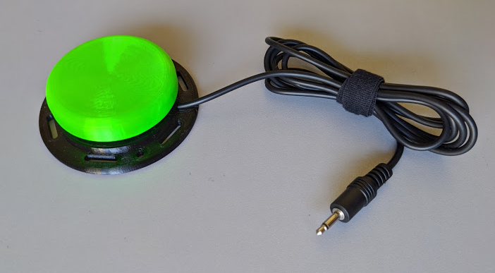
And lastly, we have our new homemade switch. To make it, all you need is a reasonable 3D printer and some very basic soldering skills.
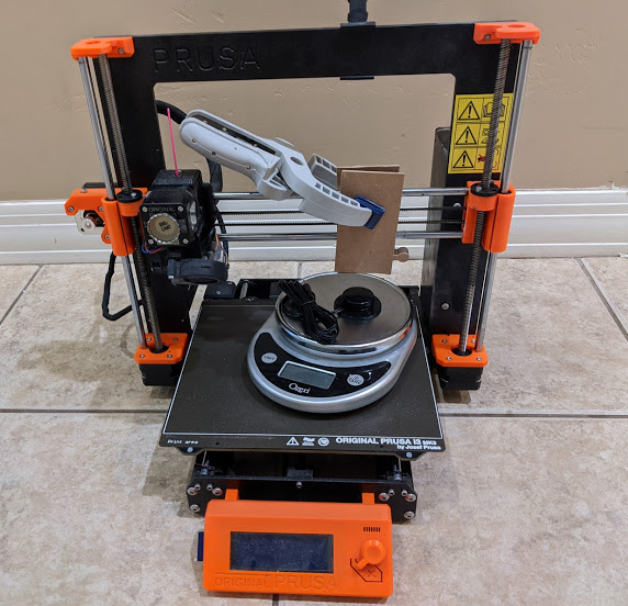
Let's take a look at the test rig. Most of these switches activate over a pretty short throw. In order to get a good idea of what the force vs. displacement graph looks like for each of them, we'll need to measure the force at sub-millimeter increments. Fortunately, 3D printers are great such precise movements.
I attached a short extension below the X axis that would depress the switch as the Z axis is lowered. To avoid slipping, the block of wood that pushes on the switch is directly beneath the lower X axis rod. (My first iteration lacked this piece, and I found that the clamp was not strong enough to keep the two other boards from shifting.) I hooked this rig up to Cura in able to move in increments of 0.1mm.
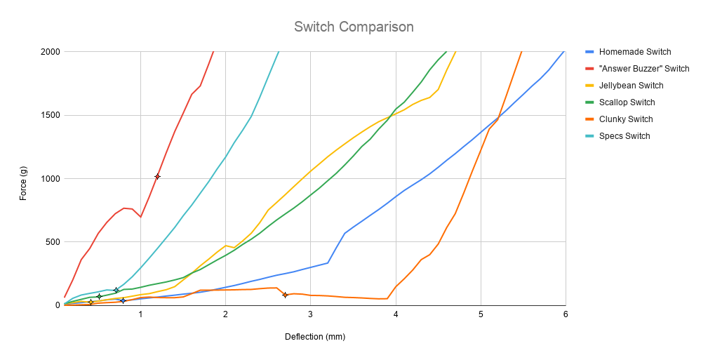
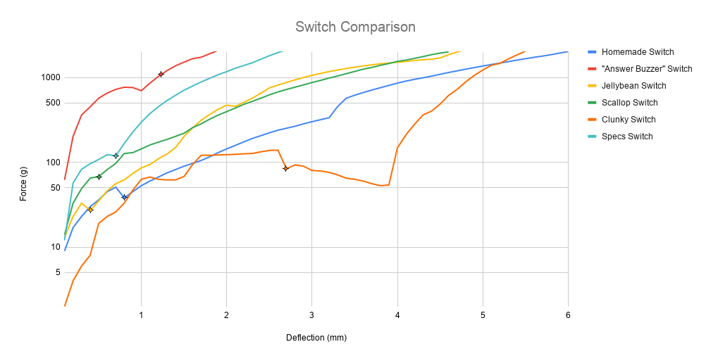
And now the results. I've posted the same graph with both a linear and a log scale-- I think both are
valuable to understand what's going on with these switches. I've also marked each line with a point that indicates when the switch was actually triggered.
Linear:
Logarithmic:
The force required to activate each switch is a hugely important factor in the use of these switches. From this, it's easy to see that the "Answer Buzzer" switch requires significantly more force to activate than any other switch. Keeping in mind that the switch is supposed to make it easier to interact with things, I find that such a large force makes it a pretty poor option for adapting for most users.
My favorite line to see here is for the Clunky Switch. Wow! It's all over the board, and not a smooth curve at all. The negative slope from 2.5mm to 4mm was particularly interesting. Even though the force to activate this switch is much lower, it's really not a good option.
Of the remaining switches, it's worth noting that the force curve is in general very smooth. The shallower the slope, the "softer" and more cushion the switch seems to provide. I think this part of the curve after the switch has activated really plays a large role in the overall feel of the switch. And matching the graph, of these 4 remaining switches, I'd definitely subjectively call the Specs switch the "hardest" and the Homemade switch the "softest."
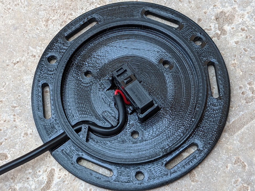
When I started switch adapting toys, I quickly found out that adding a working switch port is only half the battle. It's got to be robust. Siblings will take a switch adapted toy and ruthlessly drag it around by the switch cable. So, I learned the importance of making things strong and "toddler proof."
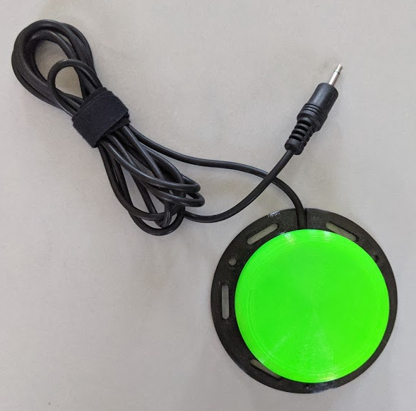
Here, you can see a couple of aspects that protect the switch from being tugged all about. The obvious protection is the curving inside the switch with posts to keep the cable in place. It dissipates even a strong tug on the cable. I'm still a little concerned about the long term protection this will provide with repeated tugging. If that becomes an issue, it may be necessary to place a glob of hot glue around the wire at the base of the switch. So far, I haven't seen any failures here, so we'll see.
The other protection is more subtle. Another failure mode is where the wire goes into the switch. With prolonged use, this point will flex repeatedly and the copper wires can break inside of the sheathing. That's why you see strain reliefs on so many cables-- basically to spread that bend over a larger area. But there's no good way that I'm aware of to add a traditional strain relief here using traditional 3d printing without adding undue complexity. (I'm sure something could be done with TPU, for example, but keeping this easy to manufacture with materials just about anyone would have is a priority of mine). So, instead, I molded a U channel that the wire sits in. This resists the bending, and the resistance increases as the wire gets closer to the entrance hole. The intent is spread the force of a bend over a longer area, as flexing of the wire laterally requires it to be pulled up and out of the U channel. I'm curious to see how this works long term-- crossing my fingers.
Somehow several pictures from my last log entry didn't show up after I posted it. I don't see a way to edit it right now, so I'm posting them here.
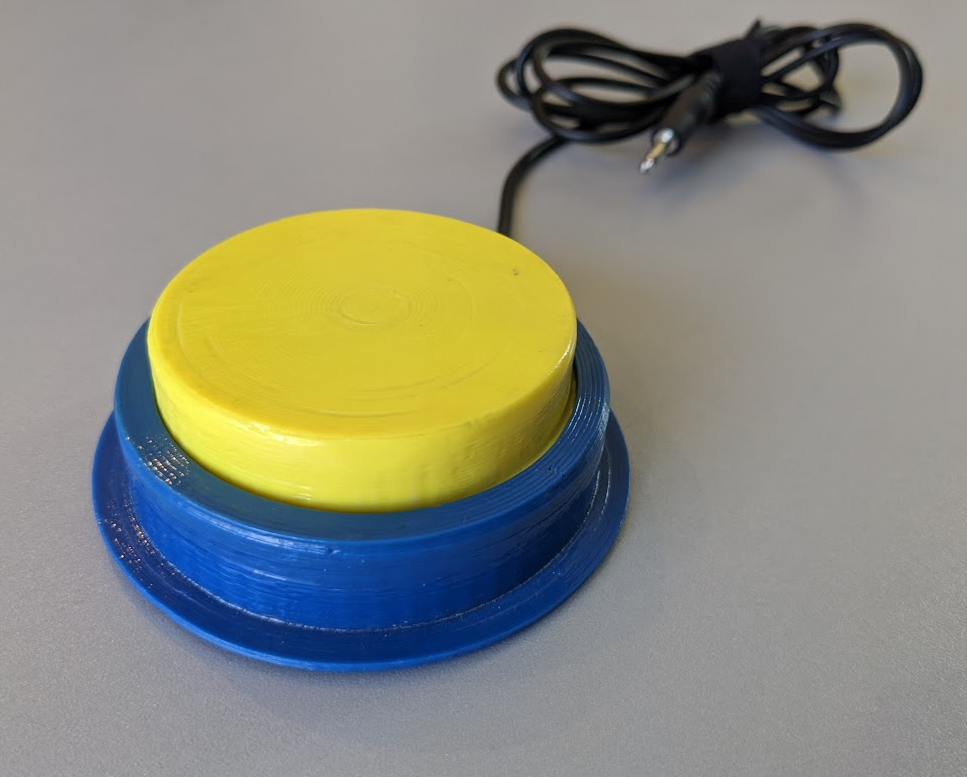
This is the button, once assembled:
For assembling the cap, first the cap insert goes in the cap:
Next, the Cap holder clips in:
The switch is mounted in the base with the wire soldered on, and then the piece above is screwed down (I'll post more pics later of this part of construction-- I don't have any right now). The cap insert is what pushes on the microswitch's button. And the cap holder is the piece that keeps the cap from pulling up/ falling off.
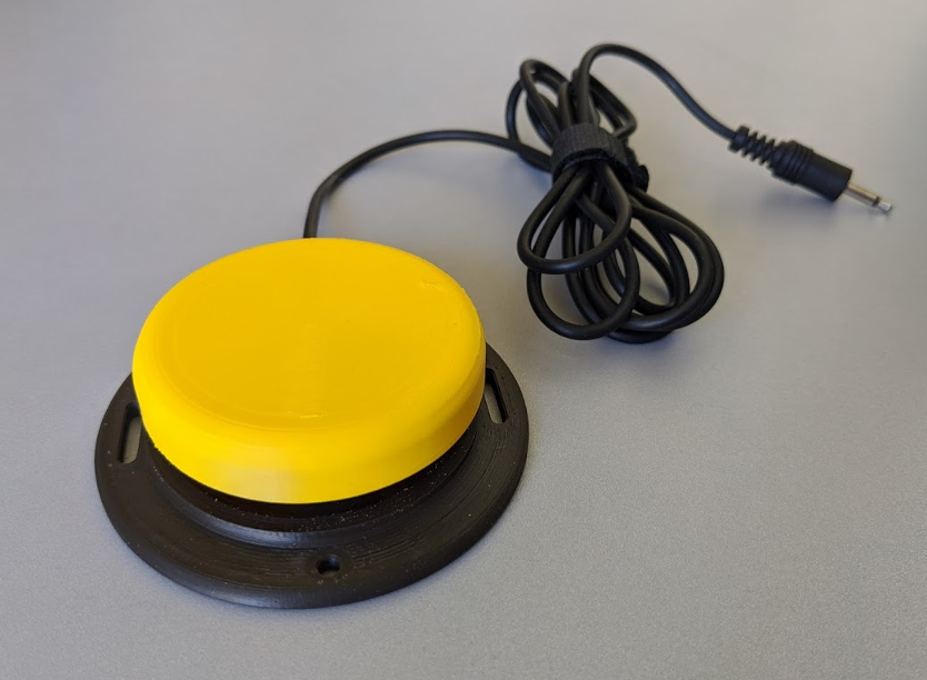
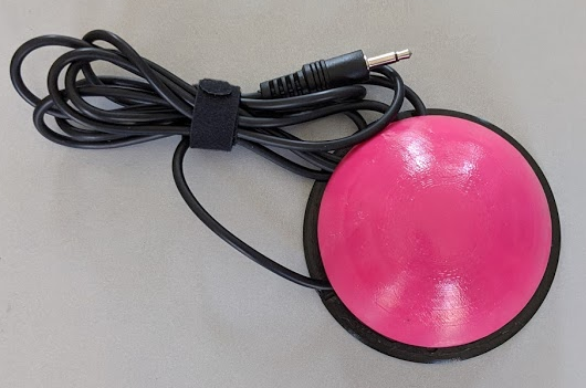
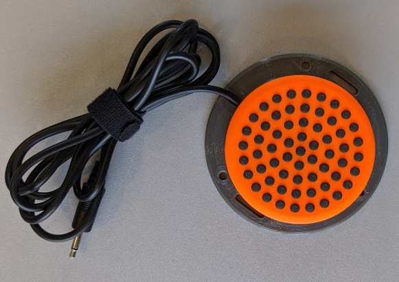
After dozens of revisions, I've got a button that I feel is getting pretty close to meeting all the requirements. Here it is:
It's rather unassuming, but it is a highly reliable switch and takes only ~60g of force, with a uniformity of activation pressure across the top surface. Mechanically, this seems a really good solution.
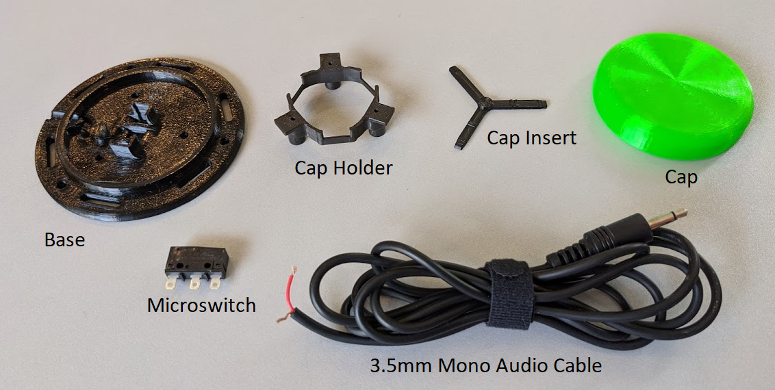
Here is a breakout of the various components:
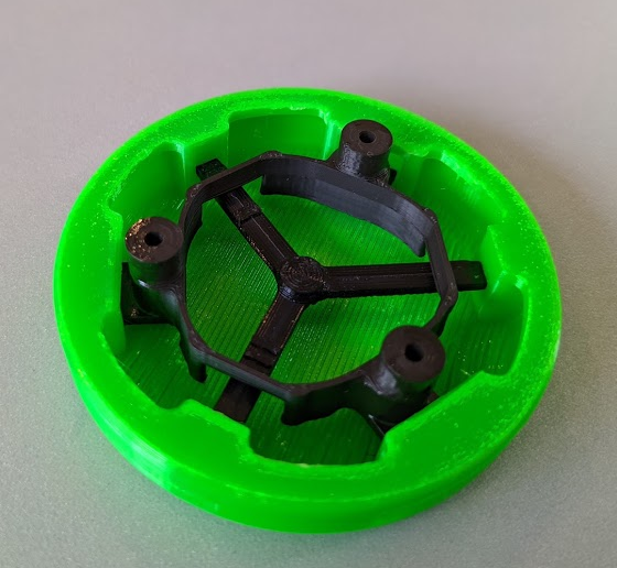
And here's a picture of the cap holder, and cap insert placed in the cap before being screwed down to the base:
And with the cap holder in place:
A key aspect to the "feel" of the switch is that when in its resting (non-pushed) state, the microswitch is already under some pressure, although not activated. If you don't do this, the switch will feel "sloppy" and rattles around. I found this to be tough to achieve consistently and reliably because it requires component precisions that near the layer thickness of the 3d printer (empirically, somewhere in the neighborhood of ~0.1mm).
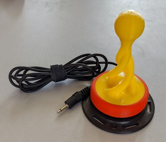
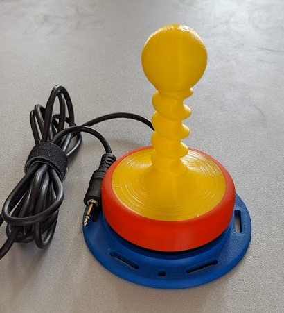
This is one of my early switch designs. I think it's a fairly typical representation of many of the 3d printed adaptive switch designs I've seen. There's a big plunger on top, and it's held captive by a ring around the outside. And that ring is attached to the base somehow (in this case, it's cemented together). Inside, there is a microswitch, with the phono plug attached in a NO (normally open) configuration. It is functional, but it's pretty clunky, requires more force to activate than is desirable (it's ~ 150g ), and really doesn't have a great "feel" to it. At some point, I'd like to graph the force vs deflection. I think this would really help to quantify what I right now see as the "feel" of the switch.
The biggest distinction I've seen between commercial switches and 3d printed homemade ones is how the button is captured. As in the design above, 3d printed switches use a capture mechanism on the outside of the button, like this:
This design generally means that half of the height (or more) is really this ridge that isn't an activation surface. It means that there is a ring around the whole switch that basically "protects" the switch from being activated. When the whole point of these switches is to make it easier for someone to interact with the world, that's a big design flaw.
And that's why most of the commercial switches I've seen move the capture mechanism inside:
 Mike Turvey