-
Hedging Bets - Basic PocketQube Power Supply
02/22/2015 at 16:02 • 0 commentsA couple of project logs ago, I said that I had a couple of options with respect to powering QubeCast Max. One was a power supply connected to the breakout board (ProtoQube), and the other was using an alternative Arduino module.
The previous log showed the alternative Arduino and corresponding adapter that I designed. This might be fine for what I need, but I wanted to explore the other option using my ProtoQube board.
So finally the parts arrived! I've written a blog post about the power supply, but here's the cliffnotes.
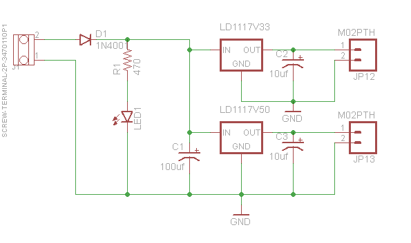
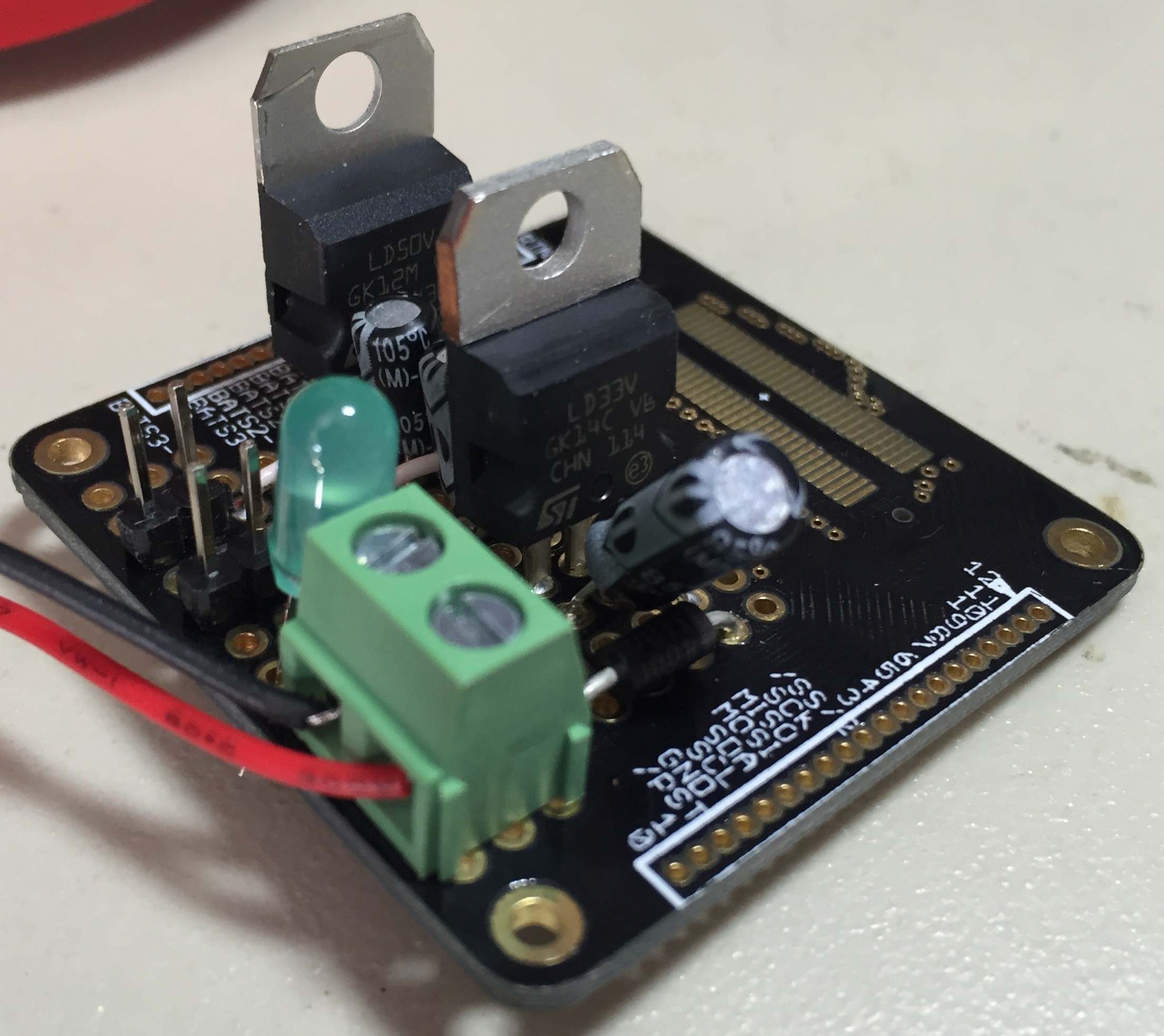
Rather than connect a breadboard power supply to the ProtoQube board, why didn't I just build the power supply on the board! It's a dual output, dual voltage power supply, using only PTH components. 3.3V and 5V output @ 800mA. Here's the schematic:
![]()
Nothing fancy here. The only thing to note is that it needs about 7-12V input to ensure the 5V output isn't too low. Between the voltage drop of the protection diode and the LDO itself, a 6V input ( 4 x AA's) isn't quite high enough.
If anyone's interested, I've put the power supply parts as an option for the ProtoQube board on Tindie
-
PCB's, PCB's, PCB's!
02/16/2015 at 13:24 • 0 commentsHello to all the new followers of the project!
The previous project log I had mentioned a couple of options that would make powering both the Arduino board and the QubeCast Max board alot easier. One option was to make a new arduino adapter based on a version of the Pro Mini that I found on AliExpress - the Beestore Mini.
![]()
You'll notice that the LDO voltage regulator is a bit bigger than usual. That's because instead of the usual 150ma rated SOT23-5 piece, it's a 1A capable AMS1117 LDO. This is plenty to power the arduino itself and the radio module, which, according to the datasheet, draws 540mA @ 5V. I'll be testing at 3.3V, which is the minimum rated voltage, plus the data lines are still 3.3V, even if the modules VCC line is 5V.
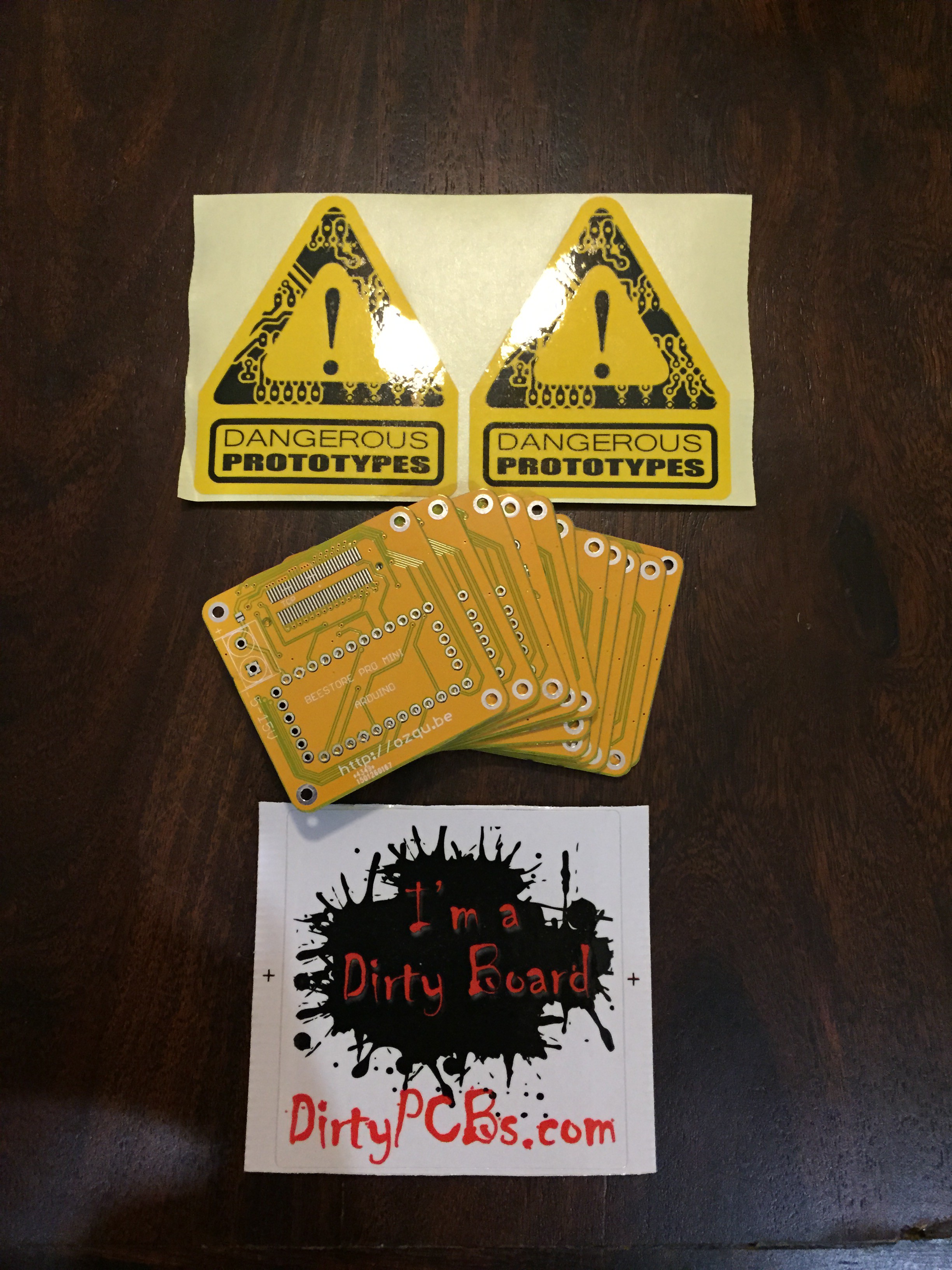
The postman arrived today with the Beestore Mini adapter boards!!!! I used the Dangerous Prototypes DirtyPCB service, in case the stickers weren't clear enough!!!
These adapter boards have the option to solder in a screw terminal for power input, and there's a solder jumper to bridge the power input into the Battery Voltage Bus of the PQ60 backplane if required. The 3.3V rail from the output of the LDO feeds the 3.3V Bus pins of the backplane connector, which is where the radio module will be getting its power from.
Stay tuned for some assembled pictures!
-
Still working on it!
12/26/2014 at 14:23 • 0 commentsI just thought I'd post an update, for all those following the project.
Since creating the first round of PCBs, the PocketQube form factor - PQ60, underwent a few changes. These changes included the PCB size, the hole location and diameters, and the backplane connector pinout.
So rather than push on with the original layout, I decided to update QubeCast Max to match the PQ60 version 1.0 specification, as well as update the Arduino Pro mini adapter board. These are both a work in progress, but it has meant that I've needed to change the SMA connector to a UFL connector, amongst other things.
I also had concerns about powering the board sufficiently. I'm going with 2 approaches for this.
1. Use an additional breakout board connected to the stack to power both the radio and the Arduino
2. I found a version of the Arduino Pro Mini that has an LM1117 LDO with 800mA output
Option 1 is possible because I've created a breakout board, called ProtoQube! I'm even selling it on Tindie. This will let me plug in a breadboard power adapter straight into the power bus of the stack, which will let me run everything.
Option 2 will need a slightly different arduino adapter, because it seems to be different to the regular Pro Mini, plus they haven't arrived from China yet!
I'll post more once I've finalised designs etc
-
Almost there
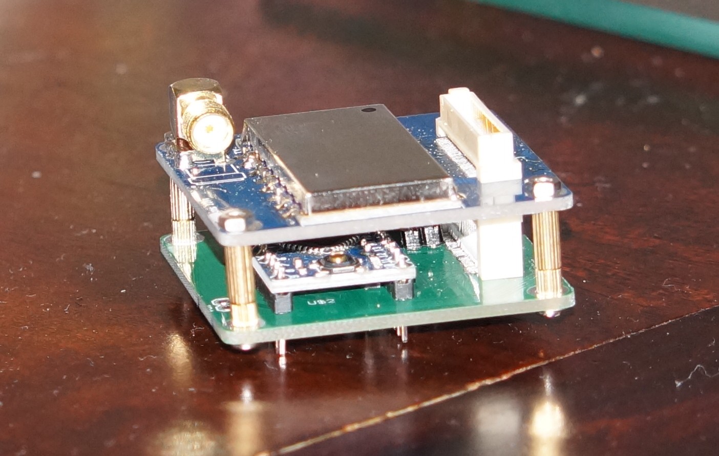
10/09/2014 at 15:21 • 0 commentsSo I bit the bullet and bought a few more of the backplane connectors in various sizes. More importantly, I got the really tall one that will allow the radio board to clear the arduino board! And the result:
![]()
Now if I can only remember exactly how I was going to power the board..... That may be a job for the weekend.
-
PCB #2
08/28/2014 at 14:15 • 0 commentsEven though this project didn't make the top 50, I thought I'd update it as I progress anyway.
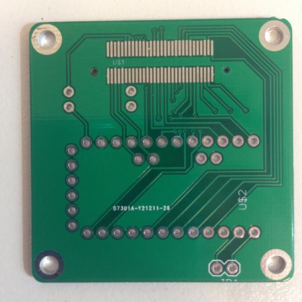
The PCB's for the Arduino adapter board have finally arrived!!
![]()
Seeing as I rushed trying to get them made in time, I didn't do any proper silkscreen or labelling. I had to think about why I'd put the extra pairs of holes!! Pin headers for different power sources is the reason behind them.
And that doesn't help when this board is the base of a stack....So I'll be using right angle headers.
The other issue is that when the Arduino is attached, the height of this board is quite high, so I'll need to source the taller 5mm connector for the backplane. Otherwise QubeCast Max won't be able to attach to it at all!
So now that the boards are here - more parts need to be ordered before I can get it all up and running ( and yes, I could much around with a breadboard and solder wires direct to the radio module, but that would't look nice and neat, would it?)
-
Details, Details....
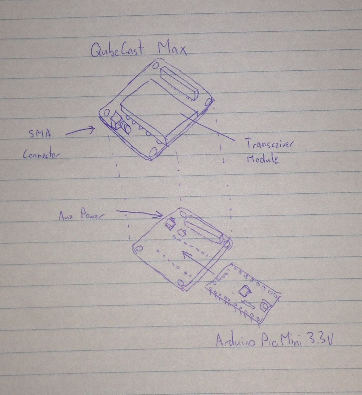
08/20/2014 at 12:23 • 0 commentsSo I need a system design document to meet the entry requirements. In case the design isn't clear from the description, the project logs and the video, here's a basic diagram:
All the software/coding is done on the arduino.
And an actual update - the Arduino Adapter board still hasn't arrived :-(
I've been considering alternatives for powering the test board. The following are some options:
1. A TI TPS63001 Buck/Boost regulator on the Rev2 Arduino Adapter, which will allow the setup to run from a LiPo battery
2. One of the Linear Tech charging IC's that has a built-in regulator....but that may be more expensive. It'll let me run from USB and charge the battery in a single IC though.
3. Find something in the SeeedStudio Open parts library that I just received.
Open to suggestions, so feel free to comment :-)
-
Shipping Notification!!
08/06/2014 at 13:07 • 0 commentsJust received an email with shipping notification for the PQ60 Arduino adapter boards, so it looks like I may be able to have something good to show for the video! Just in time too.
-
Still waiting....
08/03/2014 at 15:59 • 0 commentsThe PCB's from Itead haven't arrived yet, but I thought I'd add a new update.
I tried hand soldering the Hirose FX8C connector to one of the first boards, mainly just to try out the process, rather than to create the working version.
Turns out .6mm pitch is a bit of a challenge, especially when I don't have any really thin solder! It's easier to put a solder blob over the whole lot, then use some solder wick to remove the excess. Probably not the best way, but it seems to work.
The pinout for the PQ60 standard is still in a bit of limbo, as there are some changes being proposed. I may hold off from creating a final version of the radio board until the final pinout is known.
-
More PCB's ordered
07/22/2014 at 15:13 • 0 commentsIn order to actually operate the radio, I need to connect it to an Arduino. I've made an adapter board for a 3.3V Arduino Pro Mini, which connects it to the PQ60 format board. I've added a couple of jumpers to select the power source, as the onboard 3.3V regulator won't power the QubeCast Max!
I'll probably just use a breadboard power supply to feed 3.3V into the Vcc pin or the Arduino, and the 3.3V Bus pins on the PQ60 Connector.
The local new PCB manufacturer isn't accepting orders at the moment :-( so I'm going to try out Itead this time. Just to get the feel of the process :-)
-
Parts have arrived!
07/16/2014 at 15:29 • 0 commentsVersion 0.1 PCB's have arrived from Seeedstudio today, along with the RF modules themselves. There a few more than the five I ordered, so thanks Seeed!
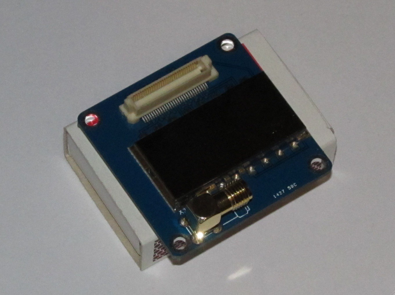
Considering these are the first PCB's I've had manufactured, I didn't expect them to be perfect, from a design perspective. First thing I noticed was that the holes for the locating pins on the 60 pin connector are missing. My footprint in Eagle had the holes in the holes layer. Not sure if it was how I generated the Gerbers, but maybe I should just put them in the drills layer to be safe? If anyone has a better way, please let me know in the comments.
I drilled some slightly oversize holes to allow the connector to sit correctly. A quick dummy assembly followed. To give an indication of size - the board is sitting on a matchbox!
![]()
The silkscreen is missing some of the additional text that I included in the files in the Dropbox, but it also doesn't name the components correctly. Something to fix for the next rev.
Before the boards arrived, I had reviewed the design and found a few issues.
1. I had not followed the correct process for passing through signals from the bottom connector to the top connector.
2. Vcc trace is too narrow for full power
3. Need a capacitor on the Vcc line.
4. Vias for power pins on backplane need to be larger, or more than 1 via for the power bus passthrough pins
Just in time for Rev 0.2, a new local ( in Australia anyway) PCB manufacturing company (Breadboard Killer) has advertised on Twitter a great deal on PCB's - $2.50 per sq inch! So that's 3 of these boards for $7.50!!!
I'd better get moving!
QubeCast Max
QubeCast Max is a high powered radio module for PocketQube Satellites, HAB payloads, or anything that needs a small radio transciever.
 OzQube