Supplyframe DesignLab
-
Mech Update #12
08/28/2020 at 01:53 • 0 commentsNote: The content in this update was from August 18th & August 20th.
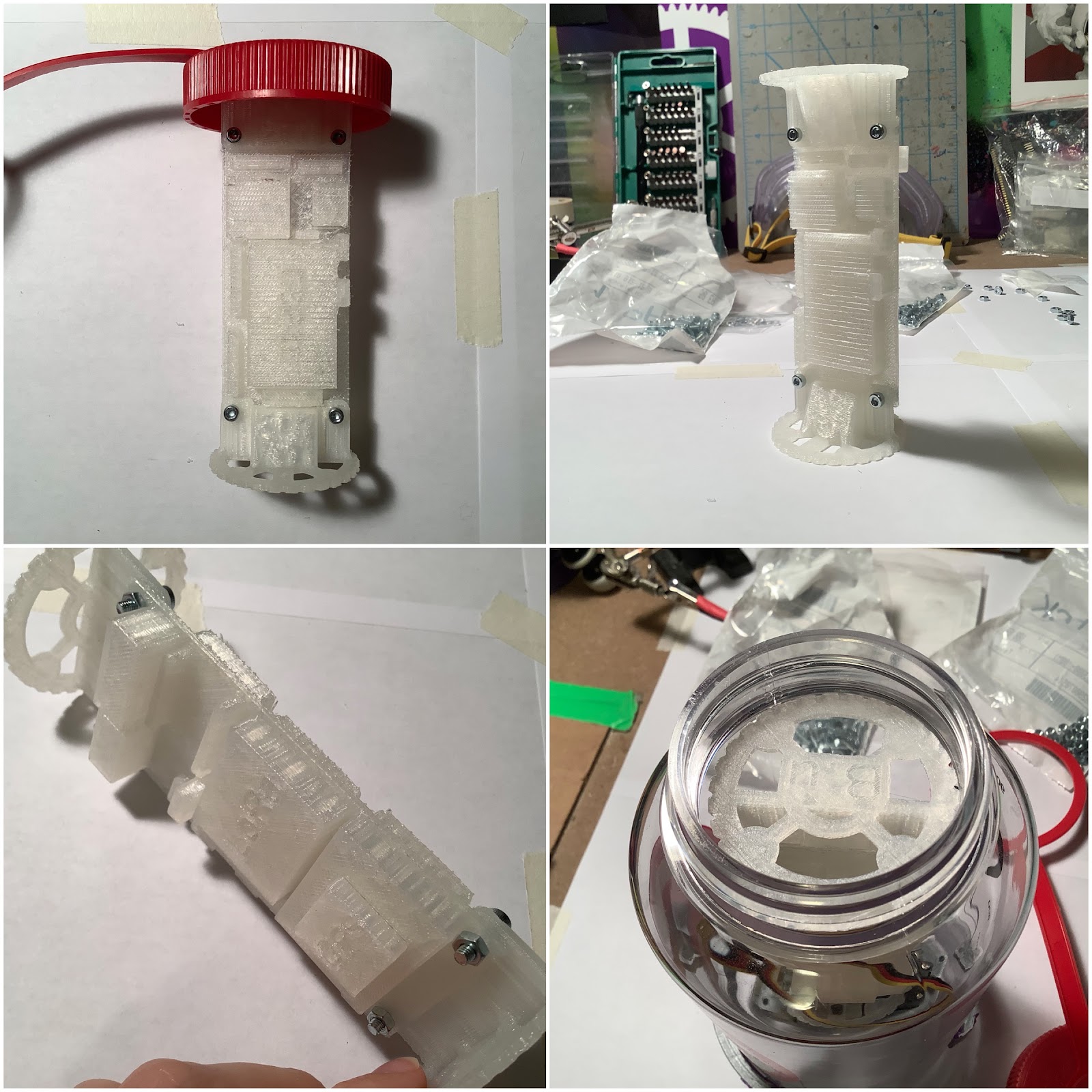
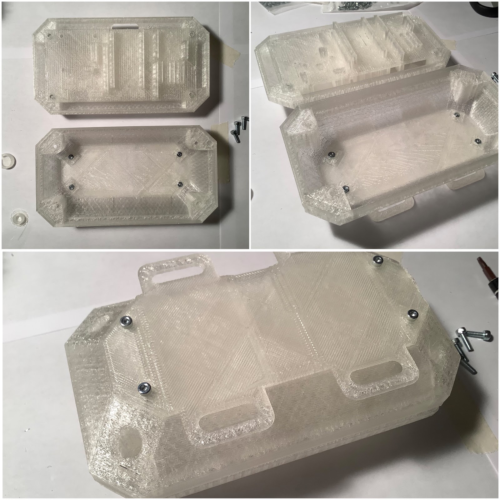
Following on from the Onboard Gateway design in Mech Update #08, an iteration was made, and now it is time to check it with @Leonardo Ward 's circuit board that arrived! Here is what it looks like in the enclosure:
Read on for more tedious details!
---------- more ----------One of the iterations was to extend the outer lip of the upper piece. This would account for any differences in the height. Based on the results of the 3D printed block board, was unsure if this was going to work. Without a board inside, the result looked promising:
What you’re looking at in the above picture is a barely noticeable line where the upper and lower pieces meet. Now, time to add in the board. It still has the same result! Score!
This is where the two pieces meet.
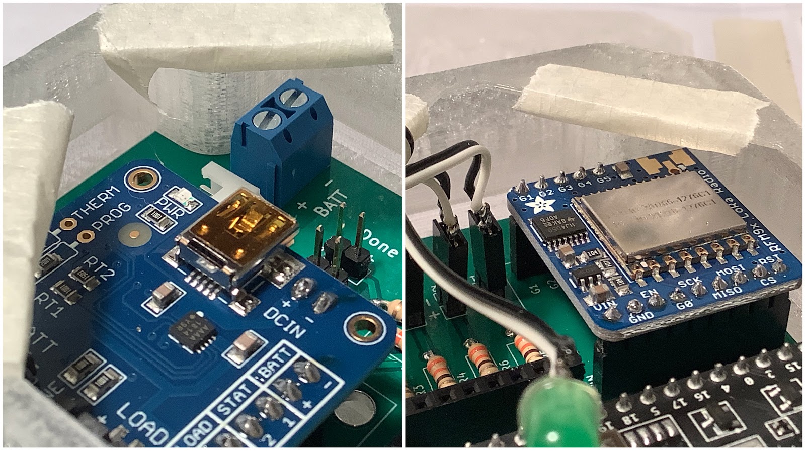
Some of the areas of concern in the enclosure are the battery input port, where there may be limited space to insert a wire on the side closest to the edge. For the LoRa breakout board, it depends on the antenna that will be used. There may not be enough clearance if the antenna is bulky.
Here’s the board now fully assembled, and in the enclosure.
Check out the project log: First Blink! to see the LEDs blink.
-
Mech Update #08
08/28/2020 at 01:39 • 0 commentsNote: The content in this update was on August 13th. Here’s an update that was supposed to follow Mech Update #07, but during the time it was skipped ahead to Mech Update #09. After update #07, it was re-prioritized to work on the Onboard Gateway enclosure rather than the spool box design in order to try to meet shipping deadlines to get the 3D printed pieces to Tobi and Leo.
To get started on the designs rapidly, block prototypes of the circuit boards were printed in order to determine the sizing better. The buoy used the Buoy B board:
The bottom right photo shows that there is some space between the end of the stage piece and the edge of the lip of the enclosure. This will need future modifications with another piece that can attach to the inside of the lid.
The future modification can also be used to move the servo closer to the end of the enclosure:
Read on for more of the design and also the Onboard Gateway design!
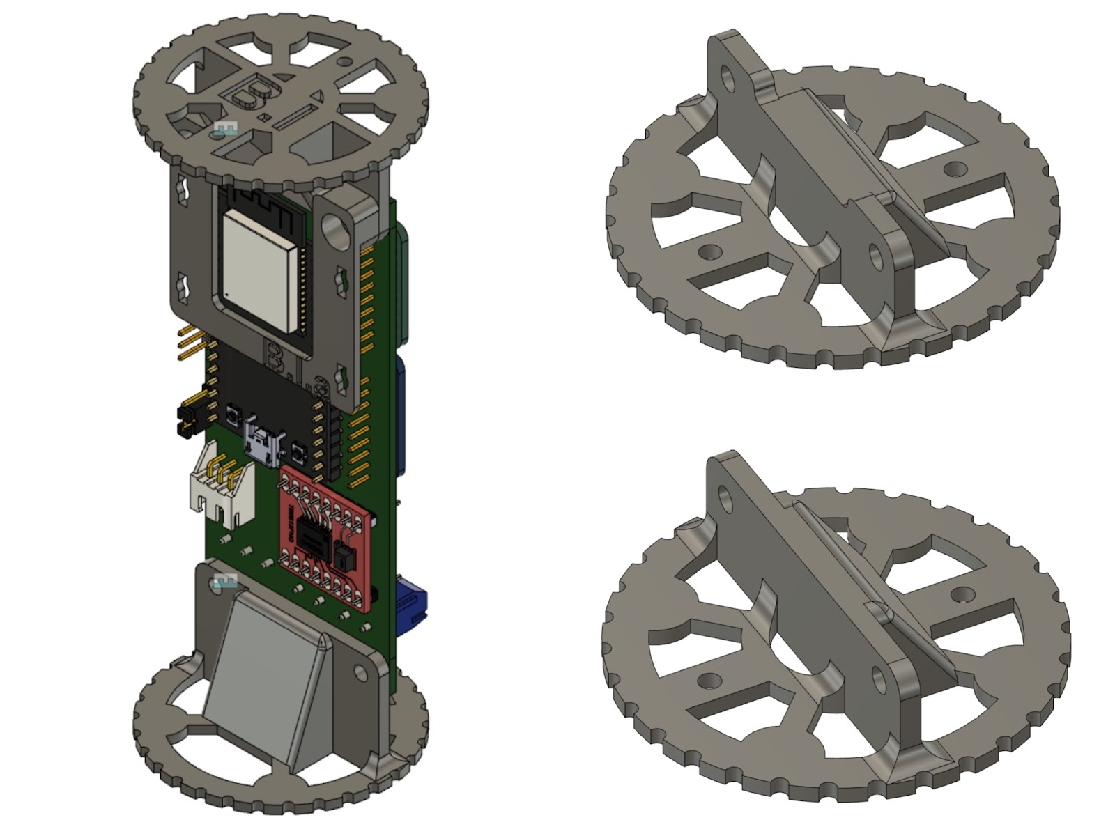
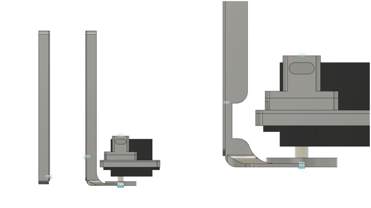
---------- more ----------Here is what the buoy assembly looks like with the board. There could be brackets which also attach to the 3D printed pieces to hold additional sensors or boards, etc.
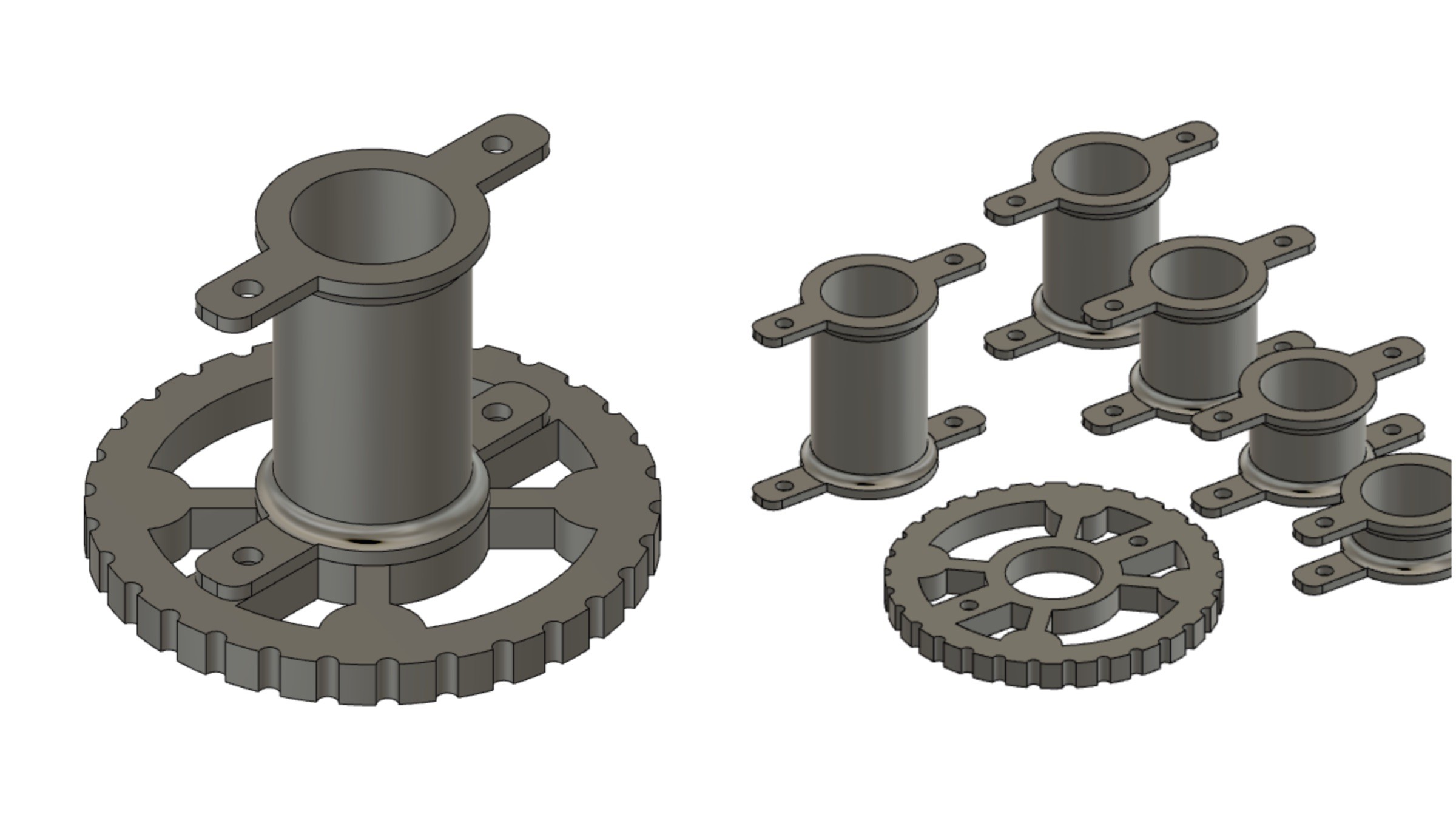
The piece needed to extend the position of the assembly to attach onto the lid consists of a thicker stage to hide the head of the screw in so that it’s flush with the lid, and a variety of spacer sizes for testing:
![]()
The size of the spacer that worked was the longest one.Next up is the design for the Onboard Gateway. Instead of a rectangular box, it has chamfered edges, mimicking a ‘gemstone’ shape. This choice was based purely on aesthetics. To be honest, I’m not sure if that was the right decision during a design sprint when functionality and user feedback matter the most.
A notch in the corner (bottom right) needed to be removed in order to have enough space for the LoRa breakout board. Here’s what the prints looked like:
The block print of the electronics is > 1.6mm, which is the thickness for “usual” circuit boards. This presented some challenges when trying to close it properly.
The bottom of the enclosure features a customizable plate. This one can be used as a wearable, with a band going through the slots. The size of the enclosure seems like it could be placed on a forearm.
After these first few iterations were printed and tested, there were some design fixes for the next iteration. Here are the notes:
This update shows a valiant attempt at trying to do the best effort possible to meet a deadline — by working around the clock with zero sleep that 24 hour period. In the end, this may have led to less than peak performance on my end over the subsequent 2 weeks. That was a learning experience. The prints didn’t meet the deadline, and now we have to re-plan to figure out when to send them.
Stay tuned for future Onboard Gateway enclosure updates (likely in update #12, time traveller!).
-
Buoy B V1.0 - Wiring Diagrams
08/25/2020 at 16:38 • 0 commentsThe following diagrams present the physical connections of the different boards and components of the Buoy B V1.0.
Motors
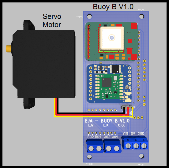
The board was designed to handle 3 different types of motors, those are:
- Servo Motor
![]()
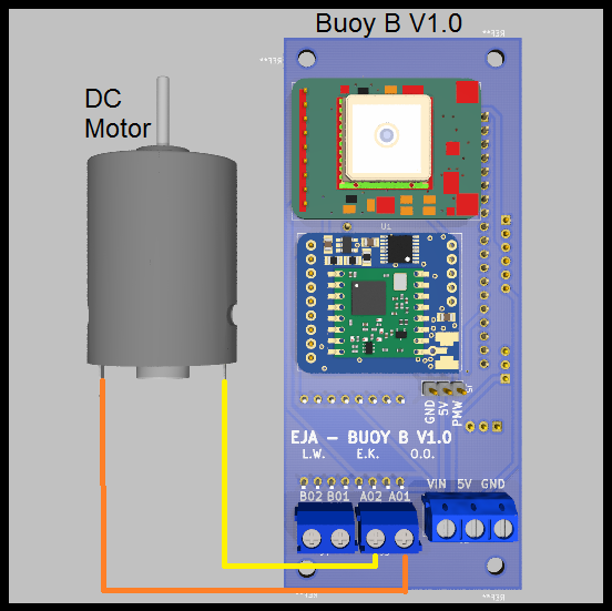
- DC Motor (using the driver TB6612FNG)
![]()
![]()
- Stepper Motor (using the driver TB6612FNG)
![]()
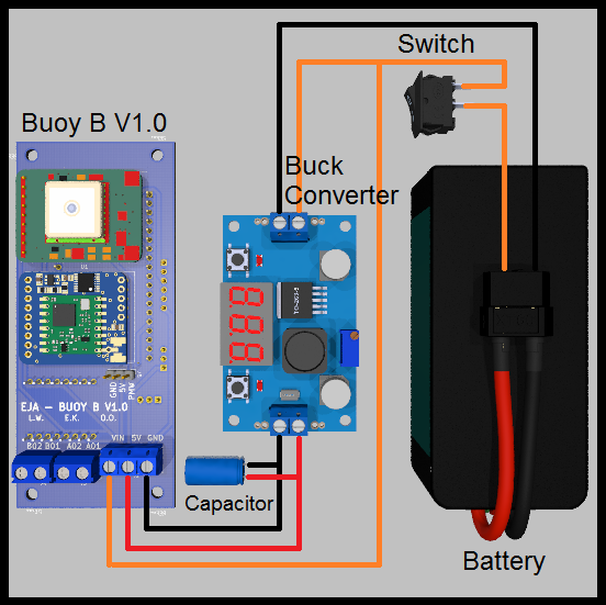
Battery Management
The original design of the board considered the following components:
- Battery (5V < Voltage < 15V)
- PCB Board Buoy B V1.0
- Buck Converter
- Switch
- Extra capacitor
![]()
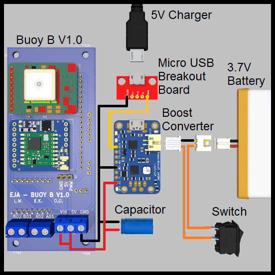
Also, there is an alternative for the battery management, is possible to provide the required voltages with a boost converter and a 3.7V Battery, like the following example:
- 3.7V 1 Cell Battery
- PCB Board Buoy B V1.0
- Boost Converter
- Micro USB Breakout Board
- Switch
- Extra capacitor
- JST-XH 2 Pos female connector and a JST-XH 2 Pos male connector
- 5V Charger (only used to charge the battery)
![]()
This alternative is valid and possible, but is not ideal for longer working time (compared to the first one). It is important to consider the efficiency of the boost converter. The selected boost converter will have a voltage drop at a current higher than 500mA, that should be taken into consideration.
-
Firmware Update #3
08/25/2020 at 12:55 • 0 commentsNow that the two way testing was completed between the Bouy and Onboard gateway,
We now try to test the Wifi logic on the Esp controller, there are some libraries that needed to be added to the onboard gateway in other to achieve it.
// include libraries
#include <WiFi.h>
#include "ESPAsyncWebServer.h"
#include "SPIFFS.h"
And then the initial include functions SPI.h and LoRa.h
Going forward, network credentials will need to be set based on the user ssid and Password!. The device will connect to Wifi and confirm the ssid and password and print out the assigned IP address
// Connect to Wi-Fi
  WiFi.begin(ssid, password);
  while (WiFi.status() != WL_CONNECTED) {
    delay(1000);
    Serial.println("Connecting to WiFi..");
  }

  // Print ESP32 Local IP Address
  Serial.println(WiFi.localIP());
Currently we have not designed the complete web server to be so fancy, we only want to set the GPIO high or Low and send the information to Bouy and if the message was sent, it prints it on serial.
// Route to set GPIO to HIGH
  server.on("/on", HTTP_GET, [](AsyncWebServerRequest *request){
    String message = "ON_REQUEST";
    // send a message to LoRa Node
    LoRa_sendMessagetoNode(message);
    Serial.println("Send Message to Node!");// Route to set GPIO to LOW
  server.on("/off", HTTP_GET, [](AsyncWebServerRequest *request){
    String message = "OFF_REQUEST";
    // send a message to LoRa Node
    LoRa_sendMessagetoNode(message);
    Serial.println("Send Message to Node!");
-
Firmware Update #2
08/25/2020 at 12:35 • 0 commentsA quick test to see if the connections on the gateway are accurate so, we try to blink all the LED just to see it blink and be sure they are all working
Here is the code.
#define LED1 22
#define LED2 5
#define LED3 16
#define LED4 17

void setup() {
  // Set pin mode
  pinMode(LED1,OUTPUT);
  pinMode(LED2,OUTPUT);
  pinMode(LED3,OUTPUT);
  pinMode(LED4,OUTPUT);
}

void loop() {
  delay(500);
  digitalWrite(LED1,HIGH);
  delay(500);
  digitalWrite(LED1,LOW);
  delay(500);
  digitalWrite(LED2,HIGH);
  delay(500);
  digitalWrite(LED2,LOW);
  delay(500);
  digitalWrite(LED3,HIGH);
  delay(500);
  digitalWrite(LED3,LOW);
  delay(500);
  digitalWrite(LED4,HIGH);
  delay(500);
  digitalWrite(LED4,LOW);
}
And blink result for the above code was tested by Erin, she also share the picture of the test here
-
Firmware Update #1
08/25/2020 at 12:25 • 0 commentsThe first firmware testing invoves setting up the LoRa environment by testing the communication between the two devices "Bouy and Onboard gateway", part of the programming parameters was to include SPI.h, and LoRa.h we shall use the includes details for the communciation and connection interface to the LoRa for both the onboard gateway and Bouy.
We also selected the frequency for the contry of deployment, for the testing we select 915Mhz during the testing purpose, but is eazyly adjustable from the code, or check out your country LoRaWAN frequency
For Bouy, it will print the details below if the connection was successful or failed.
// wait up to successfully LoRa initialization
  if (!LoRa.begin(frequency))
  {
    Serial.println("LoRa init failed. Check your connections.");
    // if failed, do nothing
    while (true);
  }

  Serial.println("LoRa init succeeded.");
  Serial.println();
  Serial.println("LoRa Simple Node");
  Serial.println("Only receive messages from Gateways");
  Serial.println("Tx: invertIQ disable");
  Serial.println("Rx: invertIQ enable");
  Serial.println();
For Onboard Gateway, which is also similar with Bouy
  // wait up to successfully LoRa initialization
  if (!LoRa.begin(frequency))
  {
    Serial.println("LoRa init failed. Check your connections.");
    // if failed, do nothing
    while (true);
  }

  Serial.println("LoRa init succeeded.");
  Serial.println();
  Serial.println("LoRa Simple Gateway");
  Serial.println("Only receive messages from Nodes");
  Serial.println("Tx: invertIQ enable");
  Serial.println("Rx: invertIQ disable");
  Serial.println();
And they both loop back a message that says "node is working" and "gateway is working" respectively
-
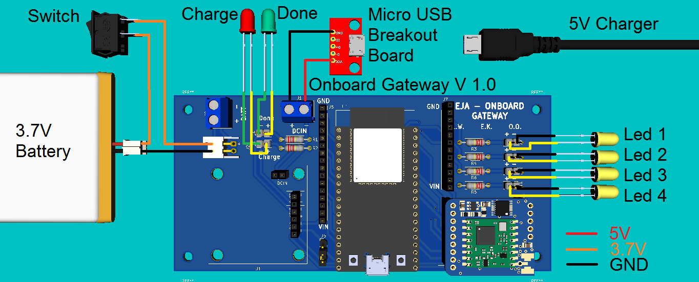
Onboard Gateway V1.0 - Wiring Diagram
08/23/2020 at 03:05 • 0 commentsThe following diagram presents the physical connections of the different boards and components of the Onboard Gateway, that includes:
- 3.7V 1 Cell Battery
- Leds (Charge, Done and 4 Miscellaneous)
- PCB Board for the Onboard Gateway V1.0
- 5V Charger (only used to charge the battery)
- Micro USB Breakout Board
- Switch
![]()
-
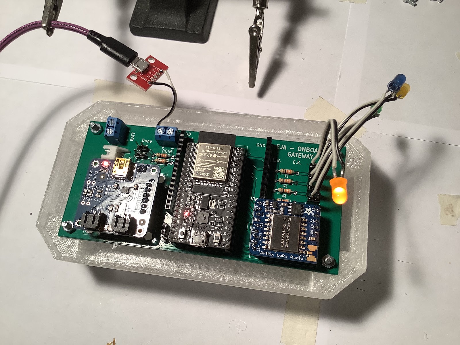
First Blink! Onboard Gateway
08/21/2020 at 04:22 • 0 commentsWe have achieved first blink for the Onboard Gateway!
![]()
Here’s what the Onboard Gateway board looks like, all assembled:
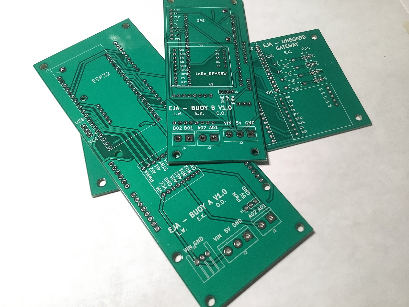
The circuit boards arrived in Canada earlier this week:
This is a 3 continent effort: circuit boards designed in Venezuela by @Leonardo Ward, code developed in Nigeria by @Oluwatobi Oyinlola, and assembled into the 3D pieces made in Canada by @Erin RobotGrrl.
Tobi is going to get circuit boards made locally as well, and he will send a few to us — that’s going to be really cool. The circuit boards also arrived in Pasadena, CA late last week, and these will be shipped from DesignLab to Venezuela and Nigeria - thanks @Giovanni ! Next steps is more testing, and Buoy A and Buoy B boards have to be assembled.
-
Mech Update #11
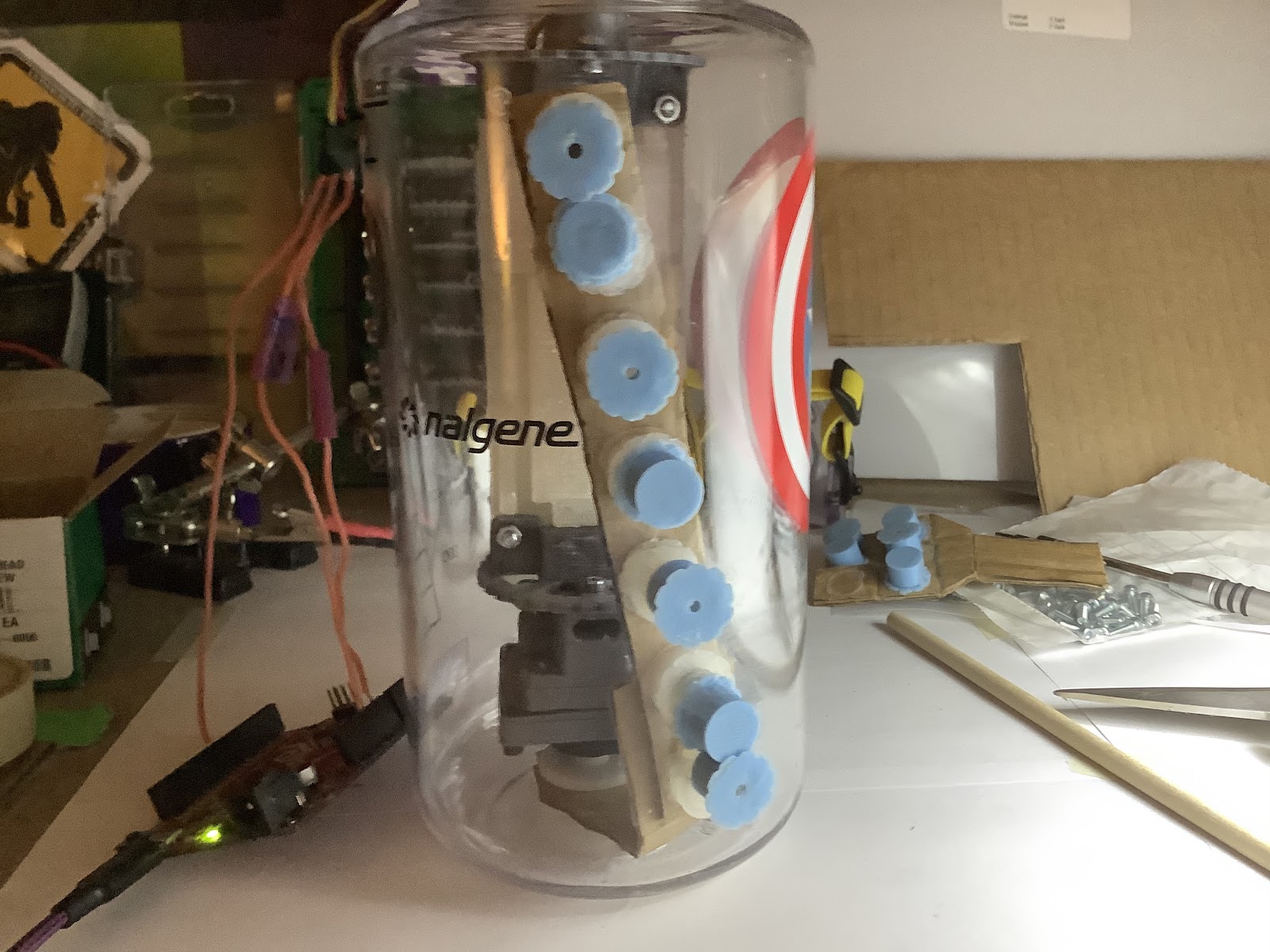
08/20/2020 at 05:11 • 0 commentsThe previous experiment left off with the assumption that a bearing of some sort would be needed on the upper end of the interior wiper. Looking back at it, it is possible that the angle formed when the interior servo arm was moving could have been caused by the cardboard. Before diving into (another) lengthy design process, verifying this happens in rigid material was needed.
The hypothesis for this experiment was that the rigid exterior magnet wiper would follow the rigid interior wiper, and the lagging angle would be minimal compared to the cardboard experiment.
At last, the result validated this hypothesis! And provides us with a usable solution to build on for the next step in the buoy release mechanism design.
![]()
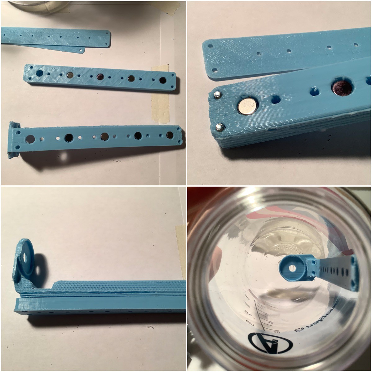
Here is the experiment setup:![]()
The magnets were embedded into the wiper. 4 were used for the internal, and 5 were used for external. Of interest is the bottom right image, it seems there is an offset of the servo horn. Extending this by 7mm may help reduce some of the twisting movement.The reason why the number of magnets for the internal wiper needed to decrease (on this iteration) was because a notch for the servo bracket to pass by when the internal wiper is rotating.
![]()
With this result, now we can iterate to build the swivelling retainer that would be situated on the top plate of the spool box where this buoy would be placed for the descent, then after some time actuate the magnetic wiper assembly to be released. -
Mech Update #10
08/18/2020 at 08:08 • 0 commentsThere is new progress following yesterday’s experimentation. It looks like a possible solution will be a magnetic wiper extending across the length of the enclosure. This can be coupled to an exterior wiper. The exterior wiper would pivot a bracket that would be holding the buoy to the spool box. Once it rotates to a specific angle, the buoyancy of the buoy will release it from the hold to its destination of the surface of the water. Here’s a look at the experiment result that output that idea:
![]()
To reach this idea, there were iterations that built on each subsequent experiment. Let’s take a look at them.Read on for all the info
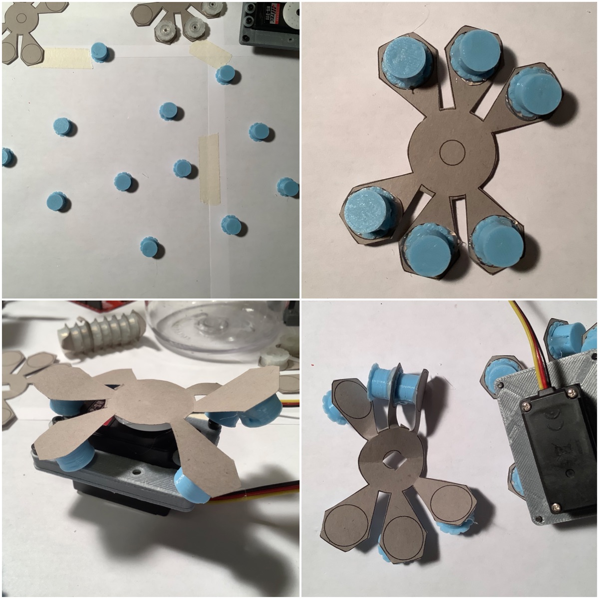
---------- more ----------Following on from yesterday, time to test with the stronger (taller) magnets. These were enclosed into a 3D printed shell so they could be glued to a variety of surfaces for quick testing. The petal piece was attached to the servo horn. The bottom right shows a problem that was starting - the magnets were attaching to each other and making it difficult to be spread apart.
It fit into the enclosure, however with some unsuccessful fidgeting to unstick the magnets from each other, it became clear this wasn’t going to work. The number of petals were reduced to 4. This worked for one side (bottom left), however for the other side, the magnets were attracted to the screws more than the external petals (bottom right).
This idea was clearly not working. Onto the next, which was using the outer wall as the surface, instead of the bottom. To prototype this, made some servo horns out of cardboard and attached the magnets to it. The first try worked, then improved it by adding bends.
![]()
![]()
Here’s what happens when one of the magnets on the interior disconnects:![]()
Next up was to try making this stronger. This was done by adding an array of magnets.Here’s what the result looked like:
![]()
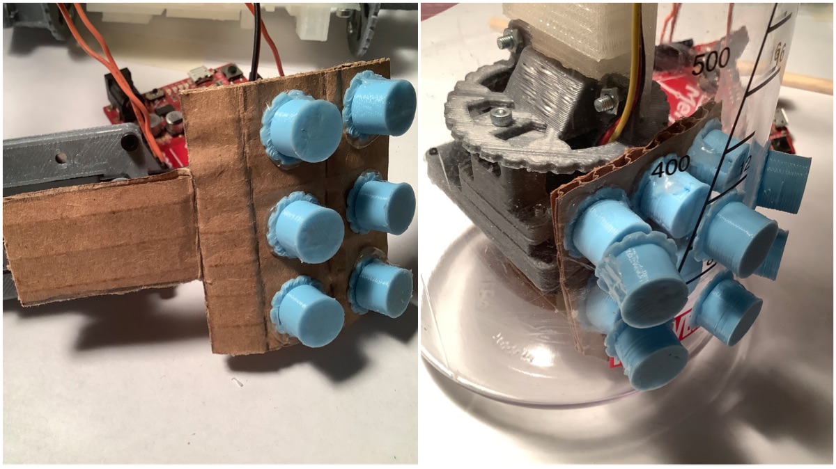
To modify this even more, the polarity of the magnets was swapped for every 2nd magnet. This meant that the adjacent magnets were not repelling each other anymore, but instead attracting.Here’s what the result looked like installed:
Here is the video of that in action:
![]()
The moment when realizing this idea was heading in the right direction is seeing two magnets that disconnect, and there is enough force that they are able to reconnect.![]()
There was a shortcoming to this idea, which is that it’s going to be difficult for it to be an entire “seatbelt” for the buoy against the buoyancy force unless it is covering the entire length of the enclosure. This observation is where the wiper idea originates from. A long strip of magnets, alternating their polarity, which attaches to a similar long strip externally.Here it is in action:
![]()
My hypothesis was that the upper portion of the wiper would lag behind the lower (where it is closer to the servo horn being driven). This was proven true. One way that this effect could be mitigated is to have a perpendicular piece from the wiper extend to one of the stages in the buoy’s construction. This piece could rest in a groove that would support it as it moves along. Additionally, this would be made from rigid PLA, not bendable cardboard. There’s not very many spare millimeters for the buoy stages, so some tinkering and 3D print iteration will be needed to find where it can fit…!It’s a relief to have a new idea to try after this promising experiment! As you can see, the key to reaching this idea was building on the iterations previous, and this was a relatively fast process compared to CAD modelling -> 3D printing -> assembly.
The next steps will be to try the perpendicular piece sliding on one of the stages idea; in order to validate that it would reduce the lagging at the upper portion. As well as making some of the other pieces in rigid plastic, to remove those as variables in this issue.
Other updates: the 2nd iteration of the onboard gateway enclosure is complete. PCBs are here, and additional electronics are here too. The next steps there are to solder the onboard gateway, and verify the dimensions fit for the enclosure. Then, 3D printing of that can commence in order to send to Leo and Tobi. Electronics pcbs next steps …….. sanitizing the box, opening the package, and sanitizing the boards. Then photos will be shared!
2021 HDP Dream Team: EJA
Learn more about Team EJA's intelligent buoy, and how their solution will help the global fight against ghost gear.