 Andrew Mitz
-
11Glue charger board into place
Top half of case. Fit the charger board into its position. It should fit with the connectors facing the inside of the case and circuit board pushed partially into a slot inside the case. The silver micro USB connector should be accessible from the outside of the case.
Tape down the wires, if necessary, to keep the board in position. Epoxy the charger board into place using the two rear plastic posts and the flat tab behind the charger. The flat tab is there to tolerate the force of the repeated plugging of the charger cable. Epoxy between the flat tab and the circuit board (which can include the top of the circuit board) will provide good stability.
![]()
-
12Glue the PowerBoost circuit board into place
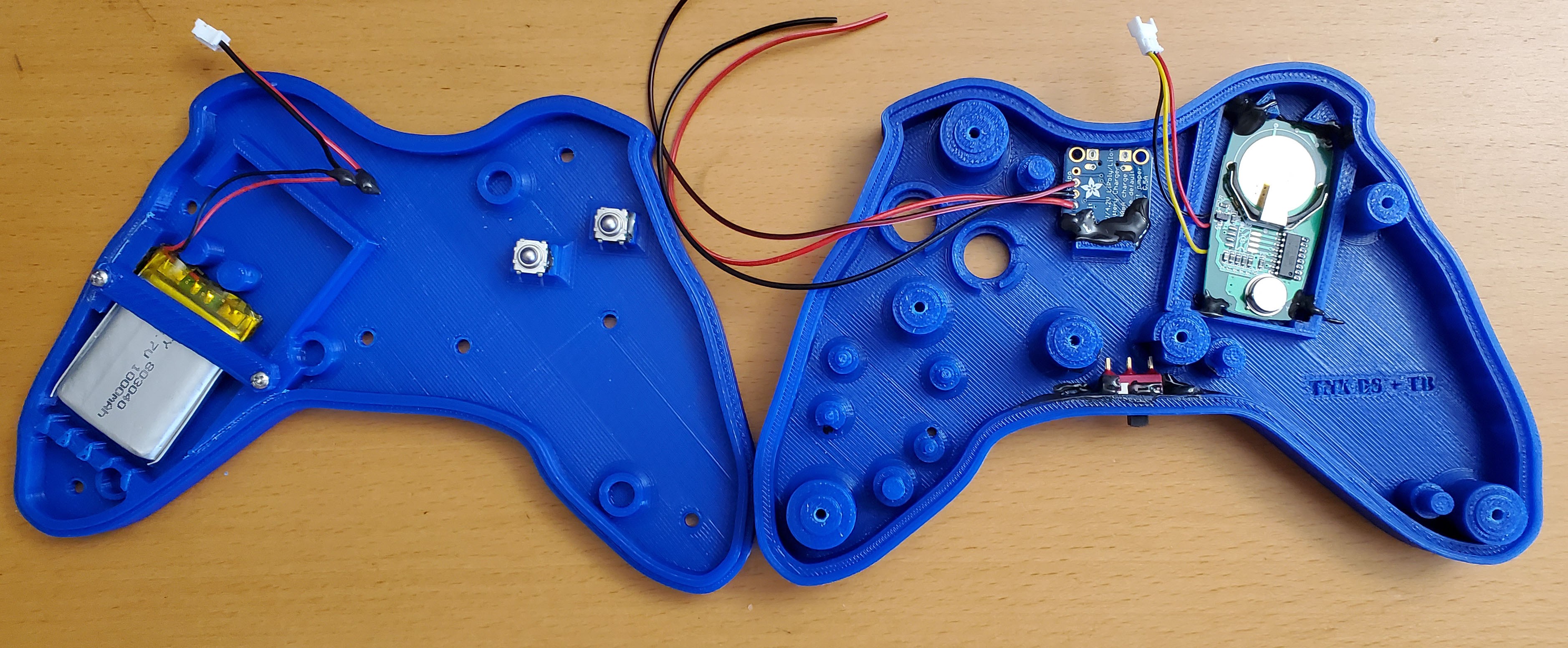
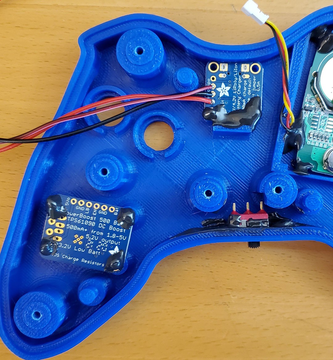
Top half of case. If the PowerBoost comes packaged with a USB connector, throw away that connector. It will not be used. Place the PowerBoost circuit board upside down (components facing the inside of the case) on its 4 plastic mounts. Note its orientation carefully. The straight row of contacts (labeled 5v, GND, LB, EN, etc) should be facing toward the top of the controller (the direction of the two large pushbutton holes).
Glue the 4 corners. Two of the corners have indicator LEDs on the component side of the circuit board. Try not to block the light getting from these LEDs through the case of the controller with any drip from the epoxy.
Use excess glue around the side of the circuit board onto the posts at each top post to create a stronger connection to the post. This picture does not have that extra glue. The extra glue helps make the controller more tolerant to being dropped on the floor. It is fine to cover the electrical contact for the USB connector (which is not used), but try not to cover the straight row of electrical contacts. Extra glue around the bottom posts is possible, but look carefully at the LED indicator holes and avoid blocking the light path for the LEDs.
![]()
-
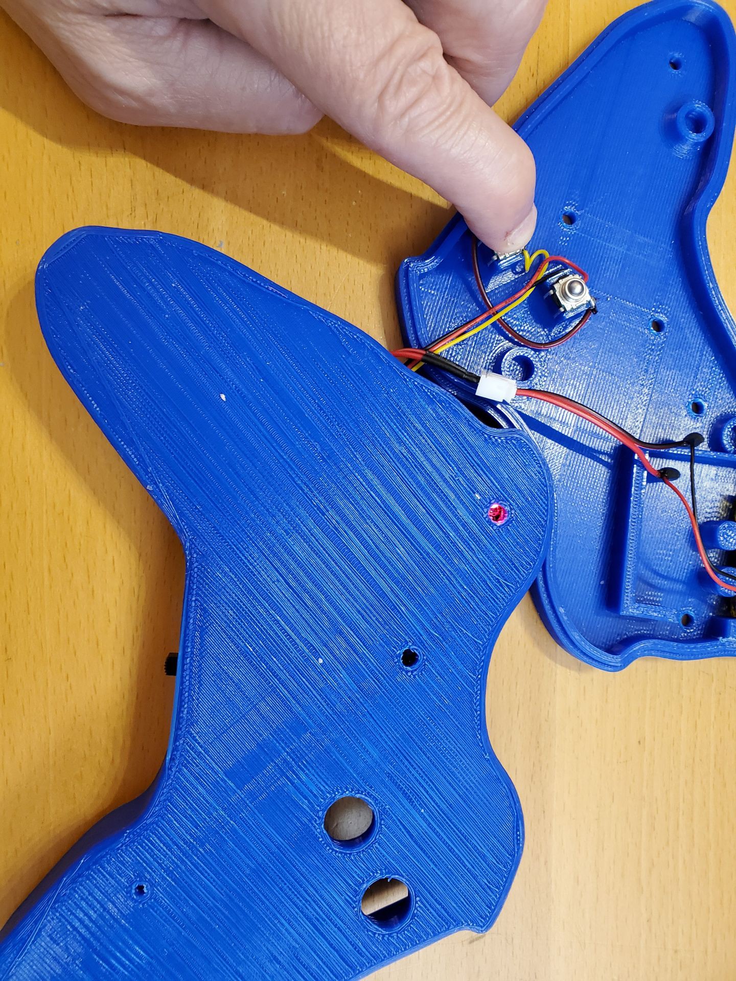
13Solder wires to the tactile switches
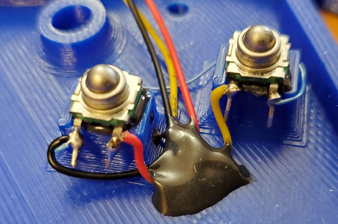
Bottom half of case. Find a Micro JST 1.25 mm 3-pin connectors that is the mate to the connector used in step 6. Be sure to use the mating end, not the same gender used for the keyfob. Wire the tactile switches to the connector wires. Note the thin blue jumper wire that connects the two switches together in the closeup picture. Install a jumper wire first. The black wire of the connector goes to the jumper wire. The red wire goes to the switch on the left and the yellow wire goes to the switch on the right. Use epoxy to tack down the cable wires as shown in the closeup.
![]()
-
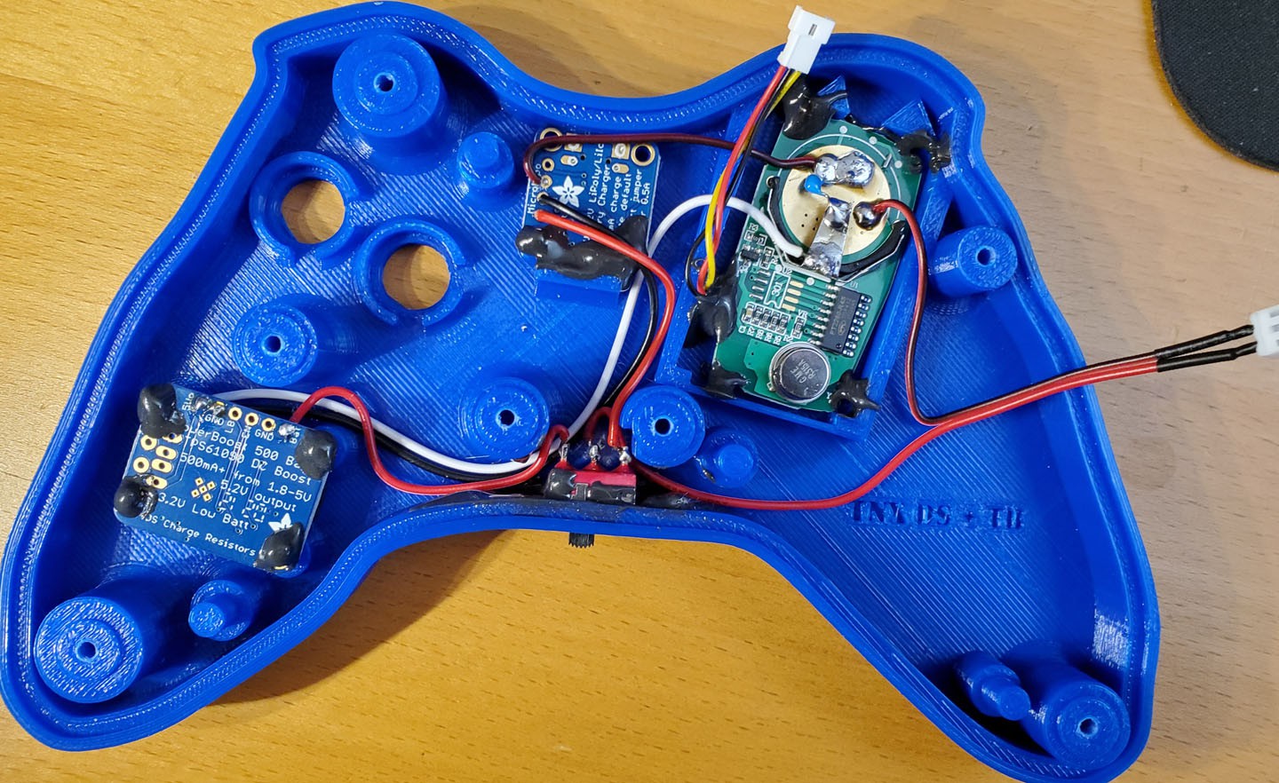
14Top wiring 1: Charger board to slide switch
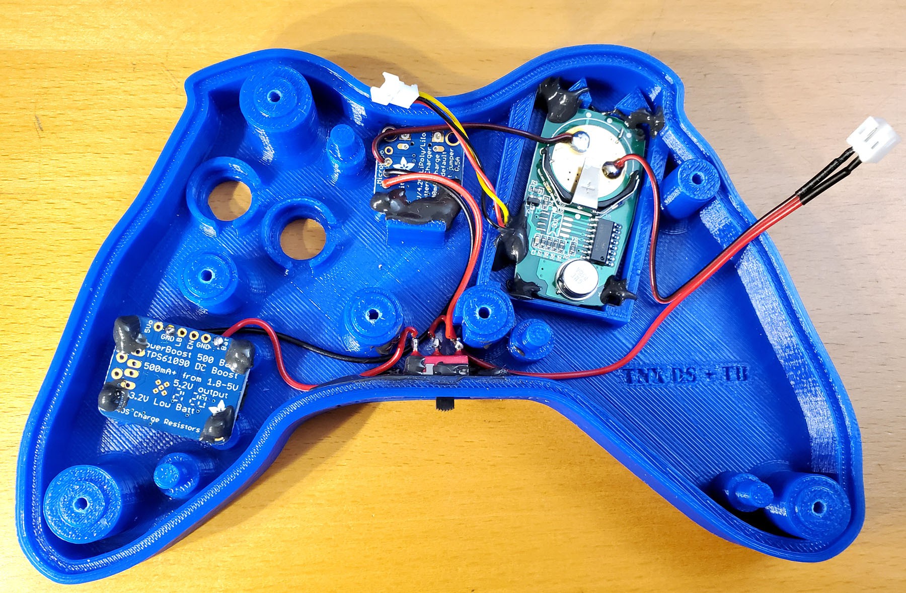
Top half of case. When wiring up the slide switch, note the labels on the case: chrg and ON. In the ON position, the switch connects the battery to the PowerBoost board. In the chrg position the switch connects the battery to the LiPo Charger board.
Start with the LiPo charger board. It has a wire to the BAT pin on it already. Use this wire. Measure the distance to the switch on the chrg side. There is a notch cut into a post to make room for the solder connection. Strip and solder this connection. Try not to melt any surrounding plastic.
Use this photo for the slide switch wiring.
![]()
-
15Top wiring 2: Battery connector to slide switch
Top half of case. Solder the power connections for the battery (the unused side of the JST-PH Battery extension cable). The red wire goes to the center of the slide switch. The black wire goes to the large circular area of the keyfob. Check the photograph in the previous step (Step 14) for how much wire to use. Note the red wire will be cut longer than the black wire.
-
16Top wiring 3: Ground connections
Top half of case. There are two ground wires on the LiPo charger. Stretch one over to the large circular area of the keyfob. (See photograph in Step 14.) Cut to length, strip it and solder it to the circular area (in common with the black wire of the battery connector).
Route the other ground wire of the LiPo charger past the slide switch and over to the PowerBoost circuit board. Cut the wire to length, strip it and solder it to one of the two solder pads marked GND. Now all the grounds are connected.
-
17Top wiring 4: PowerBoost board to slide switch
A new wire will be needed from the switch ON position to the BAT pin on the PowerBoost board. Measure the wire, cut and strip both ends. Solder the wire in place.
-
18Top wiring 5: Power to keyfob
Top half of case. The arm of the battery holder is used as the positive connection to the keyfob. It connects to the +5v connection of the PowerBoost board. Measure a wire, route it past the switch and cut the wire to length. Strip both ends. Solder one to the +5v connection and the other to the arm of the battery holder on the keyfob board.
-
19Top wiring 6: Ceramic capacitor
Top half of case. This was a change made later. To assure proper keyfob transmission, solder a ceramic capacitor (0.33 to 1.0 uF) between the arm of the battery holder and the large circular area of the keyfob. The easiest way is to trim the capacitor leads to under 1/4" each. Bend one lead so it is flat on the circular area. Solder it in onto the circular are. Bend the other lead to reach the arm of the battery holder. Trim off excess wire. Solder that lead in place. The wire that was on the arm may come unsoldered, so hold it in place and resolder it. Step 7 has a nice close-up of the capacitor.
![]()
-
20Test 1
Double check all the connections. Now check again.
Turn the slide switch to chrg. Join the two circuits by connecting the battery and switch connectors. Turn the slide switch to ON. Watch the top of the controller while pressing one of the tactile switches. The red LED on the keyfob should light up. Test the other switch.
![]()
Adaptive wireless switch
Adaptive switches are often used by people with limited hand function. This switch looks like a game controller and uses a low cost keyfob.
Discussions
Become a Hackaday.io Member
Create an account to leave a comment. Already have an account? Log In.