 Andrew Mitz
-
1Drill and tap battery hold-down
Bottom half of case. Clear out battery hold-down holes with a #50 drill bit and pin vise. Carefully tap the hole with 2-56 tap.
-
2Drill and tap mounting posts
Top half of case. Very carefully drill the 7 thick round mounting posts using a #42 drill bit and pin vise. Go slowly and clear out waste a couple of times while drilling holes.
Stop here. See Log file: "Using heat-set threads for mounting posts". The heat-set threads work much better than tapping the plastic directly. Optionally, you can continue with this step and tap the plastic directly. Step 7, below, shows heat-set inserts in three of the mounting posts.
Tap these holes with a 4-40 tap. Tap the holes even more carefully than drilling. Keep the tap clean. Do not drive the tap too deep. The posts can snap off.
-
3Cut off battery connector. Wire on new connector.
[Warning: This step has risks. The battery is very powerful. Do not let the two battery leads touch each other.] See Step 11 for a picture. Cut the connector off the battery keeping 2 to 2.5 inches attached to the battery. Do not cut the two wires at the same time with a metal tool. Cut each lead separately to avoid shorting them. Cut the JST-PH battery extension cable so that the female connector (the connector that has no exposed metal) has about 2 inches of wire on it. Save the other end of the extension cable, you will need it. Strip (that is, remove the insulation and expose the wire inside) the wires on the female connector.
Note that the RED wire of the battery must be connected to the RED wire of the connector. Decide if you will be using epoxy or heat shrink tubing to insulate the connections. For heat shrink tubing, strip one battery wire. Mount a piece of heat shrink tubing on that wire. Twist the battery wire to the matching color wire of the connector. The wires should be twisted in-line with each other to allow the shrink tubing to fit over the connection. Solder wires together. Slide the heat shrink tubing over the soldered connection. Shrink the tubing. Now repeat for the other battery lead. With this method the two battery wires are not exposed at the same time. Now the battery has a cable with the correct connector. and the correct connections.
The other way to insulate the soldered wires is with J-B KwikWeld epoxy. Connect the cable without heat shrink tubing. Me careful to keep the read and black exposed wires separated. Mix the epoxy and coat each connection. Be sure no wire is exposed. Do not handle wires for 20 minutes so the epoxy can set. -
4Mount battery
Bottom half of case. Mount battery using 2-56 screws 3/8" long. Use the printed battery strap. See photos for positioning. Keep the strap a loose fit because these LiPo batteries expand slightly after a few charges. If the battery is too tall to fit the case, you can easily cut off the two plastic posts. 500 maH and 1000 maH batteries usually fit with the posts in place. Some 1200 maH and 1500 maH batteries will fit with the posts removed.
-
5Disassemble keyfob
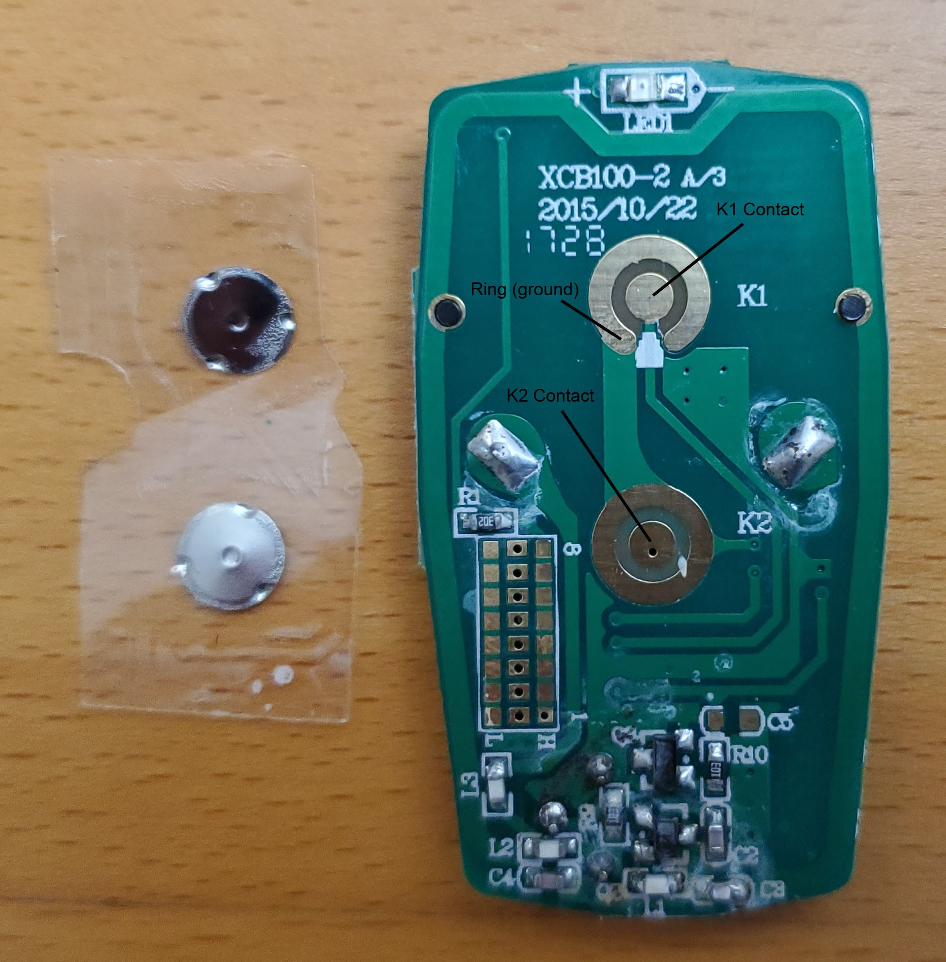
Use a small screwdriver to split open the plastic case of the keyfob near the key ring clip. Remove the circuit board and discard everything else, including the batteries. Transparent tape holds the two metal pushbutton in place. Remove the tape and discard the tape and pushbuttons.
-
6Solder 3 pin connector to K1 and K2 of keyfob
Place a drop of solder on the center of each pushbutton contact on the keyfob circuit board (labeled K1 and K2). Each contact also has a metal ring. Put a drop of solder on one of the metal rings. Take the one of the Micro JST 1.25 mm 3-pin connectors. It does not matter if it is male or female end, as long as the mating connector is used for the pushbutton switches. The connectors come with wires that are about 3.5 inches long. There is no need to cut the wires. It is a good length. Look at the picture for Step 11. It shows how the wires will emerge from the under side of the keyfob printed circuit board. Solder the red wire to the K1 center contact. Solder the yellow wire to the K2 center contact. Solder the black wire to one of the metal rings. Dress the wires to the right hand side. When the board is in place, the wires will be in the right position for gluing (next step).
![]()
-
7Position and glue keyfob
![]()
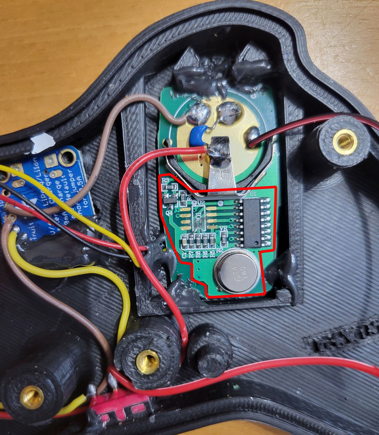
Top half of case. Study how the keyfob will be positioned into the case. The K1 and K2 solder connections will be pressed gently against the inside top of the case. A tiny clear LED at the top of the keyfob (top of photo in Step 6) should line up with a hole in the case. Hold the keyfob into position and then flip the case over to get a good idea of the LED alignment. You should see the LED through the hole in the outside of the case. Look at the photographs to see how the Micro JST connector wraps around the keyfob.
Use a thin piece of duct tape or electrical tape to hold the keyfob in position for gluing. Epoxy the top, sides and bottom of the keyfob. Not much glue is needed and the circuitry would rather not have too much epoxy on it. Note the red zone in the picture. If epoxy gets into this zone, gently wipe it off during the gluing, or gently scrape it off after the epoxy cures. Once the epoxy cures, carefully remove the tape and and epoxy one or two more spots. Put some epoxy on the Micro JST wires as they emerge from the back to the keyfob circuit board.
-
8Prepare charger board
Solder 3 wires to the LiPo charger board. Each wire should be about 5" long. Solder two to the middle two GND connections and the third wire to the BAT connection. The +5 v connection is not used. In the photograph I have used green wires for the ground and orange for the battery. Black wires are more commonly used for ground.
-
9Glue tactile switches into place
Bottom half of case. Check the fit of the tactile switches on the two switch mounts. See photo in Step 13. When the switches are properly in position, the switch leads should face the front and back of the mount. (The sides of the switch mount are raised.) Remove the switches, put some epoxy onto each of the two switch mounts and then press the switches into place. Try not to glue the front switch leads to the mount. Leave the switches undisturbed for an hour to let the epoxy cure.
-
10Glue slide switch into position
Top half of case. Work the slide switch into it's recessed position inside the case. Hold the slide switch in position and glue each flange inside the case. Keep the switch in place until the glue cures enough to hold the position, then give it at least an hour before testing the switch. Picture shows assembly to this point.
Adaptive wireless switch
Adaptive switches are often used by people with limited hand function. This switch looks like a game controller and uses a low cost keyfob.
Discussions
Become a Hackaday.io Member
Create an account to leave a comment. Already have an account? Log In.