Andrew Mitz
-
Very successful design
07/24/2024 at 11:14 • 0 commentsSince the start of this project I have assembled 5 of these wireless switches. The latest version is rugged and reliable. The range of operation is only about 4 to 6 feet, but that works well for my application. As the battery runs down, the range reduces.
I use 500 mAh batteries, but the controller will fit 1000 mAh batteries with no problem. I purchase fresh batteries every 4 years or so, but I actually do not know how long a battery will last.Assembly is somewhat tedious. The detailed instructions are very helpful.
-
Using heat-set threads for mounting posts
03/18/2024 at 17:03 • 0 commentsOne weakness of the existing design is that the mounting posts can break when being tapped, or the threads can be stripped during assembly. The best way to protect the plastic mounting posts is to use heat-set thread inserts. Note, this only works with thermoplastics. There is an expansion-type insert that can be used on other plastics.
I use McMaster-Carr part 93365A230. Carefully drill out the 4-40 thread holes in the mounting posts with larger and larger drill bits until you reach 9/64". Try to hit this size exactly (that is, buy a 9/64" bit). If you use other heat-set threads, drill to the specifications of those threads. Make sure the bottom of the heat-set thread just fits into the top of the hole. With a soldering iron (with a very clean tip), poke the tip into the heat-set thread and hold until the plastic gets soft. With a little push from the iron, the thread will advance smoothly into the hole. Lift the soldering iron off when the insert is completely inside the post. Have a small flat screwdriver handy to keep the thread from lifting up while you lift the soldering iron. There are some good demos in the Internet, so you can see how it works. -
Project complete
08/01/2020 at 12:46 • 0 commentsThe project is complete. A tiny tweak to the lower body case lip helps the case fit together without endangering any of the alignment posts. The USB charger board is held in place by the rear pins and the adjacent wall. The front pins (nearest the micro USB connector) are not used. Final STL files have been uploaded to print your own case.
-
Project files updated
07/10/2020 at 22:26 • 0 commentsBill of materials file deleted and replaced by listing of all components. Draft step-by-step file replace by full set of instructions.
-
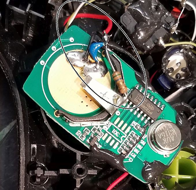
Capacitor to assure the controller triggers the receiver
07/05/2020 at 19:58 • 0 commentsI found two controllers that did not properly trigger the receiver. I saw a similar problem with a non-rechargeable controller I built earlier (see photo). The keyfob board is designed to work with coin cells. When you use a separate power source it lacks a low impedance RF pathway across the battery terminals. To solve this, I added a 1.0 uF ceramic capacitor across the keyfob battery terminals. The picture shows a capacitor with a 5.6 ohm resistor. You don't need the resistor. (The resistor was needed in that earlier design because I ran it on 6 volts, which was too high.) The capacitor solves the problem in the new controller. Some controllers will operate without the capacitor, but why take chances? The instructions have been updated to include the capacitor.
![]()
-
Draft assembly and BOM files have been posted
07/04/2020 at 02:02 • 0 commentsFiles now have preliminary assembly instructions and bill of materials.
Basic operation.In the chrg position, the controller is off and can be charged using a standard cell phone charger and a micro-USB cable. The charger LEDs will go from red to green when the battery is fully charged. In ON position, the battery is in use. The LEDs from the PowerBoost board should be visible: green when ON, but turns to red when the battery is low. The keyfob LED should light red when a button is pressed.
The intended receiver is an Adafruit
1096 Simple RF M4 Receiver - 315MHz Momentary TypeIt is built into my Raspberry Pi PlayVideo system
https://wordpress.com/page/arm22q13.wordpress.com/3369 -
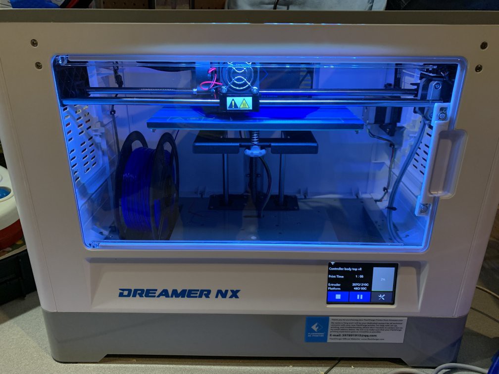
3D printer
07/03/2020 at 22:09 • 0 comments![]()
The 3D printer used for all the prototypes and production adaptive switches is the Flashforge Dreamer NX. Because the project was to aid disabilities, the use of the printer and materials were donated by two wonderful supporters of this project.
Adaptive wireless switch
Adaptive switches are often used by people with limited hand function. This switch looks like a game controller and uses a low cost keyfob.