The TMD-1 Instructable has been posted. Much of the information duplicates what you can find here but in addition the Instructable includes all of the files required to build a TMD-1 (STL, DXF, etc,).
For all of the vintage "toy" computers that I have made reproductions of one thing stands out, they all had excellent manuals. To that end I have created the TMD-1 Quick Start Guide, a small 10 page document that contains:
A brief description of what a Turing machine is.
A summary of TMD-1's characteristics.
An explanation of what the various parts of TMD-1 are and what they do.
What you should expect when you power-up TMD-1.
A step-by-step guide to writing and testing a simple TMD-1 program.
I don't know if it's excellent or not, but my hope is that this will be all a person needs to understand and use TMD-1. I'm going to try it out on a few people to see if they can start writing programs (without any help from me) . I have posted the guide as a Word doc to the the Files section.
This has been a very fun, exciting, and rewarding project for me. Fun because well, all my projects are fun or I wouldn't be putting so much time and effort into them. Exciting because I really loved the idea of TMD-1 and unlike my more usual "reproduction" projects this one was an original that allowed me to exercise my creative juices. Rewarding because the end result turned out so much better than I could have imagined.
I've been so consumed by all things Turing for the past two months that it's hard for me to judge if I have achieved my "easy to understand" goal. It's certainly easy for me to understand sure, but what about someone not as immersed in the subject as I am. When I get a chance to show TMD-1 around a bit I might be able to get a better sense of whether I hit the mark or not.
I'm a little more confident to think that I have accomplished the "simple to program" goal. I loved using the "tile" interface when I was making my demonstration programs. Development is very iterative with a quick load, run, test, fix cycle. While the single step function was added as a learning feature it sure works great as a debugging tool as well. So I'm going to pat myself on the back for "simple to program".
I wouldn't necessarily say that TMD-1 was "easy to build", I will say that it was pretty straight forward though. There is nothing too tricky about the build, just a fair amount of complexity to deal with.
Next Step
My plan over the next week or so is to create a TMD-1 Instructable. I'll post all the build files and details there and add a link to the Instructable here.
Welcome to TMD-1, the state of the art in Turing teaching technology.
Overview
To get started let's deconstruct the Tape and Finite State Machine Panels to take a look at the main components of the machine and find out what they do.
TAPE
Reset: When pressed will set all input area cells to '0', position the Head at the rightmost input area cell, set the current STATE to 'A', and set the Next Transition Step to READ.
Left: Move the Tape Head one cell to the left if after a Reset. If in RUN mode will make TMD-1 run slower. Can also be used to position the Head prior to running.
Flip: Flip the symbol at the current Head position. In conjunction with Left and Right allows you to setup "data" in the input area.
Right: Move the Tape Head one cell to the right if after a Reset. If in RUN mode will make make TMD-1 run faster. Can also be used to position the Head prior to running.
Tape Controls:
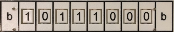
Tape: Turing machines are all about the tape. While some Turing machines have tapes that are infinitely long in one or both directions, TMD-1 has a more modest fixed tape length of ten cells. The left and rightmost cells have a special fixed symbol 'b' called an endmarker which can be read but not written on. The other eight cells comprise the "input area" of the Tape and can be set to either '0' or '1'.
Head: One lamp will be ON at any given time indicating the current position of the Tape Head.
FINITE STATE MACHINE
Transition Steps: The transition step to be executed next is highlighted. This is the step that will be executed when the PLAY button is pressed.
State Register: The current active state will be highlighted here. By definition the state 'A' will always be the starting state.
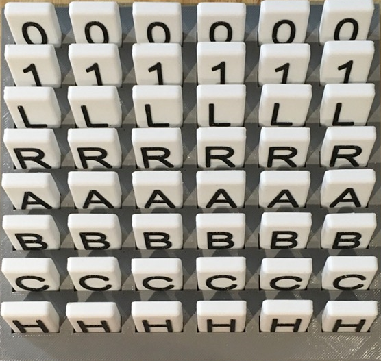
Transition State Table: This is where you "program" TMD-1 by defining the transitions between states. You do this by placing tiles in the blank spaces that are appropriate to the Transition Step row they are being placed in.
For WRITE row tiles are '0' and '1', for MOVE 'L' and 'R', and for GOTO 'A', 'B', 'C', and 'H'.
Transition Indicator: Once the READ step has been performed, the current active transition column determined by the combination of current state and symbol being read will be highlighted.
Finite State Machine Controls:
RUN - TMD-1 will run the program until the HALT state is reached.
STEP - Each time the PLAY button is pressed a Transition Step will be executed.
PLAY - Use the PLAY button to start the machine RUNning or to execute the Next Transition Step.
HALT - Will light up when TMD-1 has reached the HALT state.
On System Start or Reset
When the machine is first turned on or has just been Reset you should see:
This means that TMD-1 has been initialized with the following starting settings:
All cells in the input area have been cleared to 0s.
The Tape Head is set to the rightmost cell of the input area.
The State Register is set to the default starting state of 'A'.
The Next Transition Step to be executed has been set to READ.
In other words TMD-1 is ready to go.
Your First TMD-1 Program
With the "introductions" out of the way we are going to jump into the deep end and create our first Turing Machine Demonstrator program. The problem is simple:
Write a program to invert all of the symbols in the input area. So all 1s become 0s and vice-versa.
Let's get started.
Laying Some Tiles
Programming TMD-1 is as simple and filling in the State Transition Table with the provided tiles. Let's see how this works.
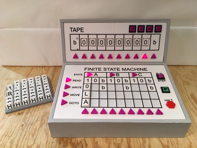
When that first READ is executed, the symbol read could be any one of '1', '0', or 'b'. Since we are in the 'A' state, we will have to fill in all three Transitions associated with those symbols and 'A'.
Starting with '1', since we are inverting we are going to want to WRITE a '0' to the cell. All of the remaining input cells to be processed are to the left of the current Head position so MOVE should be an 'L'. We will stick with 'A'' for the GOTO state, since there may be more 1s to process in the same way. With the '1' Transition column done:
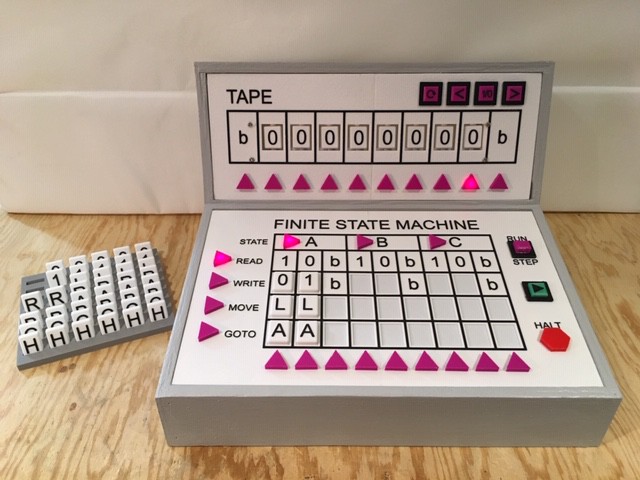
The '0' Transition will be very similar except we want to WRITE the inverted '1' symbol:
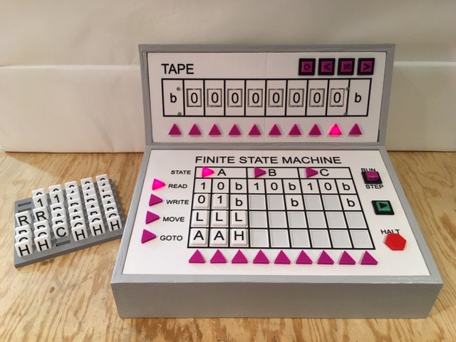
And finally if we encounter the 'b' symbol we know that the whole input area has been processed so just HALT. It doesn't matter what MOVE direction we use here:
So that's it. Our first program is finished, using only a single state to accomplish the task. But is the program correct? We should probably STEP through the first Transition to make sure everything is working as expected.
Slow and Steady
Using the STEP feature is a great way to debug a TMD-1 program.
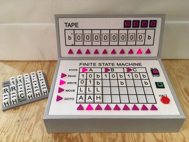
Before we can start testing the program we just "entered" we have to press the Reset button in order to "load" the State Transition Table into TMD-1's memory. Having done that, set the RUN/STEP toggle switch to STEP and press the PLAY button once:
We can see that the READ operation has selected the 'A0' Transition to execute which is correct since we are in state 'A' and the Head is on a '0' cell. The Next Transition Step has been set to WRITE. Check!
Press the PLAY button again:
WRITE was execute and the Head's cell has been update to a '1'. Next Transition Step set to MOVE. Check!
Press the PLAY button again:
Next Transition Step set to GOTO. Head has been correctly moved one cell to the left. Check!
Press the PLAY button one more time:
GOTO has Transitioned back to the 'A' state and is ready to READ the next cell. Check!
All is looking good. Time to RUN the program and see what happens.
Running
I pressed Reset again to reestablish my clean starting state and switched the RUN/STEP toggle to RUN. You will see at the beginning of the video that I used the Tape Controls to put a few 1s into the input area to get some good test data, being careful to position the Head back at the rightmost input area cell before pressing the PLAY button. Here is the result:
Your Next Program
Hopefully I've convinced you how easy it is to write a TMD-1 program. A good next step might be to extend the inversion program we just wrote.
If you consider the input area with its 0s and 1s to be a binary number, then what the inversion program does is to create what is called the 1s compliment of that number. The 2s compliment of a binary number is just the 1s compliment of the number to which a 1 is added (mathematically).
You have 2 whole unused states to add the 2s compliment functionality. Are you up to the challenge?
With all the testing I have been doing I'm convinced that the hardware and firmware (an Arduino Sketch) are solid and ready for prime time. So far I have written and successfully run TMD-1 "programs" to do the following:
3-State / 2-Symbol busy beaver
1s compliment of input area
2s compliment of input area
counting (ascending)
shifting (left) / multiply by 2
sorting all 1s in input area to the left
So I'm declaring the TMD-1 hardware officially finished.
I've been having a lot of fun "programming" my TMD-1. It's actually a pretty cool development environment. Just lay down the tiles in the state transition table, press reset to load the table into memory and initialize the machine, then press the Play button. STEP mode is extremely useful for "debugging" your program as you might expect. I can really see TMD-1 as an interactive tool for teaching Turing concepts.
I created a sorting program. It's purpose is to move all of the 1s to the left most side of the input area. This demonstration also show how you can use the controls on the Tape unit to reset a value in the input area and position the Head prior to running the program. Here it is in action:
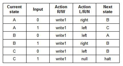
This next one I didn't program myself. The state transition table for this 3-state "busy beaver" is pretty well known:
I'm not sure how long it would have taken me to figure this out for myself. Here is the result:
All in all I'm really happy with how TMD-1 is working.
One might think having an eight cell "input area" would limit the tasks TMG-1 could perform. In actual fact I could not find any interesting programs that could not be run in eight or less cells on an unbounded tape. What does interesting mean? Well the program would have to do something non-trivial (something more than writing a single symbol to the tape) and then stop. Stopping is important because there is nothing interesting about a program wondering down a tape to infinity (at least after the first millennia or so).
To be brutally honest, there is only one program that runs on on a 2-symbol (assume the b is not used)/ 3-state Turing machine that is truly interesting, the "busy beaver". The busy beaver "game" consists of designing a halting, binary-alphabet Turing machine which writes the most 1s on the tape, using only a given set of states, in this case 3-states. By definition a busy beaver program running on TMG-1 is prohibited from using the endmarker. symbol I won't spoil the ending but this programs runs fine in eight cells.
In actual fact implementing TMG-1 as an Linear Bounded Automata suddenly makes it a lot more interesting and fun. Being able to determine the beginning and end of the input area is key. With this little LBA we will be able to:
Treat the input area as a binary number and find the one's compliment. (Making the input/tape alphabet 0 and 1 was not by accident in this case, although by convention this is often the case. ;-)
Find the two's compliment of the "binary" number in the input area.
Count in binary (ascending and descending).
Sorting. Move all the 1's in the input area to the right or left.
Shift the input area one cell to the right or left (multiply / divide by 2).
Make a Cylon eye with head lamps ;-)
You get the idea. As an LBA the Turing Machine Demonstrator is a much more capable teaching tool even with only eight cell for the input area.
Testing went well. On the hardware side I only had two incidents with crossed wires from the Transaction Table Reader to the Arduino and a single broken LED that needed replacing. Otherwise the build was pretty solid.
Coding also went faster than expected. I'm still tweaking the UI a little but as you can see in the demo that follows IT WORKS (I'm so happy).
Without further adieu here is TMG-1 in action counting to ten. Basically the head adds one to the number already present in the input region (between the b markers) then goes back to the beginning and repeats.
How fast the machine works in RUN mode is one of the things I'm still playing around with. I want people to see what is going on with each step but not get too frustrated waiting for things to happen. Maybe TMD-1 should RUN faster leaving the learning to STEP mode. UPDATE: I have made a change so that you can now press the left and right arrow buttons on the Tape Panel when in RUN mode to decrease or increase the running speed.
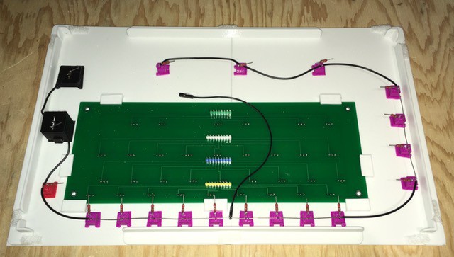
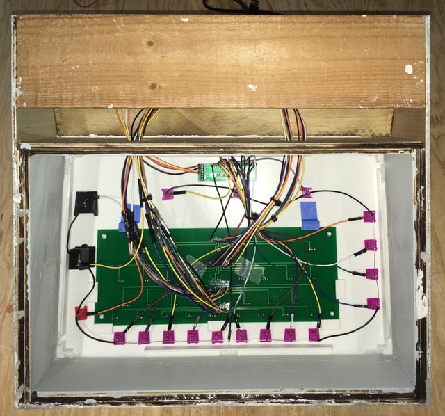
As with the Tape Panel I started by wiring all of the ground leads together for the LEDs and buttons then added a jumper so I could attach the ground(s) to one of the Expander's extra GND pins.
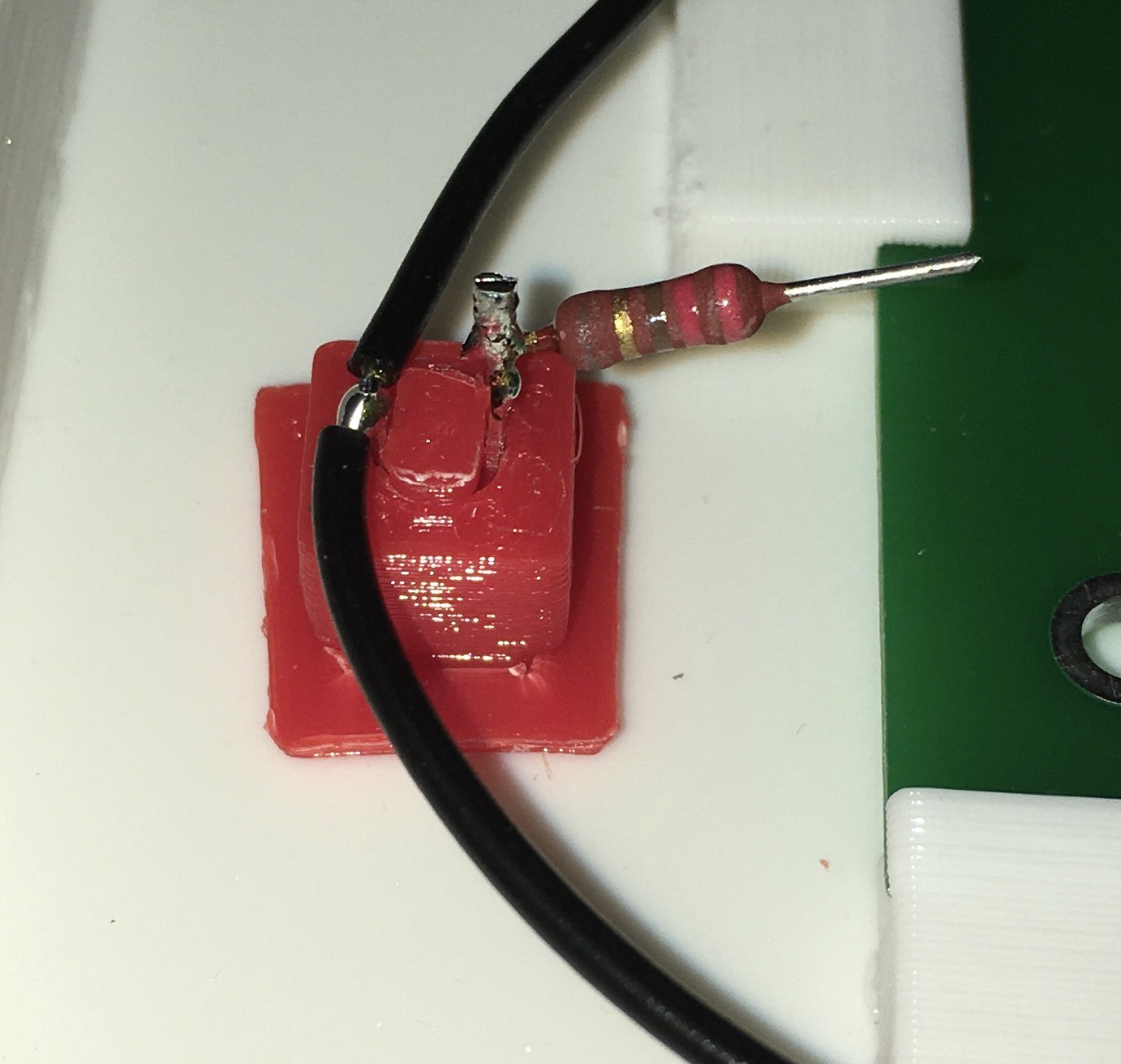
I added limiting resistors to all of the lamps.
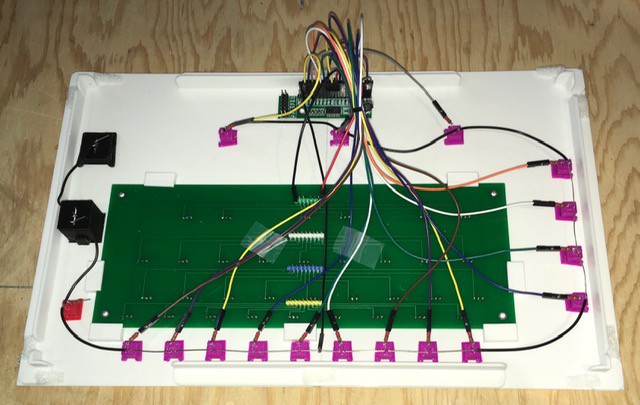
Then I mounted a second Expander PCB to the back of the Finite State Machine Panel with two sided tape and connected all 16 of the purple status lamps to it. I had to change the I2C address for this board so it would not conflict with the first. There are jumpers for this.
 Michael Gardi


 State Register: The current active state will be highlighted here. By definition the state 'A' will always be the starting state.
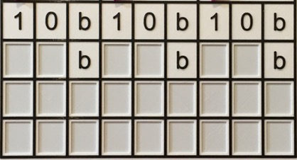
 Transition Indicator: Once the READ step has been performed, the current active transition column determined by the combination of current state and symbol being read will be highlighted.