Michael Gardi
-
Tape Panel Wiring
08/16/2020 at 14:11 • 0 commentsWire Wrangling
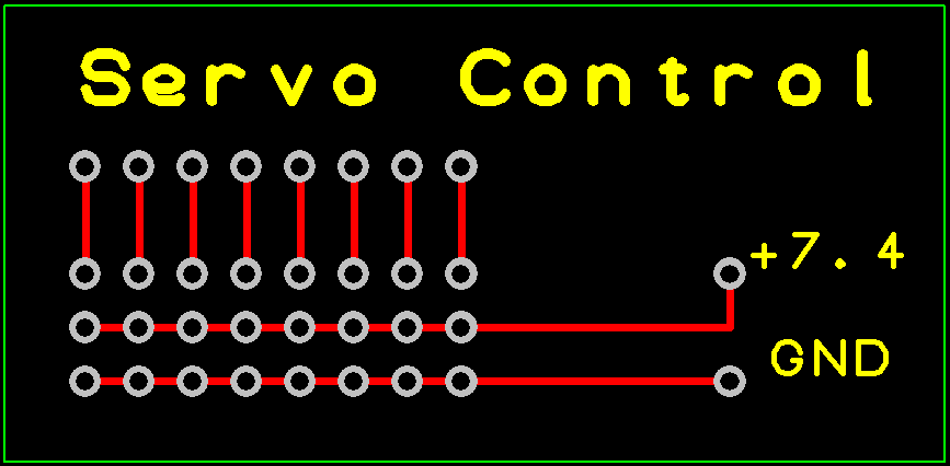
At the same time that I was having the Transition Table Reader board made I had a small PCB done to help wrangle the wires from the eight servos.
![]()
I just added headers to allow me to plug the servo connectors into the board with the PWM signals brought out.
Not Enough Pins
Now you would think that since I am using an Arduino Mega there would be enough I/O pins to go around. The Mega has 54 I/O pins plus the 16 Analog pins can be used as digital I/O for a total of 70! Well it turns out I need 74 in total. The breakdown:
- 27 outputs for LEDs
- 33 inputs for Hall Effect sensors
- 8 outputs for Servos
- 6 inputs for buttons and switches
I could have used a Charlieplexing Matrix for the LEDs and a Keyboard Matrix scheme for the sensors but that would have made my programming job that much harder.
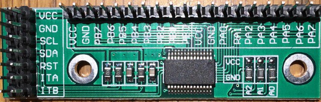
Instead I chose to use a couple of 16 Channel GPIO Expanders based on the MCP23017 part.
![]()
I'll use one for the 10 LEDs and 4 buttons on the Tape Panel, and the other for all 16 LEDs on the Finite State Machine Panel. Using these also has the advantage of "localizing" some of the wiring making for a neater job. It's also nice that they have extra VCC and GND pins in addition to doubling up on the control pins making wiring easier.
Wiring the Tape Panel
I started by joining all of the ground leads together for the LEDs and buttons then added a jumper so I could attach the grounds to one of the expander's extra GND pins.
![]()
To the LED anodes and the normally OFF terminal of the push buttons I attached jumper cables with female connectors to mate with the expander. I also added 220 R limiting resistors to the LEDs.
![]()
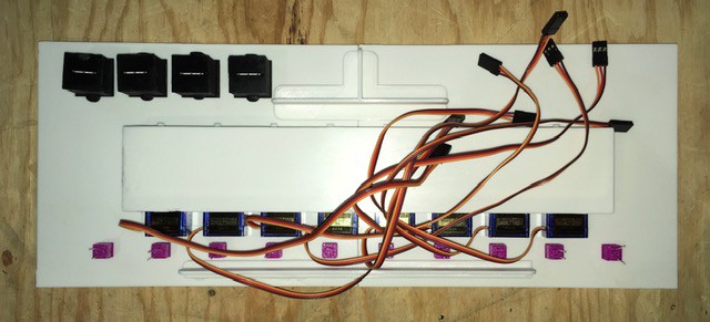
I mounted the Servo Control And Expander PCBs to the inside of the Tape Panel Box part of the frame using two sided tape.
![]()
The following connections were made:
From To Servo 3 pin connectors from left to right. Servo Control left to right (middle to edge of board). Make sure that the leads have the proper orientation. LEDs from left to right. Extender Pins: PA7, P A6, PA5, PA4, PA3, PA2, PA1, PA0, PB0, PB1 Move Right Button Extender Pin: PB7 I/O (Flip Bit) Button Extender Pin: PB6 Move Left Button Extender Pin: PB5 Reset Button Extender Pin: PB4 Tape Panel: GND Extender Pin: GND Servo Control Pin: VCC Extender Pin: VCC Servo Control Pin: GND Extender Pin: GND Connecting to the Arduino
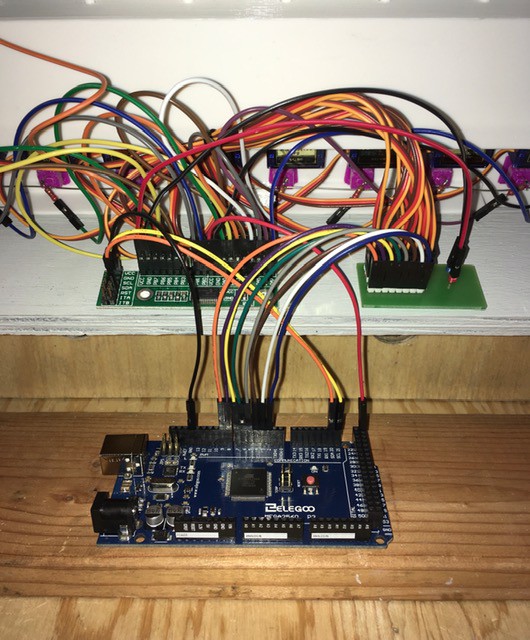
I mounted the Arduino below the Tape Panel boards to a reinforcing cross bar that I had added to the console again using two sided tape.
![]()
The following connections were made:
From To Servo Control PMW pins left to right. Arduino Pins: 2, 3, 4, 5, 6, 7, 8, 9 Extender Pin: GND Arduino Pin: GND Extender Pin: VCC Arduino Pin: VCC Extender Pin: SCL Arduino Pin: SCL (21) Extender Pin: SDA Arduino Pin: SDA (20) Done Wiring
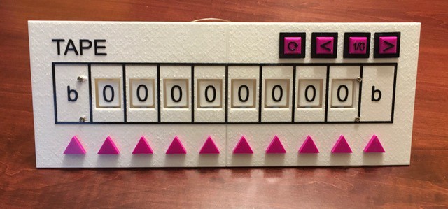
That's it. The Tape Panel is completely wired up and ready for testing.
-
"Console"idating the Panels
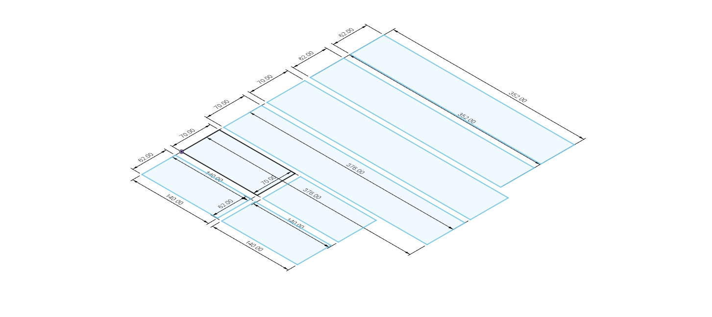
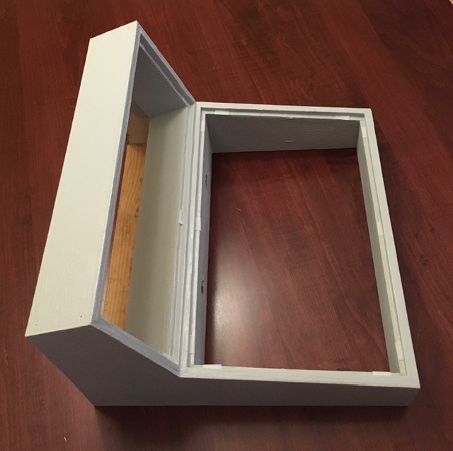
08/14/2020 at 21:47 • 0 commentsWithout going into a lot of details, I designed the TMD-1 console. I created the following DXF files.
Tape Panel Box
![]()
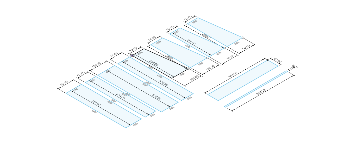
Finite State Machine Panel Box
![]()
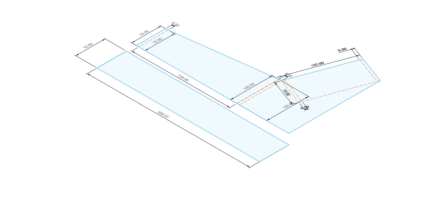
Console Frame
![]()
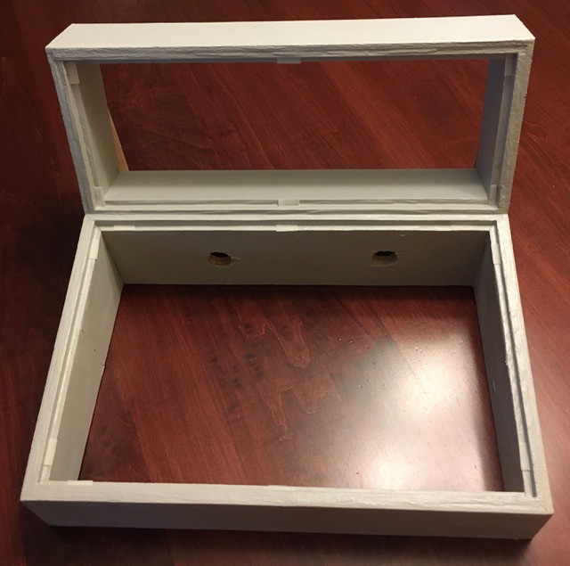
I laser cut them from 6 mm plywood. Once assembled I painted the whole console a light gray color.
![]()
![]()
You can see in the above photos where I added some Velcro to hold the panels in place.
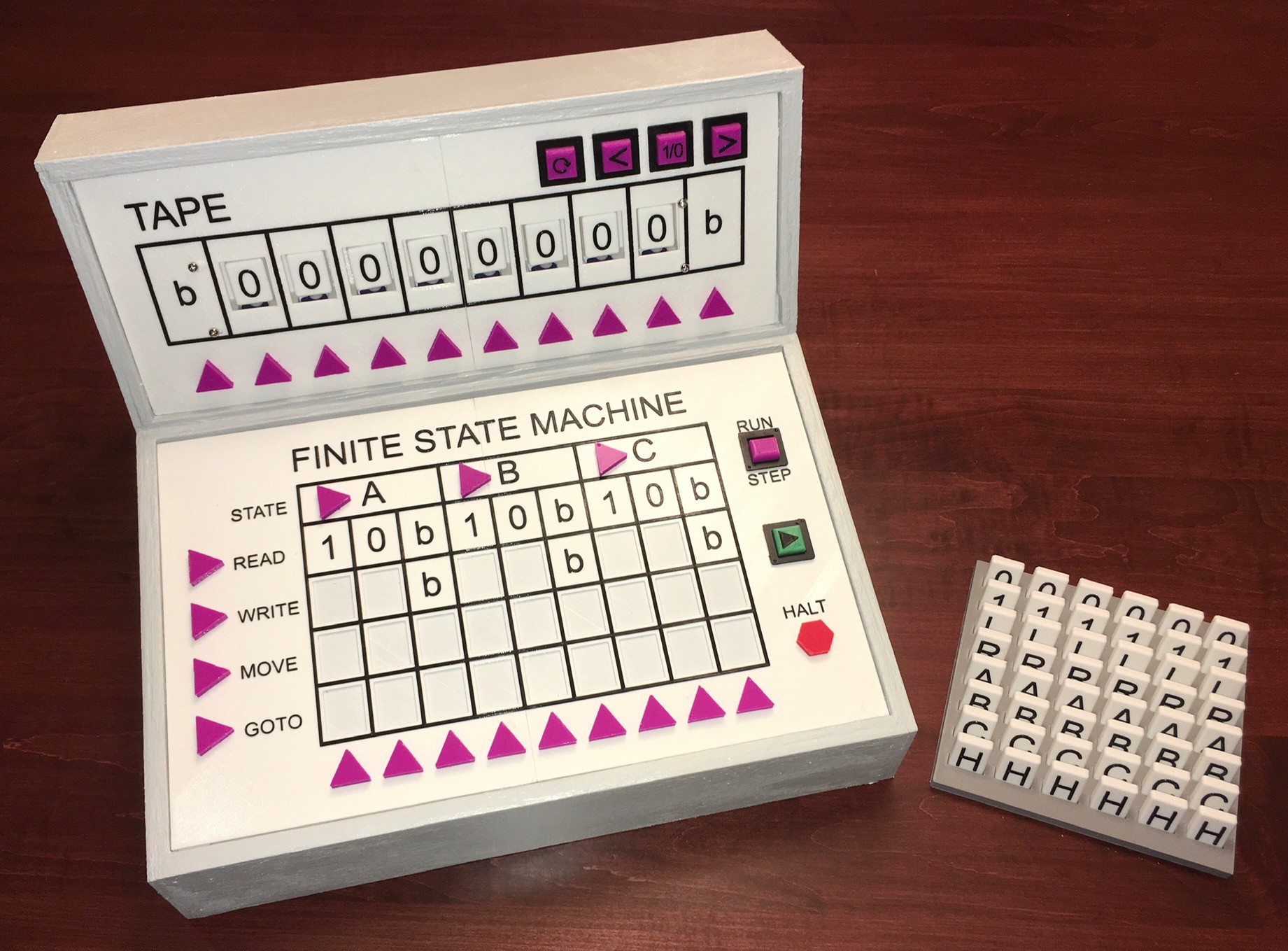
While there is still a great deal of wiring and programming work to do, this is pretty much what the final project will look like.
![]()
In this photo you can also see the finished "programming" tiles and a rack I made to hold them. On to the wiring.
-
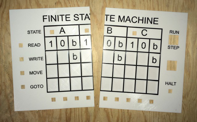
Finite State Machine Panel Assembly
08/14/2020 at 14:19 • 0 commentsLike the Tape Panel the Finite State Machine Panel was printed in two parts.
![]()
Here I also printed some braces and used some gel superglue along the edges and to attach the braces.
![]()
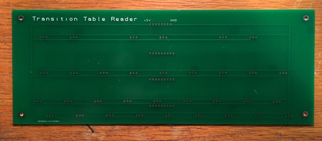
Preparing The Transition Table Reader
The PCB I designed for this arrived this week.
![]()
I have to admit this is version 2. The first board was too big. I had failed to allow enough clearance for the lamps and switches that will surround it. Also I found that the .05 pitch spacing for the TO-92 leads was a bit too challenging for my soldering skills, so I spread the leads out to .1 pitch in this version. Live and learn I guess. Costly lesson though.
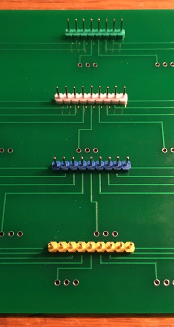
First I installed the headers that will bring out the signals for the 33 Hall Effect sensors. These are mounted on the back of the board. Once soldered, trim the short leads on the front of the board as close as possible to the PCB.
![]()
Next I started installing the sensors. There are a couple of things I had to be careful of here. Since I wanted the sensor to lie flat on the PCB I needed to make a 90 degree bend in the leads. It was also important to do this consistently for all sensors so I made a little jig.
![]()
The idea is to lay the sensor into the slot as far up as it will go.
![]()
And here is the second important thing. The sensor must be "face up". That is to say the face with the two facets visible on the left and right and the lettering must be visible. Holding the sensor firmly in place, bend the leads back 90 degrees.
![]()
The outer leads can then be spread out slightly from the center lead, inserted into the front of the board, and soldered in place.
![]()
Repeat 32 more times.
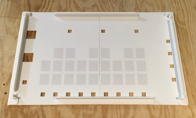
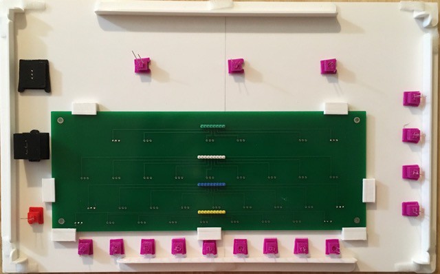
Mounting the Transition Table Reader
The Transition Table Reader is mounted on the back of the Finite State Machine Panel. The Hall Effect sensors must be carefully aligned with the shallow indentations where the tiles will be placed so that they can get a good read on the embedded magnets.
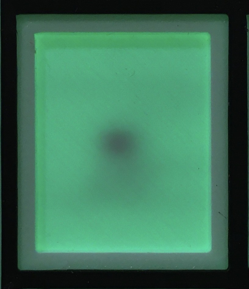
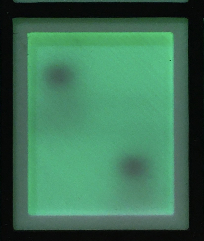
I found that the easiest way to do this was to hold the Transition Table Reader board roughly in place behind the Finite State Machine Panel while shining a bright light through the PCB from behind. You will be able to see the "black dots" of the sensors through the thin floor of the tile cutout areas. For the top two rows the single "dot" should be in dead the center of the tile cutout areas.
![]()
The last row has two dots for each cutout that should be diagonally arranged at equal distances from their corresponding corners in the cutout area.
![]()
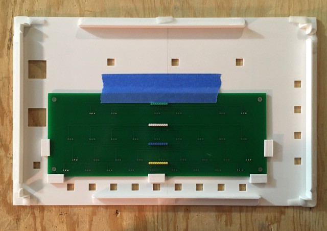
When everything is lined up tape the PCB in place. (NOTE: This process is much easier if two people are involved.)
I printed some brackets to hold the Transition Table Reader board in place.
![]()
Carefully go around the PCB replacing the tape with the brackets that get glued to the back of the Finite State Machine Panel.
![]()
Almost done in this photo.
Add the Switches and Lamps
Install the lamps and switches as shown in the next two photos.
![]()
![]()
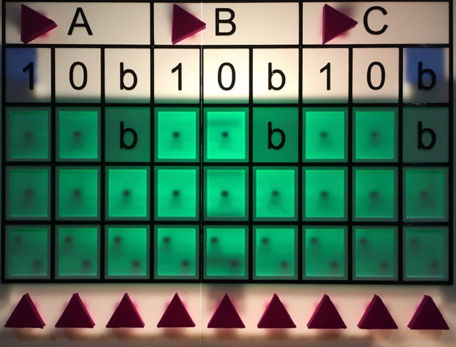
One final sensor alignment check. Looking good!
![]()
And now that's the Finite State Machine Panel ready to be wired into the rest of the project.
-
The Finite State Panel
07/29/2020 at 16:50 • 0 commentsThe Finite State Machine Panel will hold the transition table input area. In addition:
- numerous lamps will highlight the current "state" of the machine.
- a slider switch will be added to allow the user to toggle between "Run" and "Step" modes.
- there will be a "Play" button to start or step the machine.
- a special lamp will indicate when the machine has entered the HALT state.
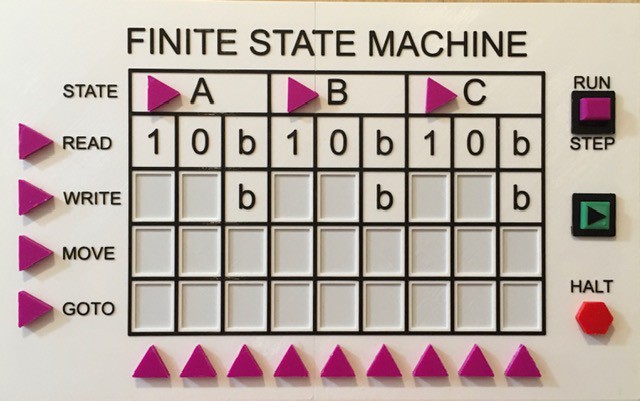
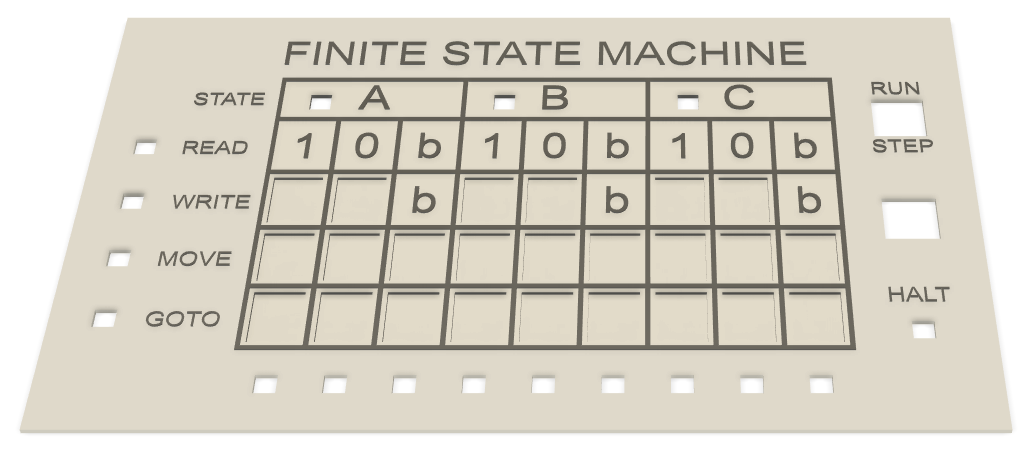
It looks like this:
![]()
As with the Tape Panel the controls have been designed specifically for this project.
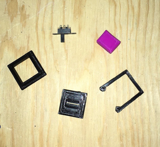
Slider Switch
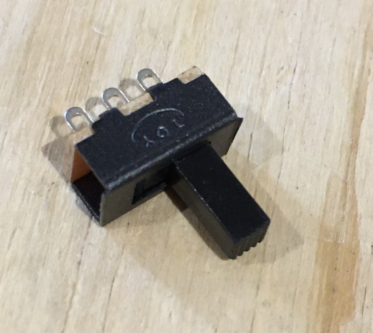
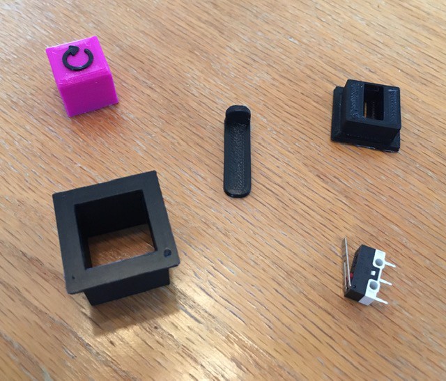
A slider switch will drop into the top right corner of the panel with labels RUN and STEP. It is simply a standard miniature slider switch (Amazon: uxcell® uxcell20Pcs 2 Position 3P SPDT Panel Mount Micro Slide Switch Latching Toggle Switch) with a custom 3D shell to give it a "look" consistent with the rest of the project. Here are the parts:
![]()
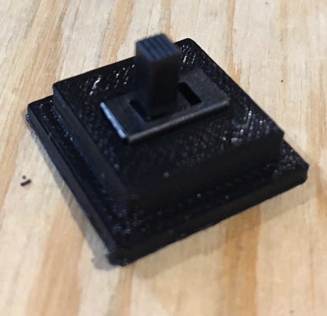
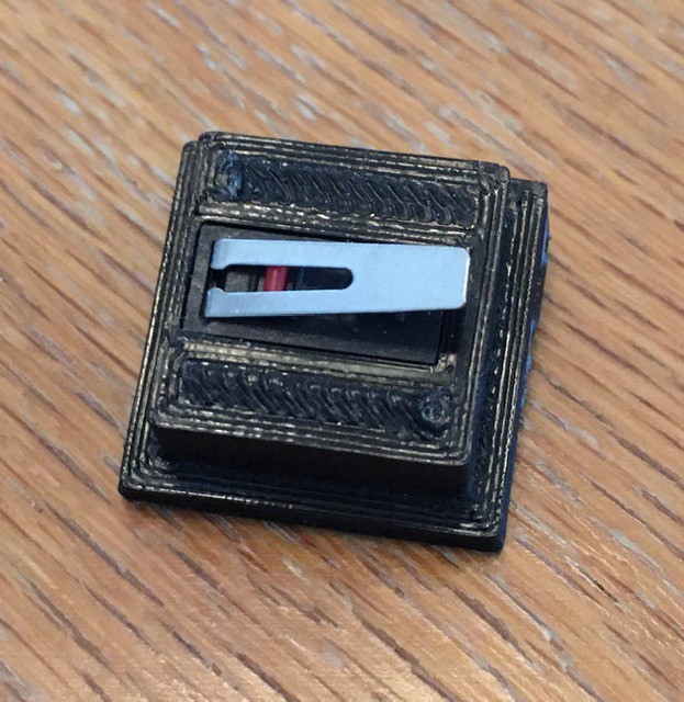
Start the assembly by cutting off the two top plate mounting holes from the switch then sliding the switch into the base piece as far as it will go. You might need a bit of glue to hold it in place.
![]()
![]()
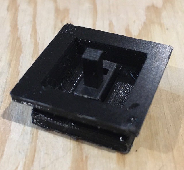
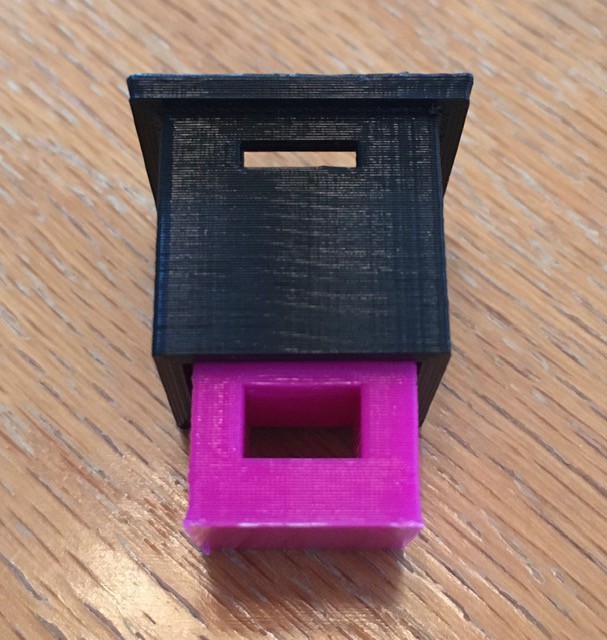
Next attach the base piece to the bottom of the console mounting piece. I used a small amount of glue to hold it firmly in place.
![]()
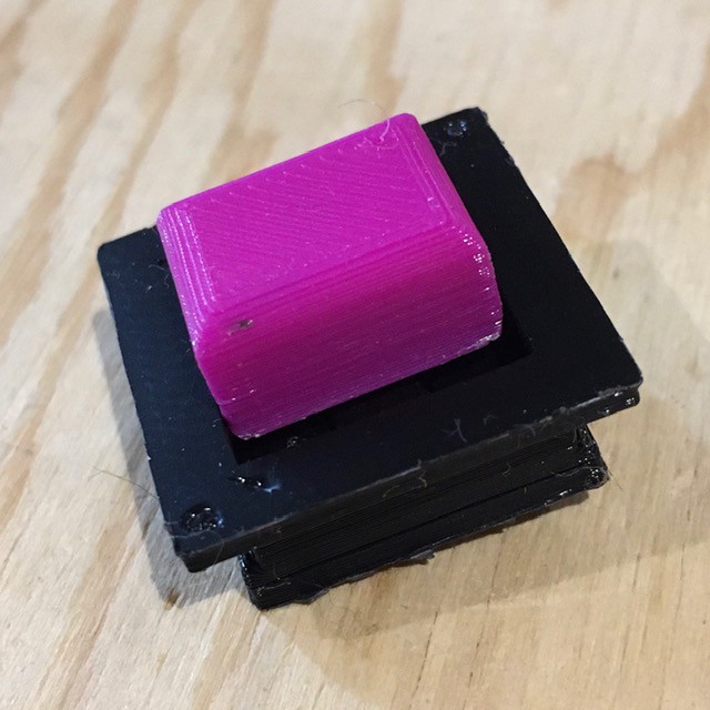
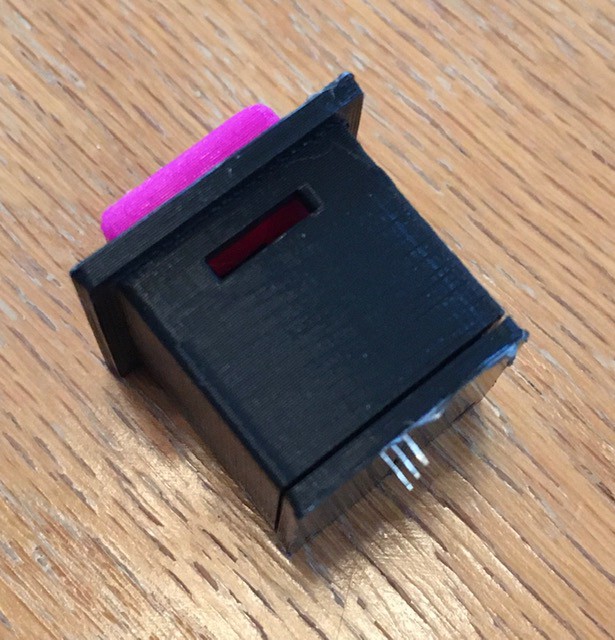
Finally attach the slider to the shaft of the switch. Again apply a drop of glue to hold it in place.
![]()
Don't forget to save the C clamp (pictured in the first photo) to hold this switch in place when mounted onto the panel.
Play Button
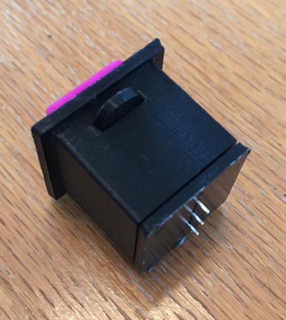
Exactly the same is the buttons used for the Tape Panel but with a slightly different look.
![]()
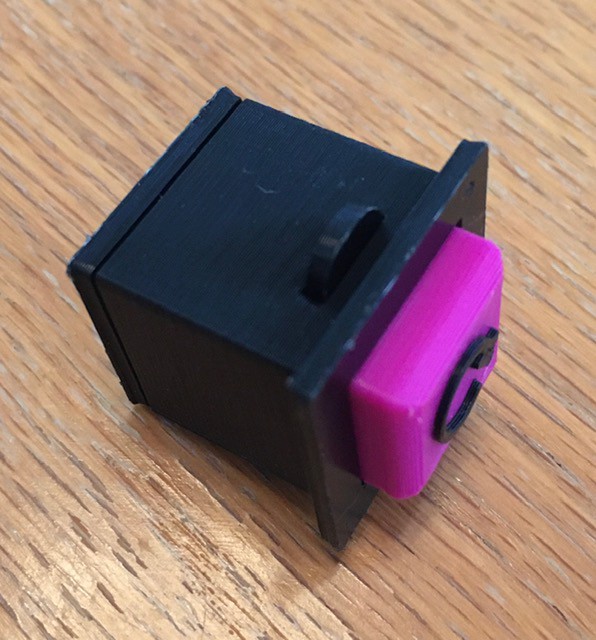
Halt Lamp
Same design as the indicator lamps on the Tape Panel but with a different diffuser design.
![]()
Next Steps
When the transition table reader board PCB arrives and I've had a chance to verify the alignment of the hall effect sensors with the input areas, I'll start printing the Finite State Machine board.
-
The Finite State Machine
07/28/2020 at 13:47 • 0 commentsThe core of a Turing machine is the Finite State Machine, a finite set of instructions that, given the state the machine is currently in and the symbol it is reading on the tape (symbol currently under the head), tells the machine how to transition to the next state of the computation. These Finite State Machines are usually described in one of two ways. As state transition diagrams:
![]()
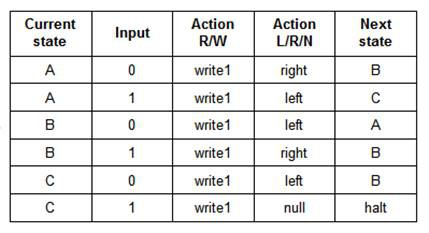
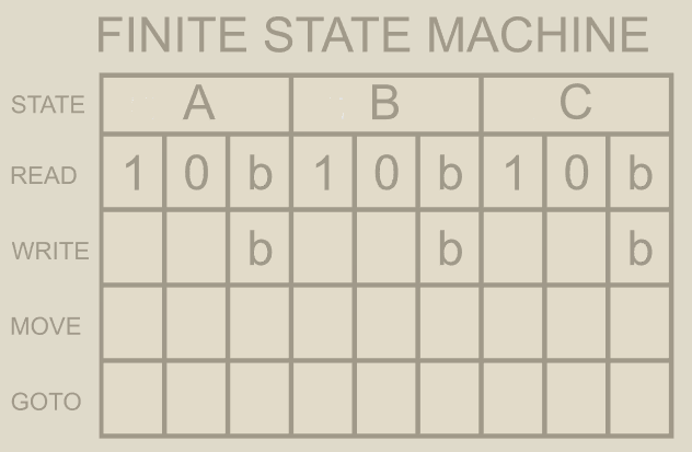
or as state transition tables:
![]()
Both of the above describe the same 3-state 2-symbol "busy beaver" program.
When building a Turing Machine, these definitions must somehow be manifested in a way that the machine can understand them. I have seen these state transitions encoded onto paper tape or expressed as pegs on a 2-dimensional board. Since this project is supposed to be a Turing Machine Demonstrator I wanted this "translation" to be as simple as possible. Then it struck me, "What if the state transition table and the Finite State Machine input were one in the same?".
State Machine Setup
So this is what the input area for TMD-1 will look like, a state transition table.
![]()
The blank boxes in the table above will have shallow rectangular depressions into which appropriately labeled "tiles" can be set: 1/0 for Write, L/R for Move, and A/B/C/H for Goto. TMG-1 will be able to "read" these tiles to determine the definition of the state machine. I'm calling this my "Azul" interface based on the name of the popular tile based board game.
Reading Tiles
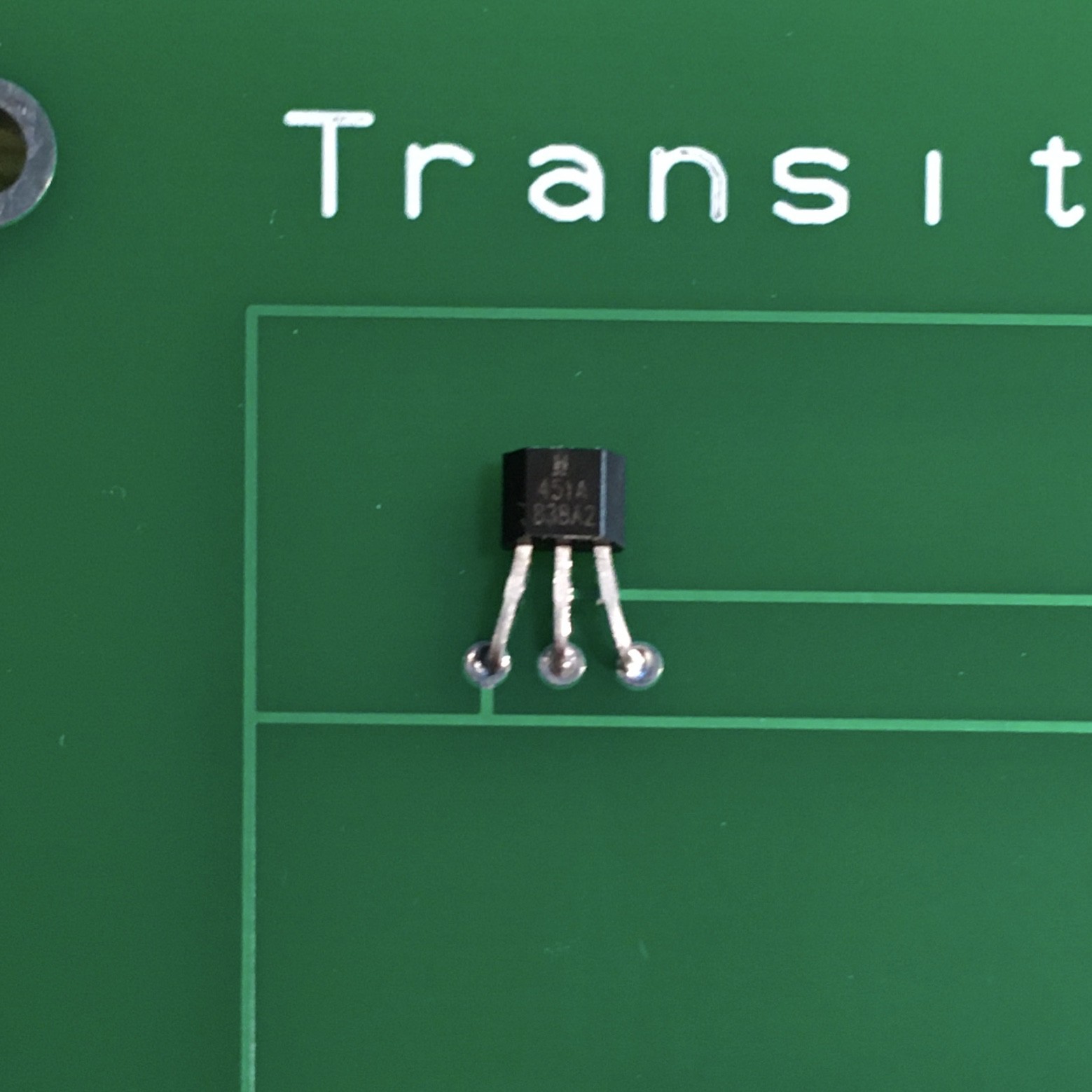
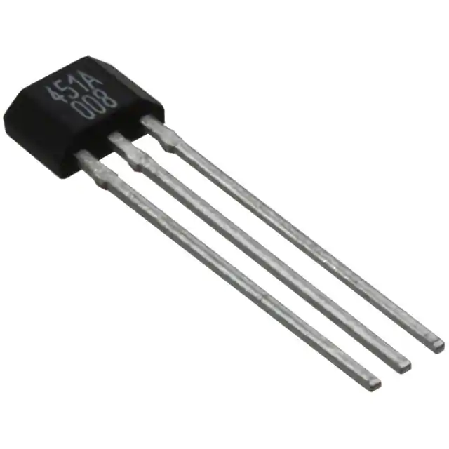
Once I determine how I wanted the Finite State Machine input to work, I had to figure out how to make it work. My first idea was to use magnetic reed switches, but I had been looking for an excuse to play around with Hall Effect Sensors. So I ordered some SS451A Omnipolar Magnetic Switches from Digi-Key.
![]()
I guess I shouldn't have been, but when they arrived I was surprised at how small these components were. I chose the omnipolar part because I didn't want to have to worry about the polarity of the "triggering" magnets.
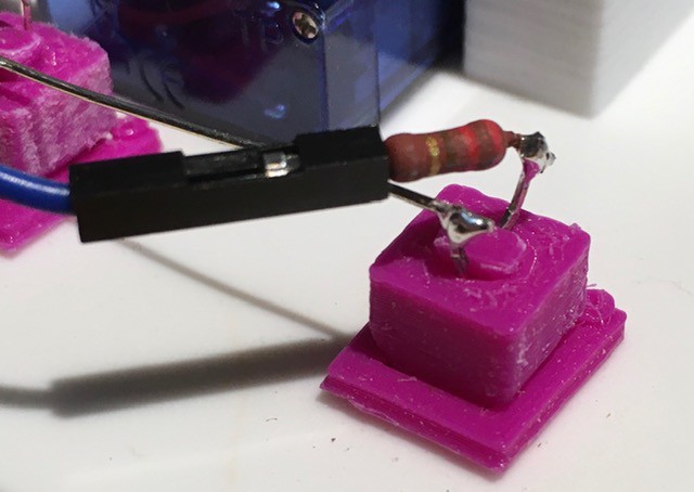
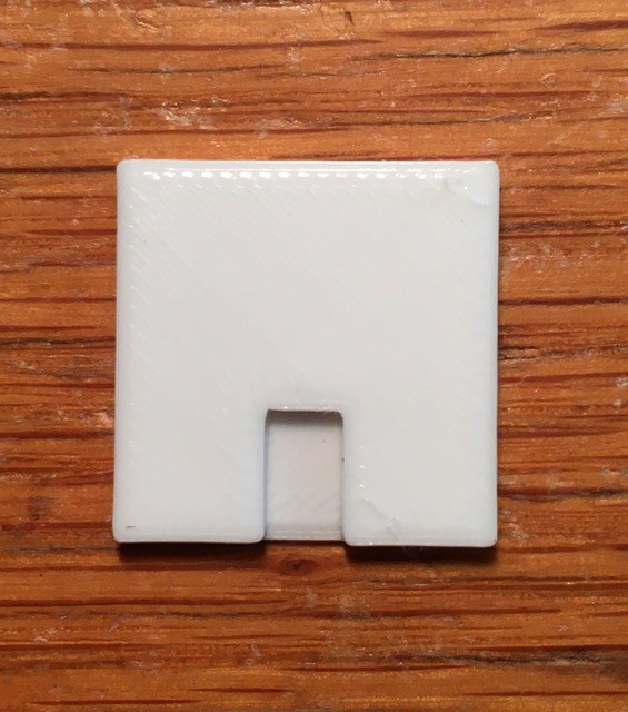
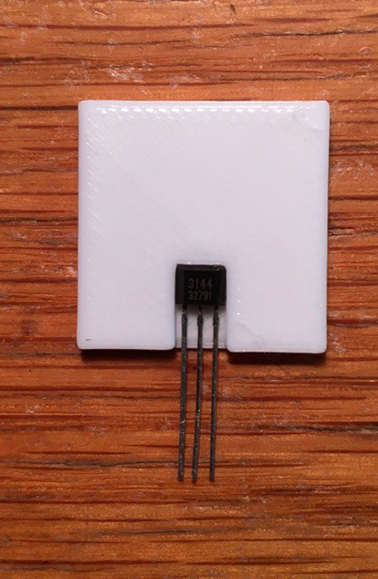
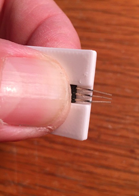
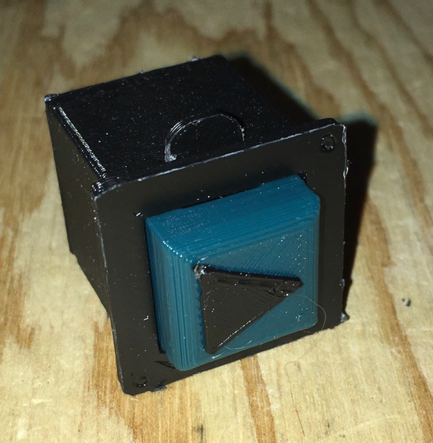
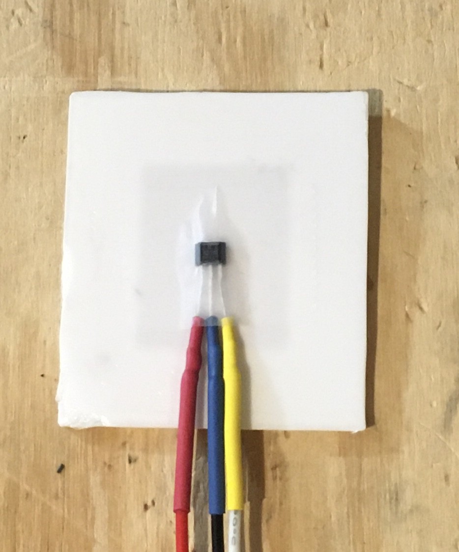
I setup a test. First I secured one of the sensors to the back of a small panel that I printed to represent a tile input square on my state machine.
![]()
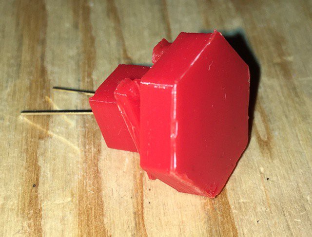
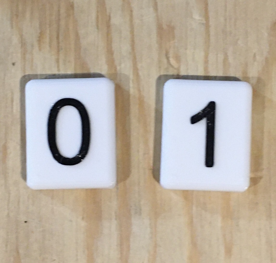
I connected this to an Arduino so that when the sensor was triggered an LED would light. Then I printed a couple of test tiles.
![]()
The tile with the "1" has a small 3 mm x 1.5 mm magnet embedded .6 mm from the bottom and centered in the tile, while the "0" tile has no magnet. Here is my first test:
Testing showed that the hall effect sensor can clearly be triggered by some very small magnets embedded into the tiles. Furthermore I found that the magnet must be lined up within a few millimetres of the central axis if the sensor. This is a good thing because it means that multiple sensors can be embedded within a small area (the tiles are only 20 mm x 25 mm) without the risk of interfering with each other.
Tiles will be identified based on their row and "magnetic" signature. So tiles placed in the Write row will be considered to a 0 or 1 based on the absence or presence of an embedded magnet. Similarly the Move row will assume the placement of R and L tiles. The Goto row must recognize four different tiles (A, B, C, and H) so two magnet positions will be used to create four unique identities.
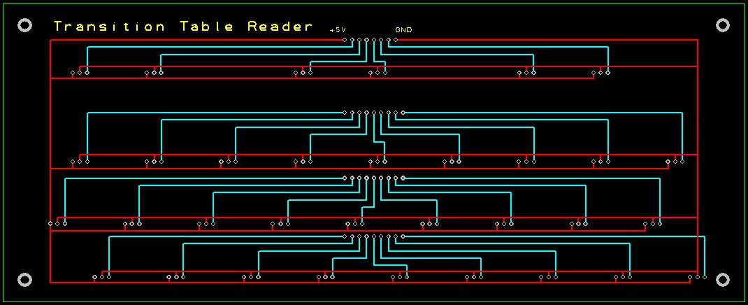
Since the parts themselves are so small and to ensure that they line up correctly with the input squares on the Finite State Machine transition table I created a PCB "reader" board.
![]()
This will be mounted directly below the input area of the transition table. It should be back from the fab in a few days or so now.
So the user will be able to "program" TMD-1 by simply using tiles to "fill out" a state transition table for the Finite State Machine. I don't think it gets much easier than that.
-
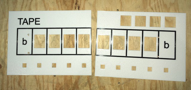
Tape Panel Assembly
07/27/2020 at 20:27 • 0 commentsThe Tape Panel print went well. I can't say enough about the Hilbert Curve Top Layer infill option in PrusaSlicer for getting a nice even looking matte finish.
![]()
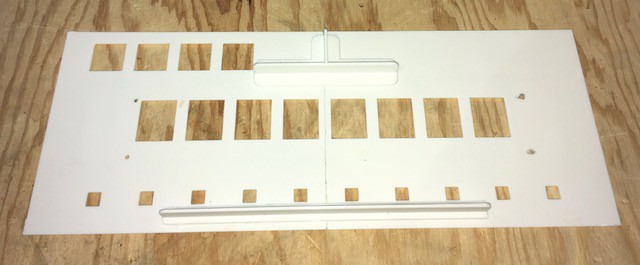
As you can see I had to print this in two pieces so the first order of business is to connect them together. I printed some braces to assist with this task. I use some gel superglue along the edges and to attach the braces.
![]()
Next I installed the Flip-Byte unit to the panel with four 3 mm x 10 bolts. The holes in the Flip-Byte are sized to self thread.
![]()
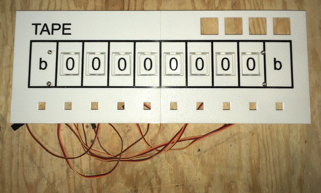
Then it's a simple matter of adding the control buttons and the Tape Head current position lamps.
![]()
![]()
That's it the Tape Panel is ready to be wired into the rest of the project.
![]()
-
The Tape Panel
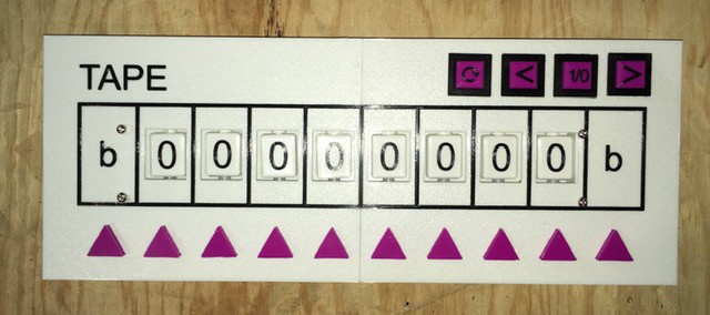
07/26/2020 at 02:01 • 0 commentsThe Tape Panel will hold the Flip-Byte and implement the Tape Head. In addition some buttons will be added to allow the user to reset the tape to a default state and to modify the bits and starting head position on the tape prior to running the machine should they choose. It looks like this:
![]()
So while I wait for the actual Tape Panel to finish printing I thought that I would talk about the controls.
Buttons
The tape control buttons will go into the four spots on the upper right of the panel. Rather than buying "off the self" I decided to design my own buttons so that I could coordinate the look with the numerous panel mounted lamps that will be used for this build. Anyone that has seen some of my other work will not be surprised by this.
So we are talking about a simple push button switch here that I built around a small micro switch (Amazon: Gikfun Micro Switch Long Hinge Lever (Pack of 20pcs) for Arduino EK1713) that I had lying around. Here are the mostly printed parts:
![]()
Assembly is pretty straight forward. Start by sliding the micro switch into the base piece making sure that the lever actuator does not extend past the edge of the base (there is one right and one wrong way to do this).
![]()
Next slide the button into the console mounting piece. Make sure that the slot on the button is aligned with the smaller slot at the top of the shaft.
![]()
Now attach the base piece to the bottom of the console mounting piece. I used a small amount of glue to hold it firmly in place.
![]()
Finally (for now) slide the locking tab into the slot at the top.
![]()
This will keep the button from popping out and when it is time to mount the button on the panel it will serve to hold the button assembly in place on the panel.
![]()
This is my "Reset" button. More to come.
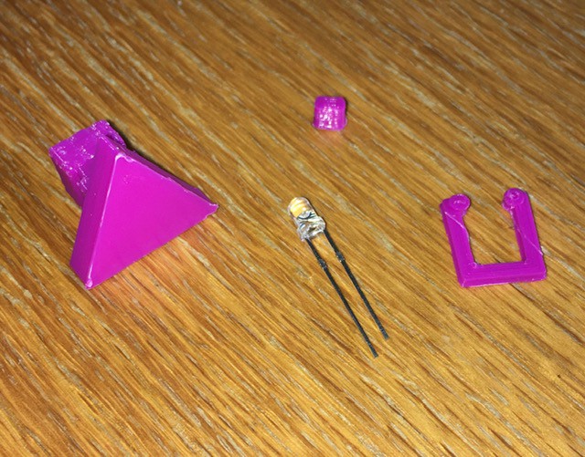
Lamps
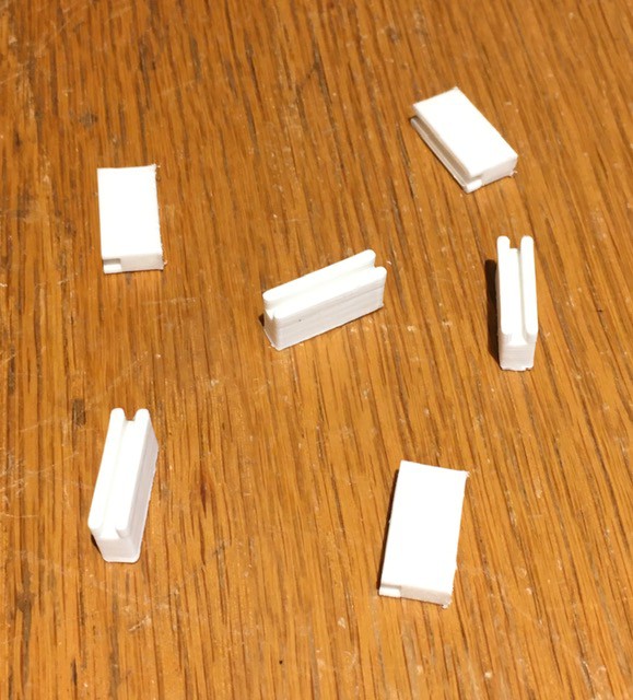
Since the Tape itself is fixed it means that the Tape Head has to move. There is a spot under each cell of the tape for a lamp that will indicate the "current" position of the Tape Head. The lamps are just simple white high intensity 3 mm LEDs (Amazon: Gikfun LED Lamps 3MM White Color White Light Super Bright for Arduino (Pack of 100pcs) AE1124) with a custom 3D printed housing. Here are the parts:
![]()
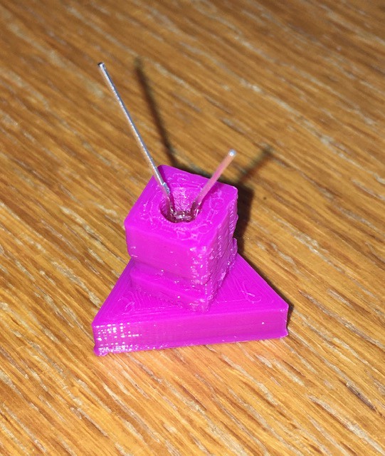
Nothing to the assembly. Start by sliding the LED into to the hole at the base of the lamp as far as it will go. I bend the leads slightly apart to make the next part easier.
![]()
Then press the small plug into the hole keeping the leads separate. This will hold the LED firmly in place.
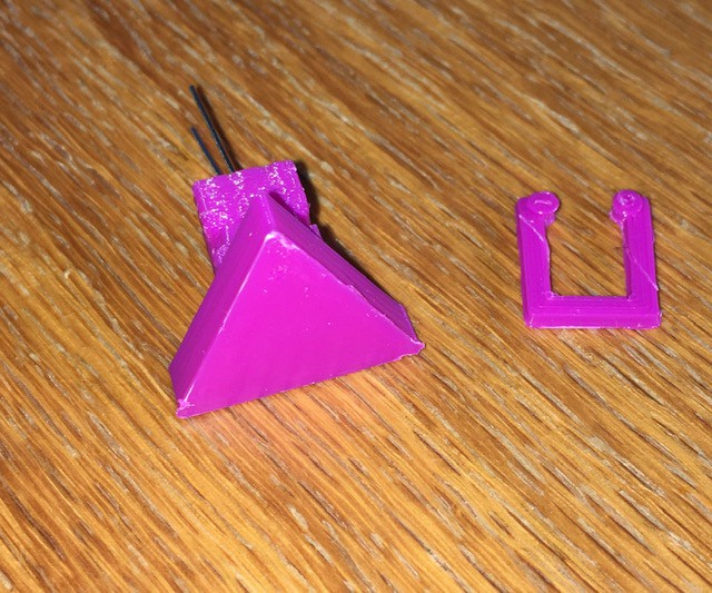
![]()
And that's it. When it comes time to mount the lamp to the panel the small C clamp pictured below will hold it in place.
![]()
So when the panel is finished printing in about 14 hours or so, all will be ready for the final Tape Panel assembly.
-
The Tape Implementation (Continued)
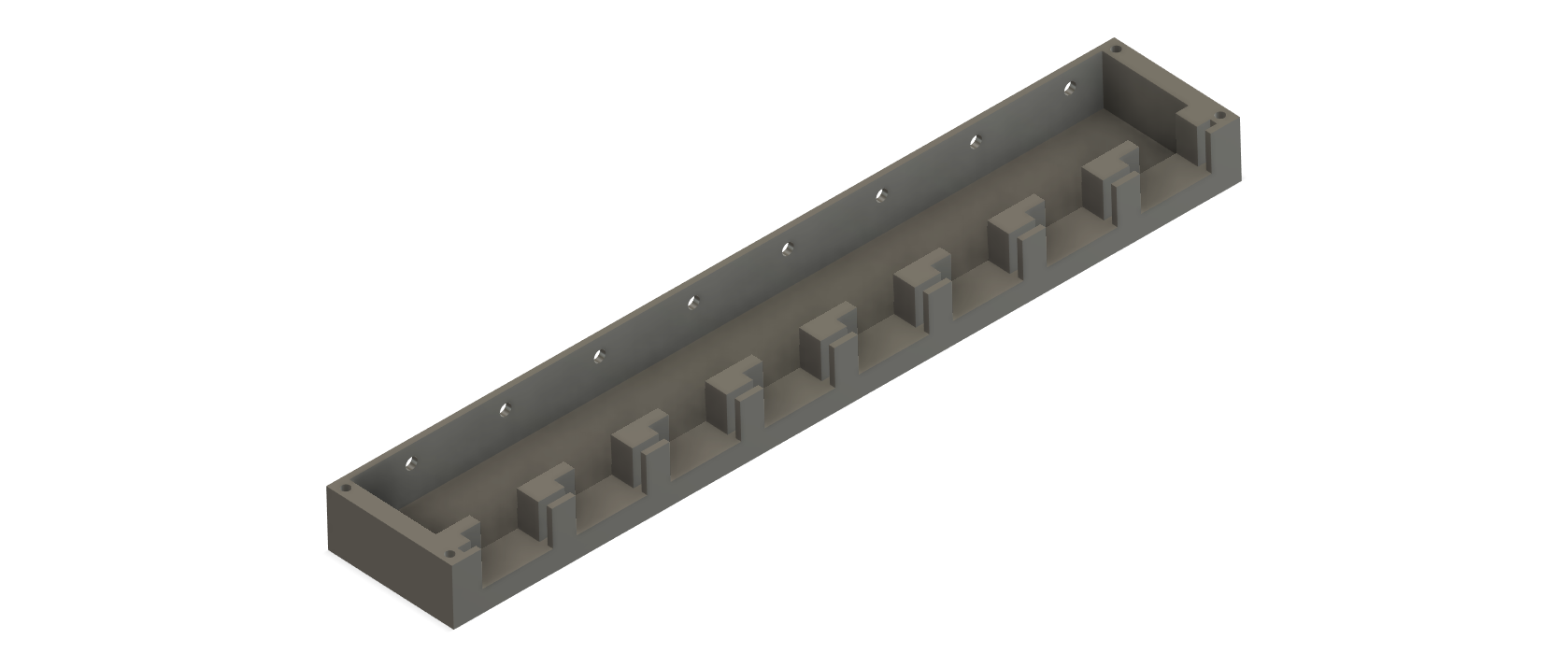
07/19/2020 at 17:02 • 0 commentsThe Flip-Byte
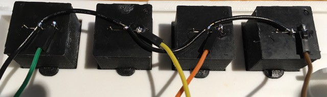
Having sorted out the mechanics with the Flip-Bit it was time to extend that to the 8 bits I will be using for the Tape, a Flip-Byte. So I mashed together 8 of the bases used for the Flip-Bit and came up with this:
![]()
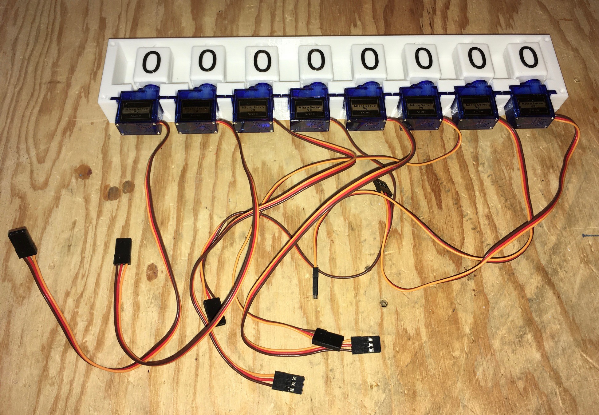
Then following the instructions for constructing the Flip-Bit 8 times I ended up with this:
![]()
Ready to be mounted under the Tape Panel.
-
The Tape Implementation
07/13/2020 at 03:27 • 0 commentsHaving decided that the Tape would be of a fixed size with endmarkers, it was time to consider the underlying implementation. Given the fixed length it seemed simplest to have the Tape be stationary with a movable Head.
Since the endmarkers are immutable, only the inner cells of the tape would ever change between 0 and 1. Such a binary implementation could be accomplished in number of ways including a simple on/off LED. I thought about 7-segment and LCD displays. I started thinking that something more analog would be a good fit for this project and Flip-Dots (Flip-Disks) came to mind. Then it struck me, not Flip-Dot but...
Introducing Flip-Bits
I'll just string eight of these together to form the "input" area of my tape. I'll call that a Flip-Byte ;-)
Making a Flip-Bit
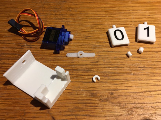
First print the parts. The STL files have been posted to this project.
![]()
You will also require a standard SG90 Micro 9g Servo (from Amazon: SG90 Micro 9g Servo For RC Airplane Car Boat Genuine).
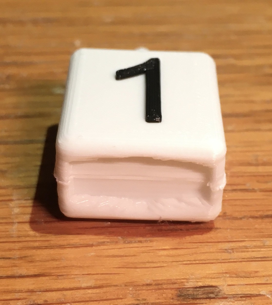
Glue the 1 and 0 pieces together. Use the pegs to help align the two pieces.
![]()
![]()
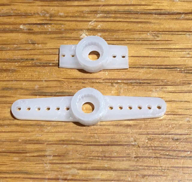
To prepare the servo cut down one of the included horns at the third hole from the center.
![]()
Make sure the servo is in it's 0 position. I hooked mine up to an Arduino and wrote a small program to do this. Attach the horn parallel to the long axis of the servo as shown below.
![]()
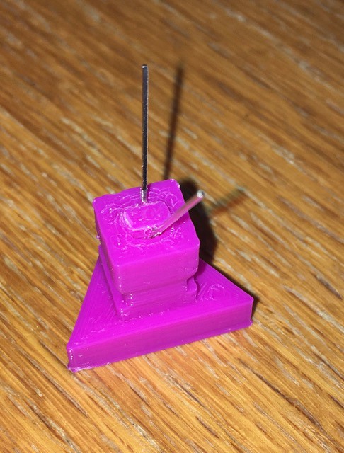
Slide the 0/1 flipper piece loosely into the base.
![]()
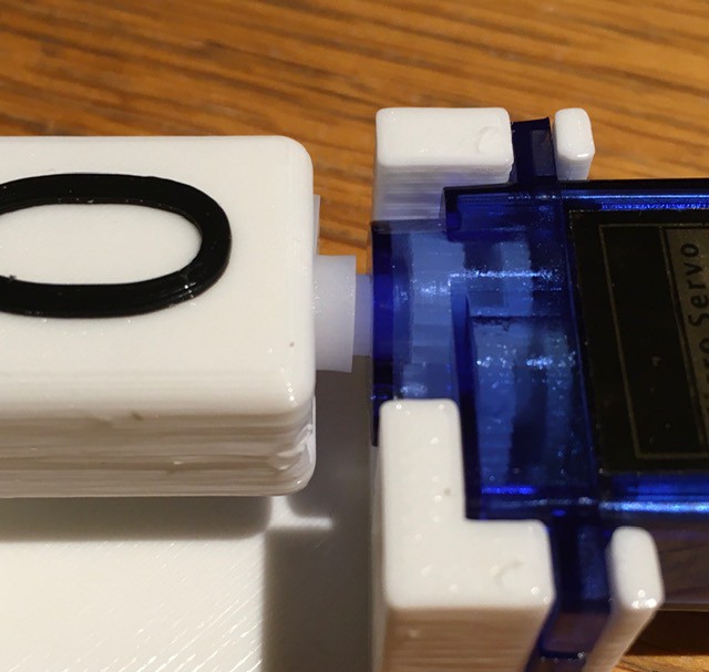
Insert the servo into the base then push the flipper onto the horn.
![]()
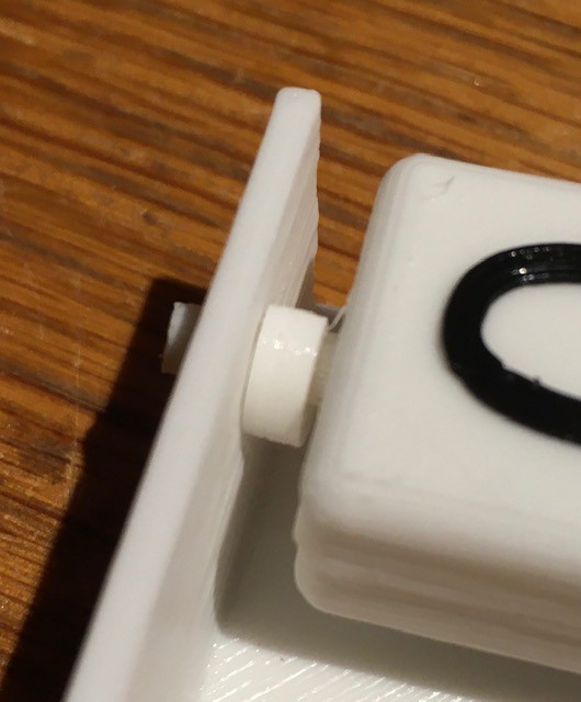
Finally snap the c shaped spacer onto the flipper shaft to hold everything in place.
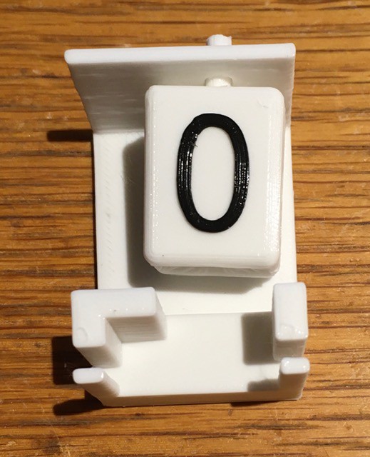
![]()
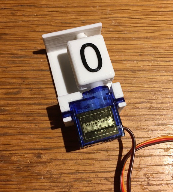
And voila, a Flip-Bit.
![]()
To test the Flip-Bit:
#include <Servo.h>

// Create servo object to control a servo.
Servo myservo;

void setup() {
  // Attaches the servo on pin 9 to the servo object.
  // Adjusts the min and max pulse widths, in microseconds,
  // corresponding to the minimum (0-degree) and maximum
  // (180-degree) angles on the servo.
  myservo.attach(9, 500, 2450);
}

void loop() {
  // Show the zero.
  myservo.write(0);
  delay(500);

  // Show the one.
  myservo.write(180);
  delay(500);
}
I found that I had to tweak the min and max values for the servo attach() method to get the flipper to line up horizontally.
-
About TMD-1
07/13/2020 at 02:01 • 0 commentsOverview
There are numerous variations to the general Turing machine described above. Some have multiple tapes and/or heads. Some tapes are bound (have an end) on the left or right or both. In addition Turing machines have varying numbers of symbols in their alphabets and varying numbers of states. The Turing Machine Demonstrator (TMD-1) will have the following characteristics:
- One tape and one head.
- The alphabet used will have three symbols: {0, 1, b}. 0 will be the blank symbol and b is an endmarker as described below.
- There will be four states: {A, B, C, H}. A will be the start state and H is a special HALT state.
Tale of the Tape
Having a tape that is "arbitrarily extendable" to the left or right would pose some serious implementation issues, not to mention being complete overkill for a 3-symbol / 4-state Turing machine. So I have chosen to implement a restricted form of Turing machine called a "linear bounded automata" (LBA).
In addition to the normal Turing machine behaviors, an LBA has the following three conditions:
- The input alphabet includes two special symbols, serving as left and right endmarkers. In an effort to simplify things even further, TMD-1 will only have a single endmarker symbol (b) in it's input alphabet.
- Transitions may not print other symbols over the endmarkers. In addition, TMD-1 will not allow an endmarker to be written to the other part of the tape.
- Transitions may neither move to the left of the left endmarker nor to the right of the right endmarker. For TMD-1 such a move will HALT the machine.
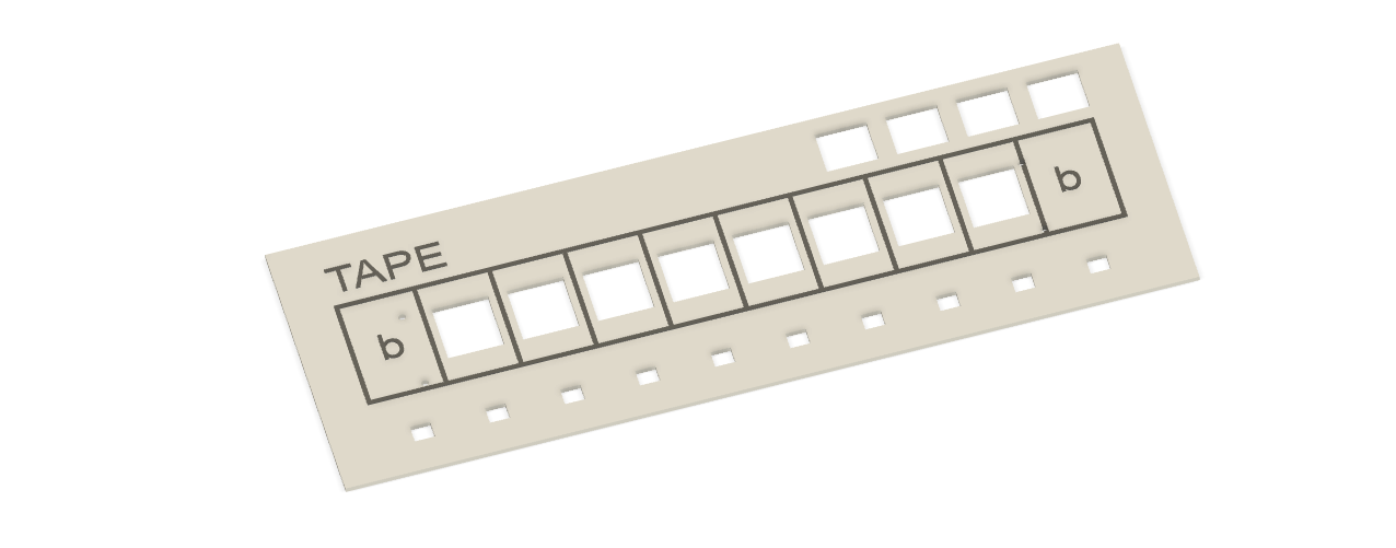
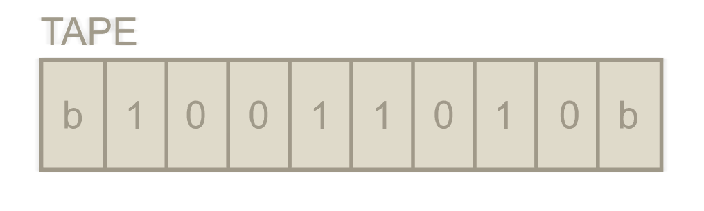
In other words, instead of having potentially infinite tape on which to compute, computation is restricted to the portion of the tape containing the input plus the two tape squares holding the endmarkers. It will look something like this:
![]()
The end cells (endmarkers) cannot be changed and furthermore cannot be written to the other portion of the tape. So the "input" part of the tape will only ever contain zeros and ones.
Finite State Machine
There will be an area on TMD-1 that will allow a user to both define the behavior of the finite state machine (basically the program), as well as see the current state of the machine as it processes each step. I'm very excited about this piece and will reveal more details when I've done a bit more testing.
Controls
In addition there will be controls to:
- Start the machine in either Run or Step mode.
- Enter "data" into the Tape and set the Head's start position prior to running a program.
- Reset the Tape to a known starting state.
The Soul of the Machine
Driving everything will be and Arduino Mega 2560 as I anticipate needing a lot of I/O pins to drive all of the above. The Mega will:
- Implement the finite state machine as defined by the user's input.
- Manage the movement of the Head and the changes to the Tape.
- Process the Controls.
TMD-1: A Turing Machine Demonstrator
Develop a Turing machine that is simple to program and easy to understand.