-
Revision 2.0: CAN, Dual Motors, and Virtual Model Control
02/03/2021 at 04:32 • 0 commentsIn the previous log, I explained how I had got basic closed loop position control working on version 2.0 of the dual motor controller. Profiling showed that this update worked as intended, and the performance is vastly improved. Instead of a 500Hz control loop, this runs its controllers at 4000Hz (including motion primitive planning) for smooth motion control. It was a big jump from a Microchip Cortex M0+ to a STM32 Cortex M4F microcontroller which I was not familiar with. The previous log noted a few next steps, all of which are now complete:
- Set up CAN bus interface (RX and TX)
- Test multiple devices on a network
- Swap out current sense resistors
- Test and tune current control
- Test and tune Virtual Model Controller
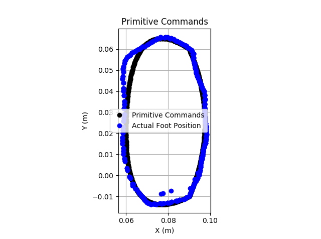
CAN, Dual Motors, and Position PrimitivesI set up the CAN interface, connected two motors, and attached the ESP32-based robot controller via CAN to this device. I then ran a demo running quadratic Bezier curve-based motion primitives. This worked well, as good or better than V1.X. In this case, the performance seems to be mostly limited by the motor, but the control sounds noticeably smoother. The tracking performance is quite good. The image below is tracking the path with a 1500ms period.
![]()
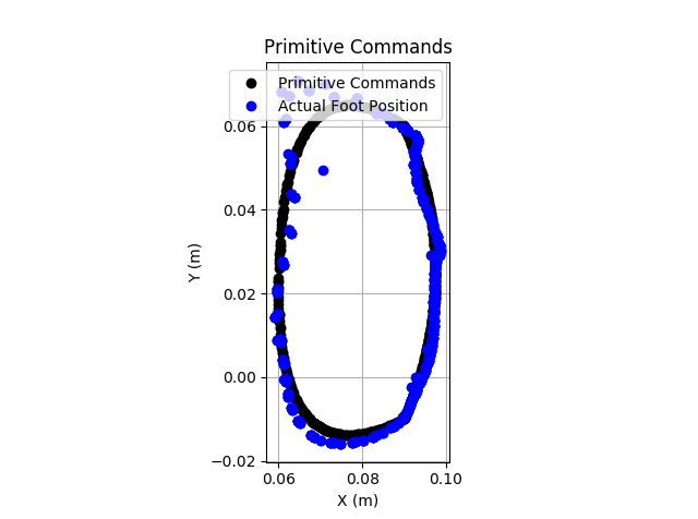
Even moving faster, the tracking performance is quite good. The image below is operating with a 750ms period. There is some limited performance as the foot moves rapidly from positive Y back, but this appears to be a motor limitation more than a controller issue (as indicated by motor saturation.)
![]()
Current ControlVersion 1.X of this project had significant computational limitations which did not allow me to run current control fast enough to get good virtual model control results. With 8X control loop rate improvement, this version promises improvements in current control. Interestingly, the control loops is now fast enough (4kHz) that it is approaching the frequency of the motor driving PWM (currently 8.4kHz). Therefore, each control cycle sets effectively 2 pulses of the PWM on each loop!
The original current sense resistors were set to 0.24 Ohm, which did not provide enough resolution. I have a 3.0V reference and a 12-bit ADC, so it was not measuring the small currents of these motors very well. I replaced that with 2.14 Ohm resistors, and have much improved resolution. Ideally, this will be improved in the future with a smaller resistor and a current sense amplifier, but it seems to work for now.
The current on each motor is sampled at 20kHz and digitally low-pass filtered. The low-pass filter was designed with a 90% rise time of ~11ms. This current feedback signal seems quite reliable so far.
A PI controller is used for the current control. This controller is tuned to be almost entirely an integral controller, so that the command is ramped up and down and doesn't make major jumps. This seems to work quite well.
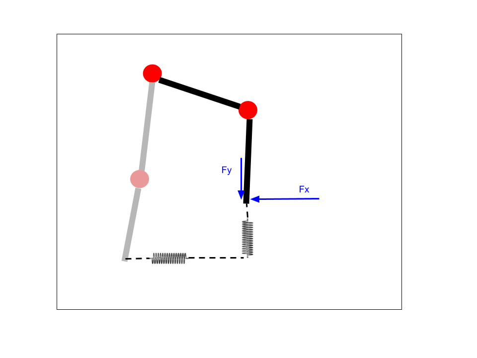
Virtual Model ControlWith effective current control, virtual model control can now reliably be performed. As implemented, a virtual spring and damper in both X and Y directions in the cartesian space are connected between the current foot position and some desired position determined based on a motion primitive. The motor torques are determined (assuming no friction and no gravity, which I may account for in the future) using the transpose of the Jacobian. Then, assuming a linear relationship between motor torque and motor current, the torque is applied via current control. The image below shows the basic concept.
![]()
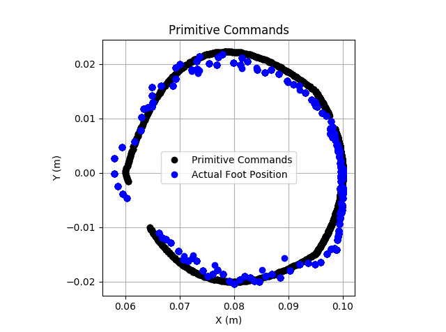
While this control approach makes a number of assumptions that may be much less reasonable on these cheap, high ratio gearmotors than high-end motors used in academic or commercial robotics, it does appear to work reasonably well. The image below shows tracking through a quadratic Bezier curve based motion primitive using this virtual model control with a 3000ms period.
![]()
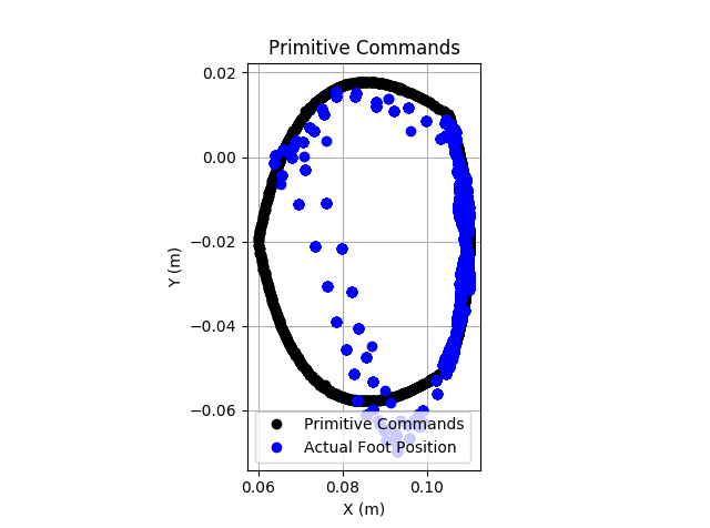
The VMC does struggle with fast movements. While the above motion primitive had roughly constant foot speed throughout the motion, the primitive below moves rapidly "up, back, and down" to return the foot to the start of a walking cycle. By increasing the virtual stiffness or using some look-ahead feedforward term I may be able to improve this performance.
![]()
SummaryI am very happy with the results of this new revision so well. With vastly superior performance, it enables more advanced control techniques to be used without worry. There are a few minor additions to the firmware still needed to match the capability set of V1.X, after which I plan to replace the controllers on my quadruped robot with V2.0 and test walking under virtual model control. That will be the closest mimic to advanced robots like the MIT Cheetah that this project has yet achieved.
I also plan to open up the GitHub repo soon, with all code released under MIT license.
-
Revision 2.0 Initial Testing
01/13/2021 at 03:15 • 0 commentsAs discussed in the previous log, I developed a 2.0 version with a main goal of improved performance. I upgraded the microcontroller from a Cortex-M0 core to a Cortex-M4F alternative. While doing this, I also jumped from Microchip's SAM line of microcontrollers to the STM32 family. I am relatively new to STM32, but this project is a good learning experience.
The STM32CubeIDE makes it easy to set up all the peripherals and middleware such as FreeRTOS. Because the previous version was built on FreeRTOS, and most of the more complicated code was agnostic to hardware, porting the firmware over was fairly straightforward. So far, I have:
- System boots up and FreeRTOS is running
- Position control and motion primitives are working
![]()
![]()
Control OptimizationIn previous analysis, the calculations for motion primitives to determine the next setpoint were separate from the low-level control loop calculations. This was done due to limitations with how slow the primitives calculations were. Originally, before optimizations the motion primitive calculation took 1.88ms and the control loop took 236us. By setting up pre-calculations and implementing the control loop with only integer math used, this was much improved. However, the pre-calculations were very memory limited, and it was still not very fast. This new microcontroller is much faster.
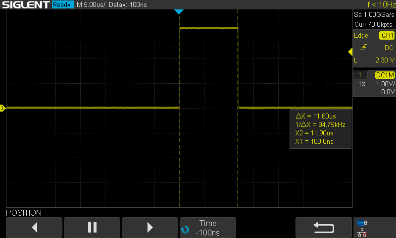
Now, with a floating point PID controller used for motor control, the control loop itself only takes about 11.8us!
![]()
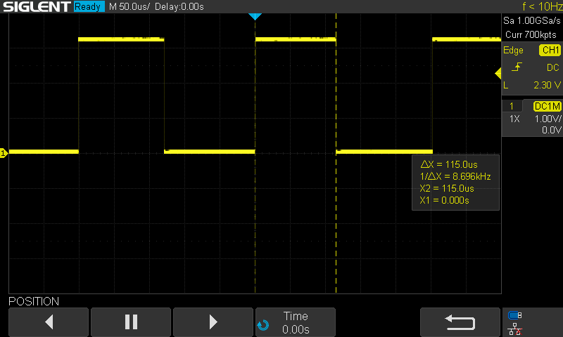
That is great, meaning we can set the controller to run much faster, get better current control, and smoother motion. I therefore updated the control rate to 4kHz (from 500Hz originally). I also set the controller to motion primitive mode, which calculates a Bezier curve, inverse kinematics of the leg, and PID control of both motors on each cycle. Without optimization, this requires 115us. This is about 18X faster than the previous version! We can also see here that the loop is running at 4kHz now.
![]()
![]()
While this is probably good enough, I wanted to do a bit more optimization. The inverse kinematics use both arccos and arctan functions. I figure that these are likely slow, so set about to make faster lookup table versions. This is still a work in progress to improve its accuracy, but did speed up the calculations down to 75us total, now 28X faster than V1.0. While not measured, I couldn't tell the difference visually or audibly using the fast versions versus direct calculation.
![]()
Next Steps- Set up CAN bus interface (RX and TX)
- Test multiple devices on a network
- Swap out current sense resistors
- My chosen values were too low, I forgot that the SAMD21 ADC has a PGA but the STM32 does not
- Test and tune current control
- Test and tune Virtual Model Controller
-
Revision 2.0: Microcontroller upgrade
12/19/2020 at 19:39 • 0 commentsI have been using this motor controller for building a small walking robot. During further development of that project, specifically trying to get virtual model control working correctly, I started running into performance issues. Even with performance optimizations, there was only so much I could do without really significant effort. I have been using the SAMD21 microcontroller, a Cortex M0 core running at 48MHz and 32KB of SRAM. It does not have an FPU, which was starting to be a major issue. When I tried to perform significant pre-calculations of the motion profiles, I ran into memory issues. The clear next revision then was to move up to a more powerful microcontroller, particularly one with an FPU. My projects are also as much about learning as building stuff, so I also decided to use an STM32 since I have limited experience with those. I have also been building more PCBs with JLCPCB, and they have numerous STM32 options.
I chose the STM32F407, which represents a really significant upgrade in many ways:
- Clock rate increase to 168MHz (3.5X faster)
- Memory increase to 192KB (6X more)
- Has an FPU (likely 50+X faster for some operations, not including clock speed upgrades)
- Has an onboard CAN controller
- Has multiple onboard quadrature decoders (reduce overhead from interrupts used on SAMD21 version)
Besides the major upgrade on the MCU, I made a few other usability upgrades:
- Added 2 LEDs for status indication
- Voltage reference for more accurate current feedback
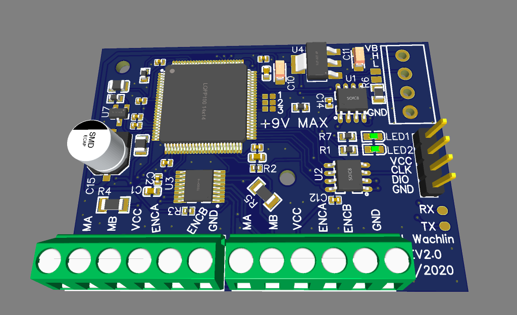
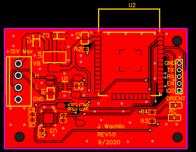
The image below shows the upgraded design. The connectors and mounting holes have not moved, so that I can easily swap out the older versions. This design has been ordered and I'm just waiting for it to arrive. In the meantime I can make some progress on the firmware, pulling in much of the development work I made for the SAMD21 into the STM firmware.
![]()
-
Quadruped Walking and Gait Testing
10/19/2020 at 21:58 • 0 commentsThe last log covered some of the preparation for building a walking quadruped robot using four of the dual motor controllers, one for each leg. The parts for doing this have now arrived, and I have been working on getting the system walking.
Leg Trajectory Simulation
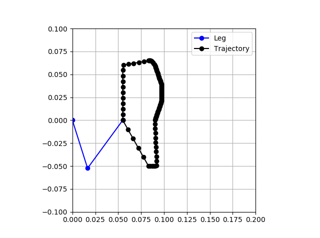
While I had previously shown the motor controller controlling a leg through a motion profile, this profile was a complete guess and not based on any research. Unsurprisingly, that motion profile did not work well to get the system moving. I therefore decided to write a Python kinematic simulator that could be used to rapidly evaluate motion profiles, see if they are in the leg's reachable area, and ensure my inverse and forward kinematics are correct. I set it up roughly as a mirror of the C code running on the leg controller to ensure that process is correct. I give it a set of keyframes. Each keyframe consists of an x and y cartesian space coordinate and a value that indicates at what part of the cycle period it should reach that point. All other desired positions are linearly interpolated between those points. These desired positions are fed first into the inverse kinematic solver to calculate joint angles, then the forward kinematic solver to calculate knee and foot positions. This step will fail if the desired position is outside of the reachable area. The positive X axis is "down" and the positive Y axis is "forward," with the origin at the hip. The blue line in the image below shows the leg, with circle markers at the hip, knee, and foot. The black dots are the foot positions throughout the trajectory, equally spaced in time. Therefore, they are more bunched together during slower motions and more spaced apart during fast movements.
![]()
Clearly, this is an odd and complication motion and it is unsurprising that it doesn't work well.
Gaits
With my motion profile guess not working well, I spent some time reviewing research into quadrupedal robots. One of the most well known is the MIT Cheetah. I had the pleasure of taking Professor Sangbae Kim's Bioinspired Robotics course at MIT, and it was a fascinating introduction to the topic in general and to the MIT Cheetah in particular. Researchers have long classified different gaits for walking animals, including the trot, gallop, pronk, and bound. The following video in particular shows these various actions on the MIT Cheetah. Even if you don't know these gait classification terms, you will recognize the motions.
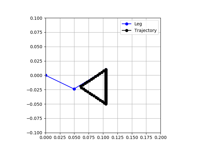
These motions serve as a starting inspiration for the gaits I will implement on my robot. I started with the slow trot, shown at about 0:25 into that video. From the video, we can gain some insight into how this gait is implemented. The front right leg and rear left leg are in sync, and the front left leg is in sync with the rear right leg. Throughout the motion, the foot is on the ground roughly 3X longer than it is in the air. The trajectory is shifted rearwards of the hip, so that the front of the trajectory is just slightly forward of the hip. Although the trajectory is likely more complex, and is skewed due to the proprioceptive control used, it looks to my eye roughly to be a triangle with side lengths that are roughly equal. The image below shows the trajectory generated for this gait. It matches all these observed characteristics.
![]()
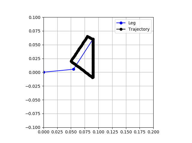
The next gait is called the fast trot at about 0:32 in that video. Again, this is not very precise, but we can extract some rough characteristics from what we see. As with the slow trot, the front right leg and rear left leg are in sync and the front left leg is in sync with the rear right leg. However, here the foot is on the ground roughly the same amount of time that it is in the air. Because of this, most of the time only two feet are touching the ground. In the slow trot, there is a lot of time with all four feet contacting. This motion profile is shifted more forward, with the rear just back of the hip. It looks roughly triangular, but shorter and longer. However, on ground contact, the foot does appear to be moving backwards already. The image below shows this proposed trajectory.
![]()
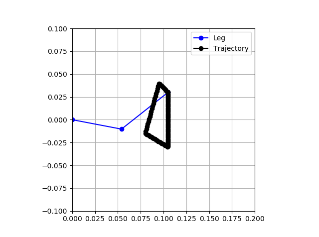
The bound gait looks more like a gait a rabbit or frog would use than one a dog would. However, the gait of a running cheetah or dog actually looks somewhat bound-like. In the example in the video at around 0:40, the front legs move together and the rear legs move together. Each foot is on the ground roughly the same amount of time that it is in the air. The motion is roughly centered about the hip. It follows sort of a sharp triangle motion. The image below shows the proposed profile.
![]()
The video also shows a gallop and pronk, but we are not yet ready to try that, and I'm not sure the hardware could do it yet.
DISCLAIMER
Note that the MIT Cheetah does not actually use these profiles. They are simplified versions extracted by eye from videos. In fact, they use more complicated profiles. One of their academic papers shows the leg profiles as mostly rounded-rectangle-looking Bezier curves, and show that the back legs were given different profiles from the front legs. In addition, due to the proprioceptive control used, the "positional tracking" is actually quite poor, but poor on purpose.
Implementation
Since the Python code was set up to be very similar to the C implementation, bringing in the proposed motion profiles was simple. I now have 4 different motion primitives corresponding to these 4 gaits.
void motion_primitive_init(void)
 {
    // Leg straight, motors at zero is leg straight down +x. Forward is +y
    /*
    *                O-> +y
    *                | \
    *            +x \/   \
    *                     O
    *                     |
    *                     |
    *                     O
    *
    */

    // t_part must be always increasing, never > 1.0. Must be a cyclical motion primitive

    // Slow trot walk
    // Triangular, roughly 3X longer on ground than in air, front slightly forward of hip
    primitives[0].num_keyframes = 3;
    primitives[0].tau = 2.0;
    primitives[0].t_offset = 0.0;
    primitives[0].invert = 0;
    primitives[0].time_reverse = 0;
    primitives[0].x_offset_m = 0;
    primitives[0].y_offset_m = 0;
    primitives[0].x_scale = 1.0;
    primitives[0].y_scale = 1.0;

    primitives[0].frames[0].t_part = 0.0;
    primitives[0].frames[0].x = 0.105;
    primitives[0].frames[0].y = 0.01;

    primitives[0].frames[1].t_part = 0.75;
    primitives[0].frames[1].x = 0.105;
    primitives[0].frames[1].y = -0.05;

    primitives[0].frames[2].t_part = 0.875;
    primitives[0].frames[2].x = 0.06;
    primitives[0].frames[2].y = -0.02;

    // Fast trot walk
    // Mostly triangular, in air roughly same as on ground, rear slightly backward of hip
    primitives[1].num_keyframes = 4;
    primitives[1].tau = 2.0;
    primitives[1].t_offset = 0.0;
    primitives[1].invert = 0;
    primitives[1].time_reverse = 0;
    primitives[1].x_offset_m = 0;
    primitives[1].y_offset_m = 0;
    primitives[1].x_scale = 1.0;
    primitives[1].y_scale = 1.0;

    primitives[1].frames[0].t_part = 0.0;
    primitives[1].frames[0].x = 0.09;
    primitives[1].frames[0].y = 0.06;

    primitives[1].frames[1].t_part = 0.5;
    primitives[1].frames[1].x = 0.09;
    primitives[1].frames[1].y = -0.01;

    primitives[1].frames[2].t_part = 0.75;
    primitives[1].frames[2].x = 0.05;
    primitives[1].frames[2].y = 0.02;

    primitives[1].frames[3].t_part = 0.95;
    primitives[1].frames[3].x = 0.08;
    primitives[1].frames[3].y = 0.065;

    // Bound
    // Mostly triangular, in air roughly same as on ground, centered on hip
    primitives[2].num_keyframes = 4;
    primitives[2].tau = 2.0;
    primitives[2].t_offset = 0.0;
    primitives[2].invert = 0;
    primitives[2].time_reverse = 0;
    primitives[2].x_offset_m = 0;
    primitives[2].y_offset_m = 0;
    primitives[2].x_scale = 1.0;
    primitives[2].y_scale = 1.0;

    primitives[2].frames[0].t_part = 0.0;
    primitives[2].frames[0].x = 0.105;
    primitives[2].frames[0].y = 0.03;

    primitives[2].frames[1].t_part = 0.5;
    primitives[2].frames[1].x = 0.105;
    primitives[2].frames[1].y = -0.03;

    primitives[2].frames[2].t_part = 0.7;
    primitives[2].frames[2].x = 0.08;
    primitives[2].frames[2].y = -0.015;

    primitives[2].frames[3].t_part = 0.9;
    primitives[2].frames[3].x = 0.095;
    primitives[2].frames[3].y = 0.04;

    // Pronk
    // Only vertical motion, slow down, fast down, fast up, fast to nominal
    primitives[3].num_keyframes = 5;
    primitives[3].tau = 2.0;
    primitives[3].t_offset = 0.0;
    primitives[3].invert = 0;
    primitives[3].time_reverse = 0;
    primitives[3].x_offset_m = 0;
    primitives[3].y_offset_m = 0;
    primitives[3].x_scale = 1.0;
    primitives[3].y_scale = 1.0;

    primitives[3].frames[0].t_part = 0.0;
    primitives[3].frames[0].x = 0.07;
    primitives[3].frames[0].y = 0.0;

    primitives[3].frames[1].t_part = 0.3;
    primitives[3].frames[1].x = 0.09;
    primitives[3].frames[1].y = 0.0;

    primitives[3].frames[2].t_part = 0.4;
    primitives[3].frames[2].x = 0.105;
    primitives[3].frames[2].y = 0.0;

    primitives[3].frames[3].t_part = 0.5;
    primitives[3].frames[3].x = 0.05;
    primitives[3].frames[3].y = 0.0;

    primitives[3].frames[4].t_part = 0.6;
    primitives[3].frames[4].x = 0.07;
    primitives[3].frames[4].y = 0.0;
 }
I then set up the main ESP32 robot controller to cycle through these gaits, using the appropriate leg pairings when it did. I noticed during the fast trot that the system was tilted back significantly (likely due to PID tuning), so as a quick fix I added some primitive offsets on those commands. Also the random short delays are because I am having some bug with CAN right now reducing reception rates.
#include <CAN.h>
#include "dual_motor_can.h"

#define CAN_RX_PIN      4
#define CAN_TX_PIN      5
#define LED2_PIN              16

#define FRONT_LEFT            (1)
#define FRONT_RIGHT           (2)
#define REAR_RIGHT            (3)
#define REAR_LEFT             (4)

#define MOTOR_0                (0)
#define MOTOR_1                (1)

#define PRIMITIVE_SLOW_TROT    (0)
#define PRIMITIVE_FAST_TROT    (1)
#define PRIMITIVE_BOUND        (2)
#define PRIMITIVE_PRONK        (3)

#define INVERT                (1)
#define NO_INVERT             (0)

#define REVERSE               (1)
#define NO_REVERSE            (0)

#define NUM_PRIMITIVES        (4)
#define PRIMITIVE_CHANGE_PERIOD_MS  (10000)

static uint8_t prim_index = 0;
static uint8_t primitives[NUM_PRIMITIVES] = {PRIMITIVE_SLOW_TROT, PRIMITIVE_FAST_TROT, PRIMITIVE_BOUND, PRIMITIVE_PRONK};

void set_legs_mode(uint8_t prim)
{
  if(prim == PRIMITIVE_SLOW_TROT)
  {
    send_primitive_command(FRONT_LEFT, prim, NO_INVERT, NO_REVERSE, 1000, 0);
    delay(50);
    send_primitive_command(FRONT_RIGHT, prim, INVERT, NO_REVERSE, 1000, 500);
    delay(50);
    send_primitive_command(REAR_RIGHT, prim, INVERT, NO_REVERSE, 1000, 0);
    delay(50);
    send_primitive_command(REAR_LEFT, prim, NO_INVERT, NO_REVERSE, 1000, 500);
    delay(50);
  }
  else if(prim == PRIMITIVE_FAST_TROT)
  {
    send_primitive_params(FRONT_LEFT, prim, -5, 0, 100, 100); // Shift front upwards
    delay(50);
    send_primitive_command(FRONT_LEFT, prim, NO_INVERT, NO_REVERSE, 1000, 0);
    delay(50);
    send_primitive_params(FRONT_RIGHT, prim, -5, 0, 100, 100); // Shift front upwards
    delay(50);
    send_primitive_command(FRONT_RIGHT, prim, INVERT, NO_REVERSE, 1000, 500);
    delay(50);
    send_primitive_params(REAR_RIGHT, prim, 5, 0, 100, 100); // Shift rear downwards
    delay(50);
    send_primitive_command(REAR_RIGHT, prim, INVERT, NO_REVERSE, 1000, 0);
    delay(50);
    send_primitive_params(REAR_LEFT, prim, 5, 0, 100, 100); // Shift rear downwards
    delay(50);
    send_primitive_command(REAR_LEFT, prim, NO_INVERT, NO_REVERSE, 1000, 500);
    delay(50);
  }
  else if(prim == PRIMITIVE_BOUND)
  {
    send_primitive_command(FRONT_LEFT, prim, NO_INVERT, NO_REVERSE, 1000, 0);
    delay(50);
    send_primitive_command(FRONT_RIGHT, prim, INVERT, NO_REVERSE, 1000, 0);
    delay(50);
    send_primitive_command(REAR_RIGHT, prim, INVERT, NO_REVERSE, 1000, 500);
    delay(50);
    send_primitive_command(REAR_LEFT, prim, NO_INVERT, NO_REVERSE, 1000, 500);
    delay(50);
  }
  else if(prim == PRIMITIVE_PRONK)
  {
    send_primitive_command(FRONT_LEFT, prim, NO_INVERT, NO_REVERSE, 1000, 0);
    delay(50);
    send_primitive_command(FRONT_RIGHT, prim, INVERT, NO_REVERSE, 1000, 0);
    delay(50);
    send_primitive_command(REAR_RIGHT, prim, INVERT, NO_REVERSE, 1000, 0);
    delay(50);
    send_primitive_command(REAR_LEFT, prim, NO_INVERT, NO_REVERSE, 1000, 0);
    delay(50);
  }
}

void setup() {
  Serial.begin(115200);

  pinMode(LED2_PIN, OUTPUT);
  digitalWrite(LED2_PIN, LOW);

  Serial.println("CAN position control demo");

  CAN.setPins(CAN_RX_PIN, CAN_TX_PIN);

  // start the CAN bus at 1000 kbps
  if (!CAN.begin(1000E3)) {
    Serial.println("Starting CAN failed!");
    while (1);
  }

  delay(4003);

  // sync at start
  for (int i = 1; i <= 4; i++)
  {
    delay(30);
    send_time_sync(i, millis());
  }

  // Track profiles
  set_legs_mode(PRIMITIVE_SLOW_TROT);

  digitalWrite(LED2_PIN, HIGH);
}

void loop() {
  static uint32_t last_mode_change = 0;
  delay(1000);
  digitalWrite(LED2_PIN, !digitalRead(LED2_PIN));
  // Keep synced
  for (int i = 1; i <= 4; i++)
  {
    delay(30);
    send_time_sync(i, millis());
  }

  if(millis() - last_mode_change > PRIMITIVE_CHANGE_PERIOD_MS)
  {
    last_mode_change = millis();
    prim_index++;
    if(prim_index >= NUM_PRIMITIVES)
    {
      prim_index = 0;
    }
    set_legs_mode(primitives[prim_index]);
  }
}
WALKING ROBOTS!!
Now the part you actually care about, videos of the gaits. First, the slow trot. Due to the high CG and no stability controller, this motion is somewhat unstable, but it does work!
Next, the fast trot. While this does work, it doesn't look quite like the MIT Cheetah's gait. The whole system leans back, and the rear legs drag as they come forward. This gait can use some improvement but it moves in the right direction.
Finally, the bounding gait. This works marginally. If the timing is right, the system does bound properly. If not, it doesn't really move. It's also worth noting it moves in the opposite direction of what was intended, so not sure I can call that a success just yet.
SummaryI now have a working quadruped robot that I can develop gaits, higher level stability controllers, and more!
-
CAN ICD, Quadruped Prep, and Motion Playback
10/04/2020 at 21:59 • 0 commentsCAN ICD
This log is a mixed bag of a variety of related efforts. The first task was to generate a proper CAN interface control document (ICD). I had previously been adding new CAN messages simply by manually synchronizing the Arduino code for the ESP32 controller and the Atmel Studio project for the SAMD21 on the motor controller. Instead, these should both reference back to a ground-truth ICD. This document is a work in progress and will continue to be modified, but revision 1.0 is on the project page.
Quadruped PrepWhile I intend to eventually build a bipedal robot, I want to start with a simpler version first. I plan to build a small quadruped robot that I want to be able to, at minimum:
- Walk forward
- Walk backwards
- Turn in place
I also want to dig into some more complicated and difficult tasks:
- Walking on non-level or cluttered surfaces
- Detect foot contact with current increase?
- Ambulate with various gaits
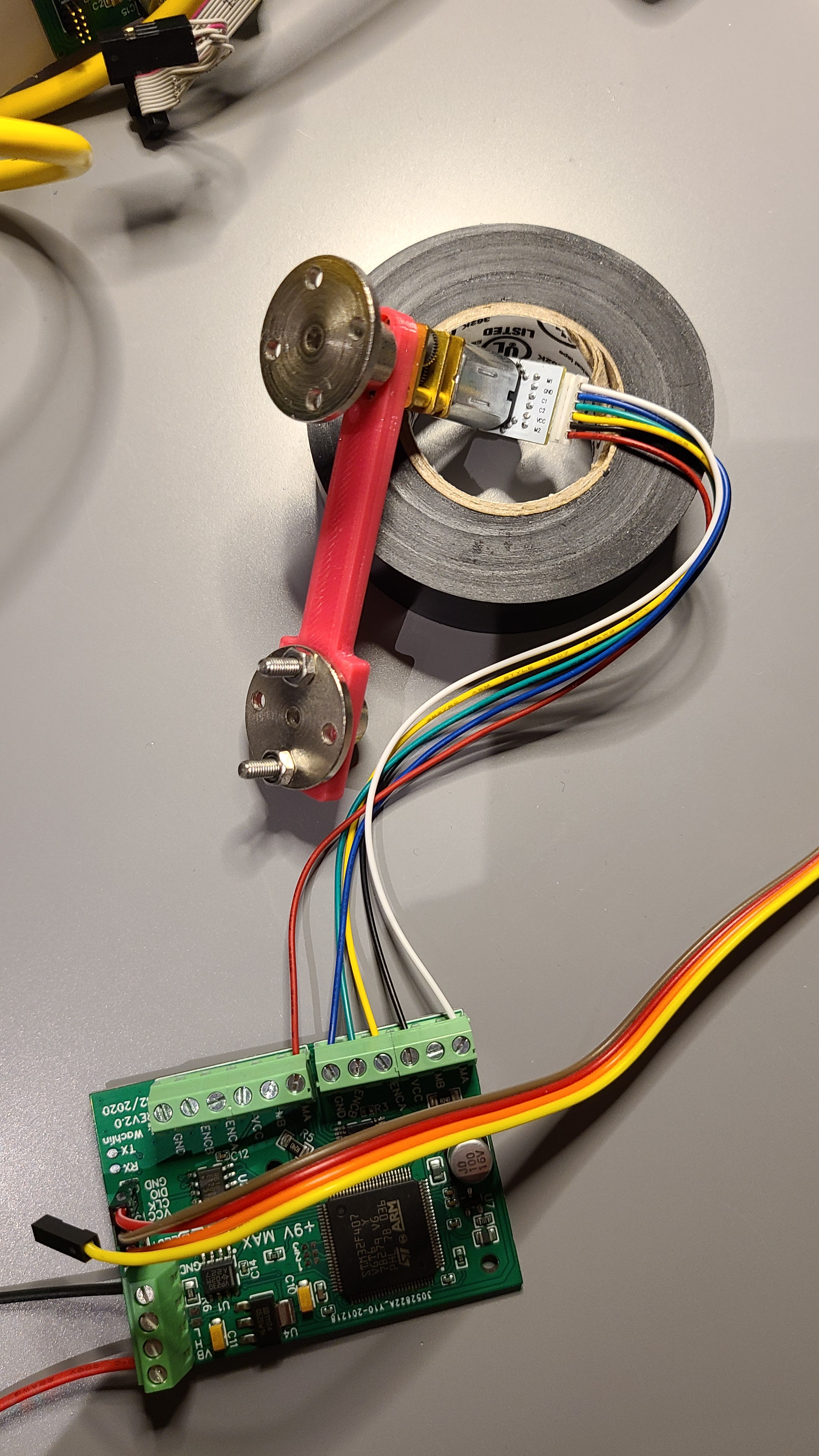
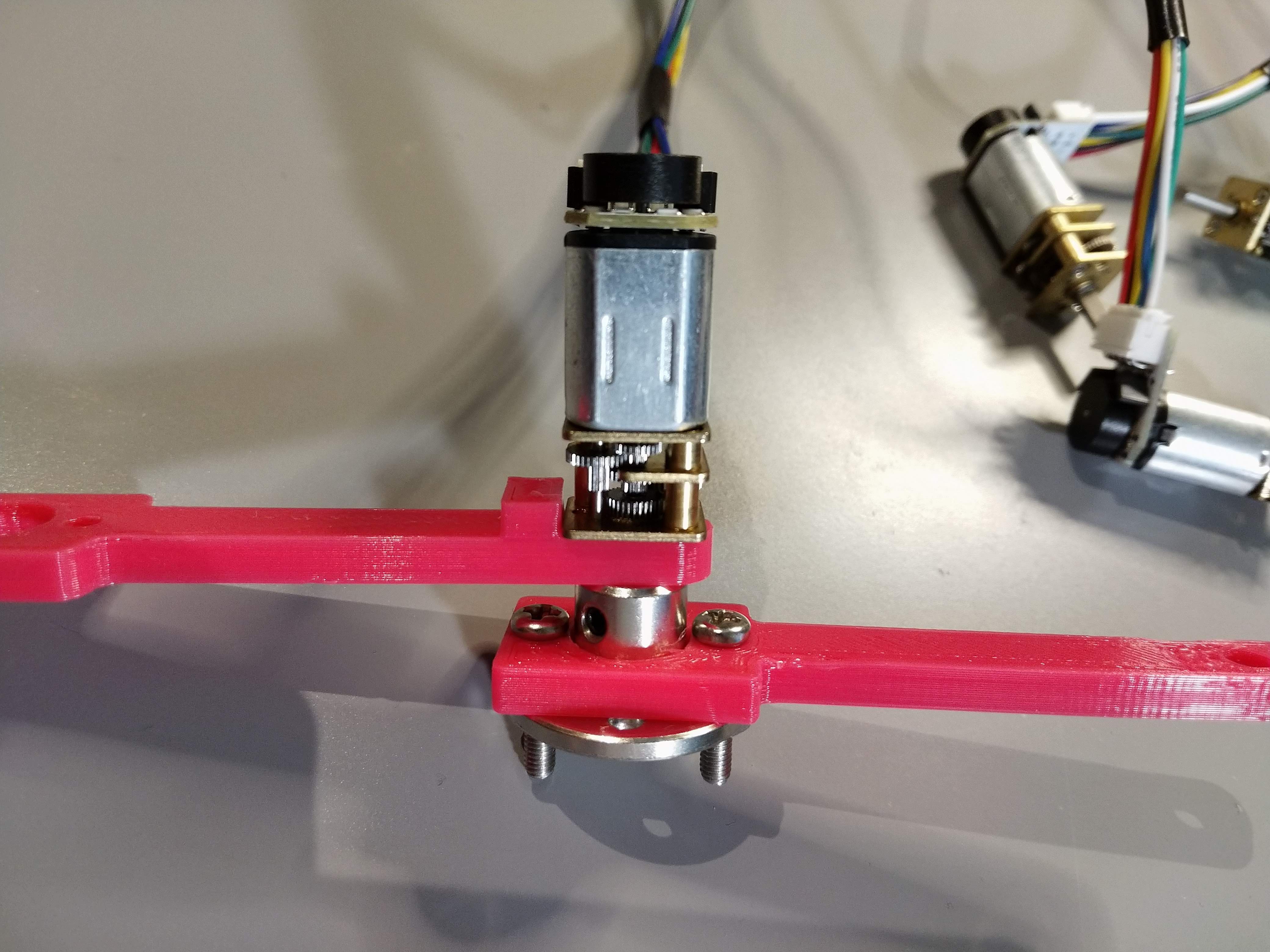
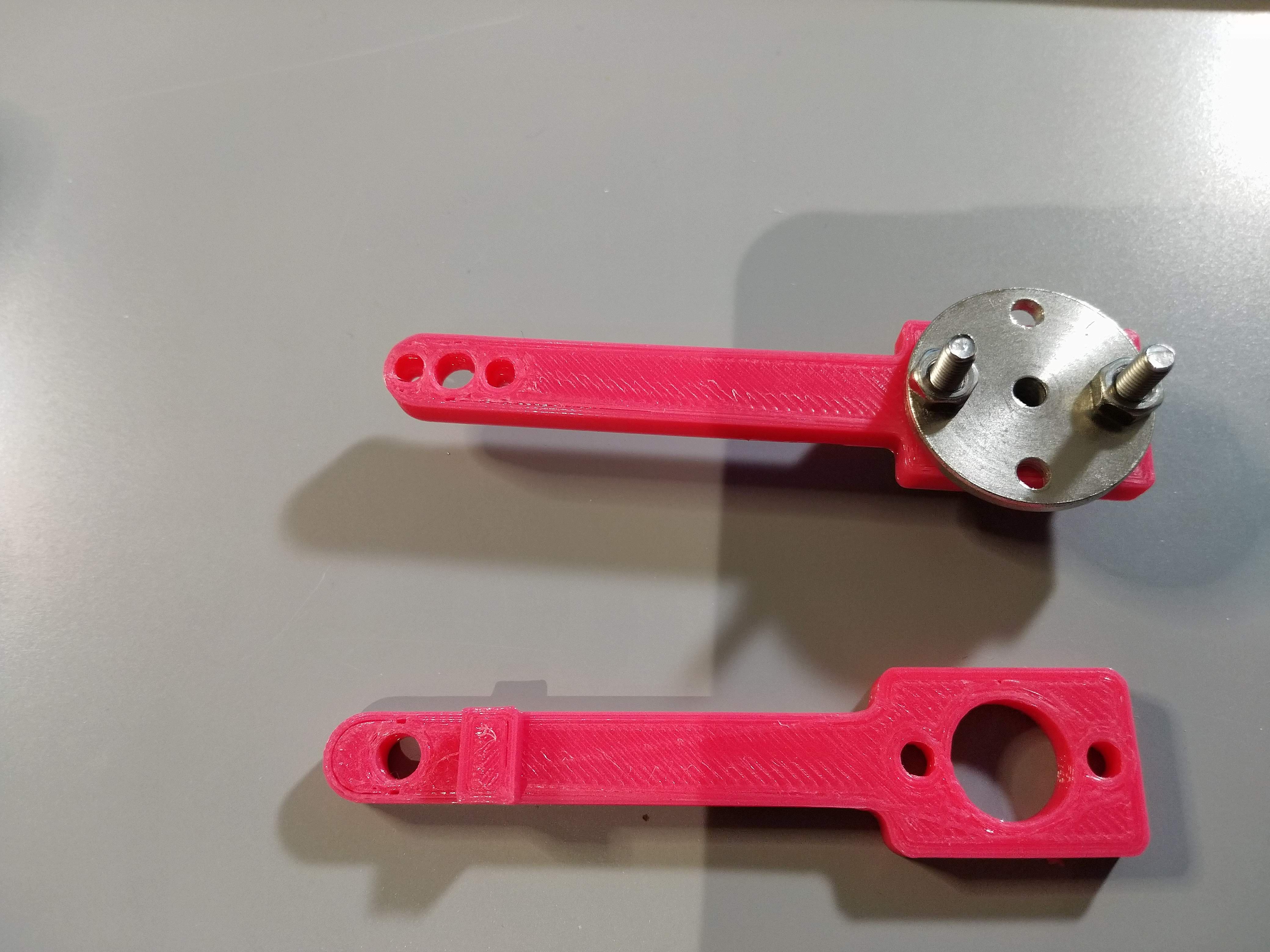
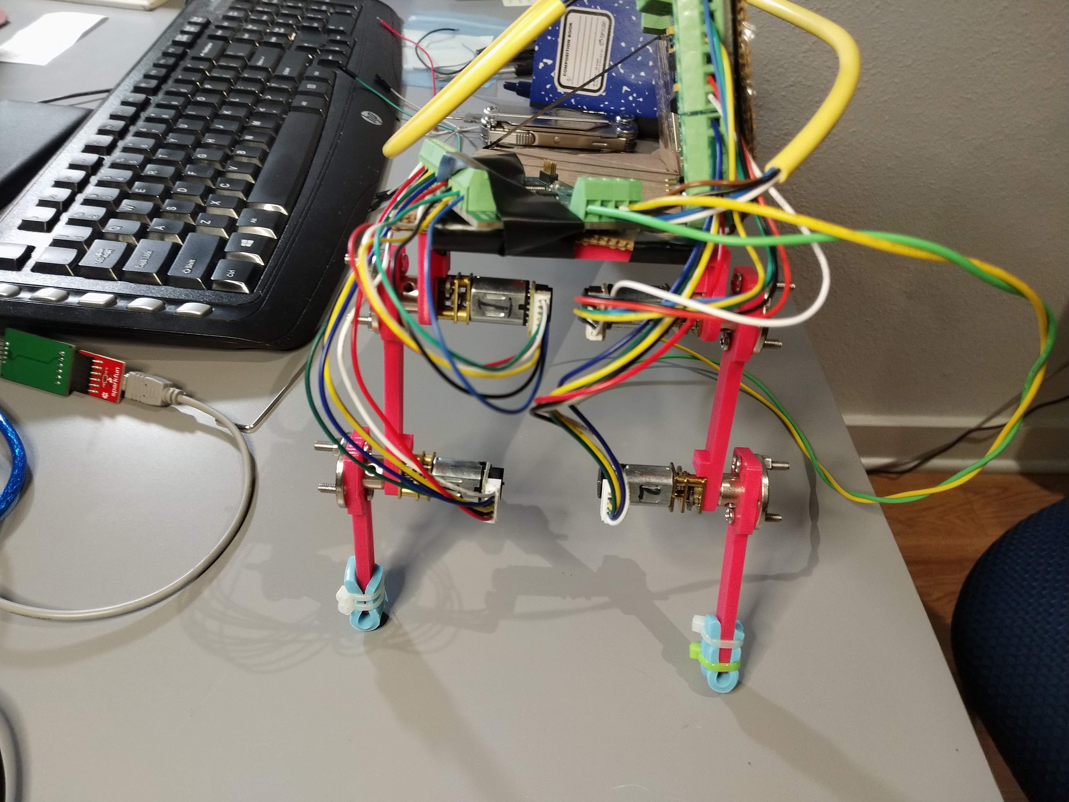
In preparation for this, I needed something far less janky than my cardboard structure previously shown. I had a square of HDPE that I will use as the backbone, and will use 3D printed legs. The previous 3D printed legs I had used had a large amount of backlash built in. This was because the motors were not actually bolted to any frame. Instead, a structure was printed to jam the motor in place, and the set screws on the hubs held the assembly together. The image below shows this at the knee joint.
![]()
Clearly, that is not a great long-term solution. The motors' front plates have two M1.6 mounting screws. I purchased some of those, and printed new parts with counterbored holes for those screws. I am still waiting on the screws to arrive, but the following image compares the two "femur" designs. Obviously these are not great feats of mechanical engineering, but to start out I think they should work OK.
![]()
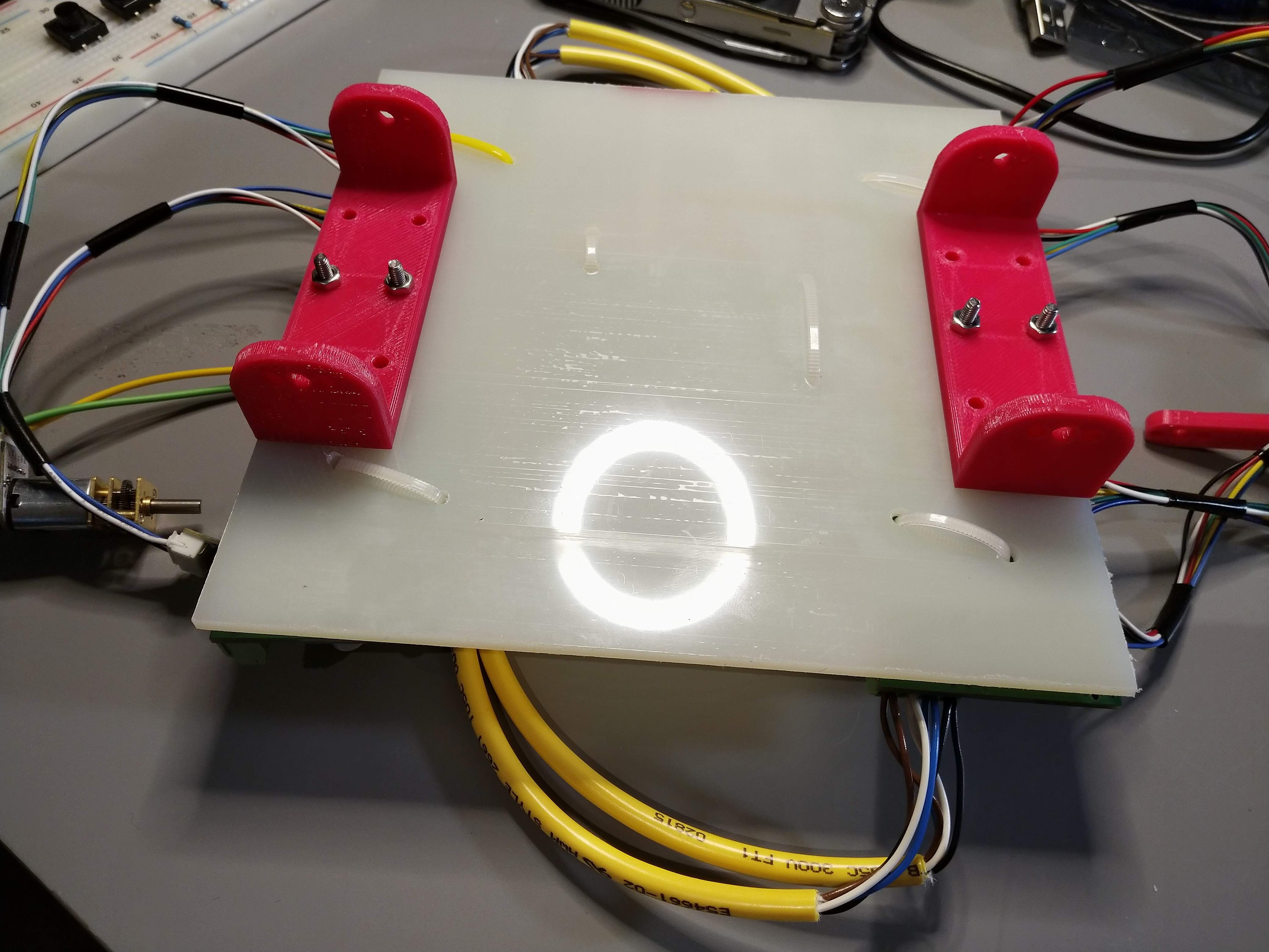
The legs will attach to 3D printed mounts bolted to the HDPE sheet backbone. The image below shows the underside of this with the mounts attached. The mounts all have the appropriate counterbored holes for the motor mounting screws.
![]()
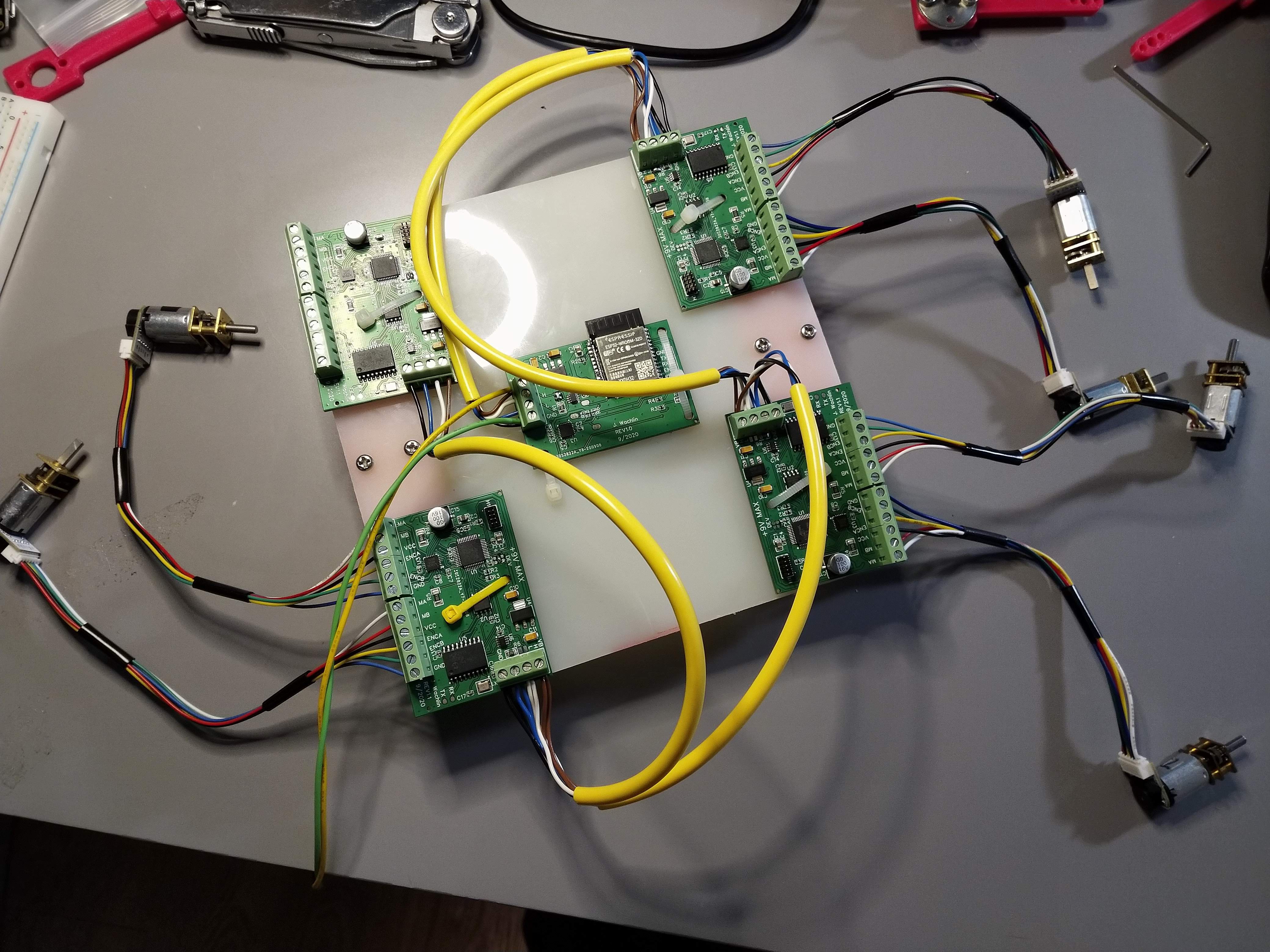
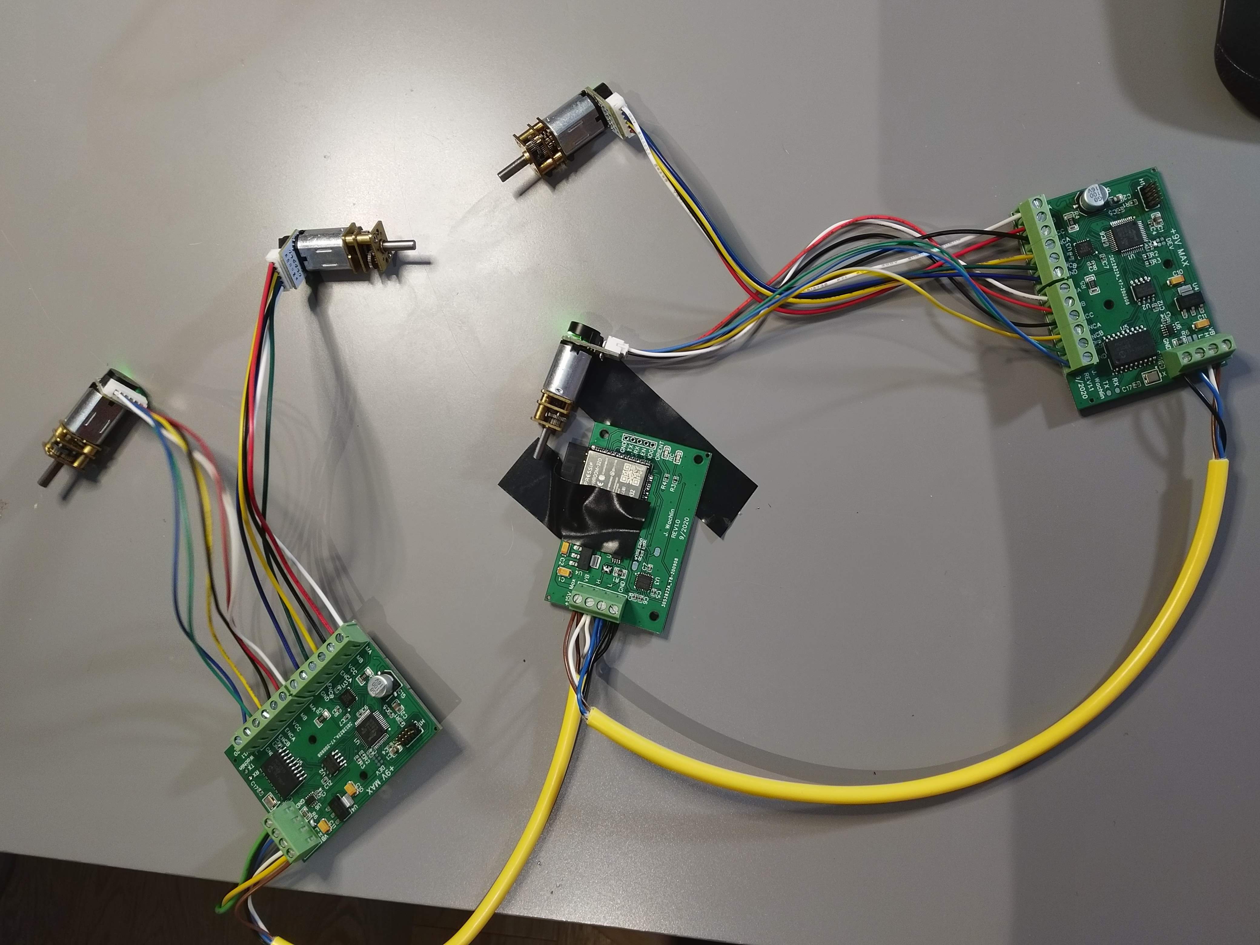
Although a square clearly is an odd shape for the backbone, it provides copious space to mount all of the electronics. With four legs, we need 4 dual motor controllers. We also have the ESP32 main controller in the center. All of these PCBs are ziptied to the sheet. I only have 6 motors so far, 1 of which is 50:1 (the rest are 150:1), so I can't test it fully yet.
![]()
I did however, run motion primitives on all 3 controllers with attached motors and it works as expected. As per the CAN ICD, I added a message to set the motor ticks-per-revolution, so I can configure the one controller with the 50:1 gearmotor to still follow the motion primitive properly, and that works great.
For now, I am waiting on more motors and mounting screws, and then I'll be able to assemble it. I may even be able to get a 3-legged walker going first.
Motion PlaybackMany industrial robots meant to operate near people (so called co-bots) have a mode where the user can move around the arm, it saves the motion, then it plays it back. Since this motor controller sends its position in telemetry feedback periodically to the ESP32 main controller, we can do something like this.
I wrote this setup all in Arduino. Basically, we want to periodically save keyframes which consist of the time and the positions of both motors. In order to save memory, we filter out keyframes that are too similar to the previous keyframe. Then, on playback, we command the keyframes at the appropriate time. A better setup might interpolate between keyframes and get less jerky motion, but this demo does show the promise of this use case.
The code to perform this is here. It is not pretty, but gets the job done.
#include <CAN.h> #include "dual_motor_can.h" #define CAN_RX_PIN 4 #define CAN_TX_PIN 5 #define LED2_PIN 16 #define FRONT_LEFT (1) #define FRONT_RIGHT (2) #define REAR_LEFT (4) #define REAR_RIGHT (3) #define MOTOR_0 (0) #define MOTOR_1 (1) #define TICKS_PER_REV (4200.0) // 28 CPR, 150:1 #define NUM_MOTORS (2) #define NUM_DEVICES (5) // Include main controller #define MAX_FRAMES (1000) #define FRAME_MIN_DELTA_DEG (3.0) typedef enum { NONE, RECORD, PLAYBACK } STATE; typedef struct { float m_0; float m_1; uint32_t time_since_start; } keyframe_t; typedef struct { uint16_t num_frames; uint16_t current_frame; uint32_t start_time; keyframe_t frames[MAX_FRAMES]; } profile_t; static volatile STATE state = NONE; static volatile uint32_t record_start_time = 0; static volatile uint32_t playback_start_time = 0; static volatile bool frame_received = false; static can_frame_t frame; static profile_t profiles[NUM_DEVICES]; static void reset_profiles(void) { // Command to open loop duty mode so it doesn't fight send_duty_command(2, 0, 0); delay(25); send_duty_command(2, 1, 0); delay(25); for (int i = 0; i < NUM_DEVICES; i++) { profiles[i].num_frames = 0; profiles[i].current_frame = 0; profiles[i].start_time = 0; for (int j = 0; j < MAX_FRAMES; j++) { profiles[i].frames[j].m_0 = 0.0; profiles[i].frames[j].m_1 = 0.0; profiles[i].frames[j].time_since_start = 0; } } } void setup() { Serial.begin(115200); pinMode(LED2_PIN, OUTPUT); digitalWrite(LED2_PIN, LOW); Serial.println("CAN position control demo"); CAN.setPins(CAN_RX_PIN, CAN_TX_PIN); // start the CAN bus at 1000 kbps if (!CAN.begin(1000E3)) { Serial.println("Starting CAN failed!"); while (1); } reset_profiles(); delay(2000); // register the receive callback CAN.onReceive(onReceive); } void loop() { static uint32_t last_time = 0; uint32_t current_time = millis(); if (current_time - last_time > 1000) { digitalWrite(LED2_PIN, !digitalRead(LED2_PIN)); last_time = current_time; } if (Serial.available()) { char c = Serial.read(); if ( c == 'r') { Serial.println("Recording"); state = RECORD; record_start_time = current_time; reset_profiles(); } else if (c == 'p') { Serial.println("Playing back"); state = PLAYBACK; playback_start_time = current_time; for (int i = 0; i < NUM_DEVICES; i++) { profiles[i].current_frame = 0; } } } // playback if needed if (state == PLAYBACK) { uint32_t time_since_start = current_time - playback_start_time; for (int i = 0; i < NUM_DEVICES; i++) { uint16_t num_frames = profiles[i].num_frames; uint16_t current_frame = profiles[i].current_frame; if (current_frame == num_frames || current_frame >= MAX_FRAMES) { continue; } if (time_since_start >= profiles[i].frames[current_frame].time_since_start) { // Send commands Serial.print("Sending device "); Serial.print(i); Serial.print(" frame "); Serial.println(current_frame); send_position_command(i, 0, profiles[i].frames[current_frame].m_0); delay(25); send_position_command(i, 1, profiles[i].frames[current_frame].m_1); delay(25); profiles[i].current_frame++; } } } if (state == RECORD && frame_received) { can_message_id_t msg_id; msg_id.raw_id = frame.id; // Unpack unpack_can_message(&msg_id); if (msg_id.can_msg_type == CAN_MSG_TYPE_INFO && msg_id.can_class == CAN_MSG_CLASS_INFO_TELEMETRY && msg_id.can_index == CAN_MSG_INDEX_INFO_POSITION) { uint8_t device = msg_id.can_device; if (device >= NUM_DEVICES) { return; } int32_t position_0, position_1; memcpy(&position_0, &frame.data[0], 4); memcpy(&position_1, &frame.data[4], 4); uint32_t frame_index = profiles[device].current_frame; if (frame_index >= MAX_FRAMES) { Serial.print("Frames full for device "); Serial.println(device); return; } if (frame_index == 0) { profiles[device].start_time = current_time; } float pos_0 = 360.0 * position_0 / (TICKS_PER_REV); // Save position in degrees float pos_1 = 360.0 * position_1 / (TICKS_PER_REV); // Save position in degrees bool save_frame = true; if (frame_index > 0) { // Only save frames with a big enough difference save_frame = false; if (abs(pos_0 - profiles[device].frames[frame_index - 1].m_0) > FRAME_MIN_DELTA_DEG || abs(pos_1 - profiles[device].frames[frame_index - 1].m_1) > FRAME_MIN_DELTA_DEG) { save_frame = true; } } if (save_frame) { //Save frame Serial.print("Saving device "); Serial.print(device); Serial.print(" frame "); Serial.println(frame_index); profiles[device].frames[frame_index].m_0 = pos_0; // Save position in degrees profiles[device].frames[frame_index].m_1 = pos_1; profiles[device].frames[frame_index].time_since_start = current_time - profiles[device].start_time; profiles[device].current_frame++; profiles[device].num_frames++; } } } frame_received = false; } void onReceive(int packetSize) { frame.id = CAN.packetId(); frame.dlc = CAN.packetDlc(); if (frame.dlc > 8) { frame.dlc = 8; } for (int i = 0; i < frame.dlc; i++) { frame.data[i] = CAN.read(); } frame_received = true; } -
Motion Primitives
09/27/2020 at 18:48 • 0 commentsOverview
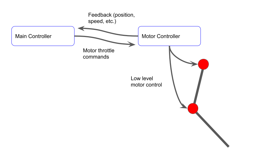
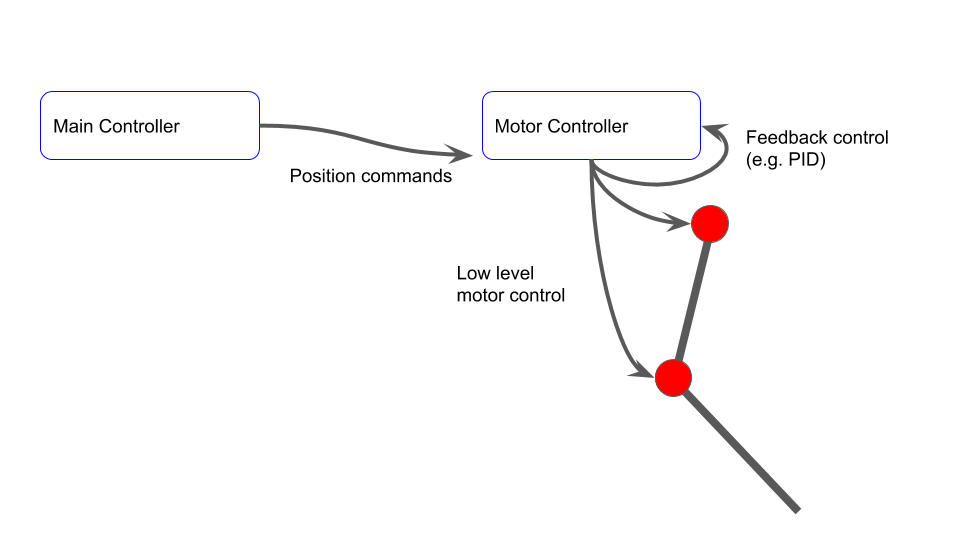
In robotics, online motion planning can be computationally intensive and/or add significant network load. To avoid this, motion primitives are sometimes used. The concept is that the higher level controller can command pre-determined trajectories that the lower level "local" controller can implement. To understand this better, first consider the following picture. Here, the main controller is doing the lower level control of the motors. It receives information about the motor (position, speed, etc.) and calculates motor throttle commands to the motor controller. The motor controller then does the low level control (e.g. PWM control). The communication between the main controller and motor controller must be fast for this to work. In addition, it requires significant computation on the main controller.
![]()
The next option is to offload the lower-level position control to the local controller, but still perform the motion planning on the main controller. This is what I've previously shown, where the ESP32 commands positions over the CAN bus to the dual motor controller. This works, but as the system has more and more motors (currently, we can address 16 motors), the main controller has to work harder to provide near real-time position commands to track trajectories. It could also potentially overload the CAN bus.
![]()
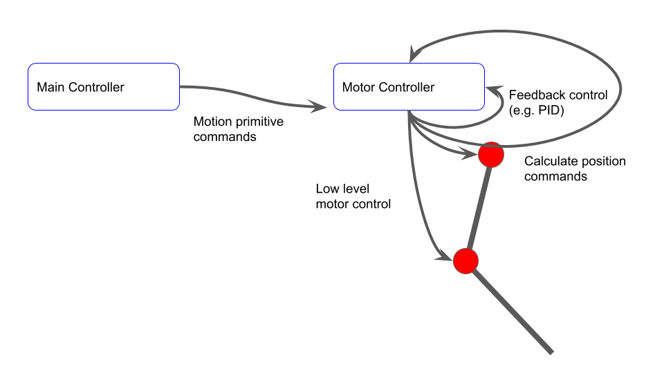
Finally, consider a motion primitive approach. Here, the motion controller simply tells the local controller to follow a pre-determined profile. The local controller then calculates its own position commands online, and controls the motor to follow the trajectory. This can potentially fully offload the main controller and the CAN bus.
![]()
While the concept is simple, implementation is more difficult. We will dig into the implementation next.
ImplementationThankfully, we already have much of the supporting structure needed to implement simple motion primitives. Namely, we have the structure to unpack CAN messages, change control modes, and calculate inverse kinematics of a two-joint leg.
In general, we will need a set of keypoints (provided in cartesian space for ease of understanding), and timing information of each of the keypoints. The primitives will be assumed to be periodic. We want the main controller to be able to slightly modify the primitive if needed. For example, we may want to stretch out a motion in one direction, change the period, or change the phase of the motion (time offset). We also may want to invert the motion to support left vs. right legs. I therefore created a few structures that help define the motion.
typedef struct
{
	float x;
	float y;
	float t_part;
} keyframe_t;

typedef struct
{
	uint8_t num_keyframes;
	uint8_t invert;
	float tau; // period
	float t_offset;
	keyframe_t frames[MAX_NUMBER_KEYFRAMES];
} primitive_t;
I started with a single example primitive, although it should be clear that adding further primitives is straightforward. We have 8 keyframes here. The motion is sort of a pointy, stretched rectangle, with positions in mm. Note that based on the t_part of each keyframe, the section from frame 4 to 5 is the slowest. The thought is that this could be a walking/crawling motion where the leg moves slower while pushing against the ground and faster in mid-air.
void motion_primitive_init(void)
 {
	// Leg straight, motors at zero is leg straight down +x. Forward is +y

	// t_part must be always increasing, never > 1.0. Must be a cyclical motion primitive

	// Curved rectangle primitive
	primitives[0].num_keyframes = 8;
	primitives[0].tau = 2.0;
	primitives[0].t_offset = 0.0;
	primitives[0].invert = 0;
	primitives[0].frames[0].t_part = 0.0 / primitives[0].tau;
	primitives[0].frames[0].x = 0.07;
	primitives[0].frames[0].y = 0.00;

	primitives[0].frames[1].t_part = 0.2 / primitives[0].tau;
	primitives[0].frames[1].x = 0.07;
	primitives[0].frames[1].y = 0.06;

	primitives[0].frames[2].t_part = 0.3 / primitives[0].tau;
	primitives[0].frames[2].x = 0.083;
	primitives[0].frames[2].y = 0.065;

	primitives[0].frames[3].t_part = 0.4 / primitives[0].tau;
	primitives[0].frames[3].x = 0.086;
	primitives[0].frames[3].y = 0.065;

	primitives[0].frames[4].t_part = 0.5 / primitives[0].tau;
	primitives[0].frames[4].x = 0.09;
	primitives[0].frames[4].y = 0.06;

	primitives[0].frames[5].t_part = 1.6 / primitives[0].tau; // Slower on back stroke
	primitives[0].frames[5].x = 0.09;
	primitives[0].frames[5].y = 0.0;

	primitives[0].frames[6].t_part = 1.8 / primitives[0].tau;
	primitives[0].frames[6].x = 0.086;
	primitives[0].frames[6].y = -0.05;

	primitives[0].frames[7].t_part = 1.9 / primitives[0].tau;
	primitives[0].frames[7].x = 0.083;
	primitives[0].frames[7].y = -0.05;
 }
We handle CAN commands for this as shown below. Primitives require both motors. We have the normal control loop in position control mode, and a separate loop periodically updates the desired position according to the primitive profile. From the CAN frame, we determine which primitive to use, the period "Tau" in ms, a time offset in ms, and an indication if the profile should be run inverted (not backwards in time, reversed in joint space.)
else if(msg.can_index == CAN_MSG_INDEX_CMD_PRIMITIVE)
{
	 // Primitives affect both motors
	int16_t tau_ms = 0;
	int16_t t_offset_ms = 0;
	uint8_t primitive_index = can_frame.data[0];
	memcpy(&tau_ms, &can_frame.data[1], 2);
	memcpy(&t_offset_ms, &can_frame.data[3], 2);
	uint8_t invert = can_frame.data[5];
	motion_primitive_set_index(primitive_index);
	motion_primitive_set_timing(primitive_index, (float) tau_ms * 0.001, (float) t_offset_ms * 0.001, invert);
	set_control_mode(PRIMITIVE, 0);
	set_control_mode(PRIMITIVE, 1);
}
Within a software timer, we periodically calculate the joint space positions and command the motors.
static void vPrimitivesTimerCallback( TimerHandle_t xTimer )
  {
	int32_t i;
	// Only calculate if all primitive
	for(i=0; i < NUMBER_MOTORS; i++)
	{
		if(control_type[i] != PRIMITIVE)
		{
			return;
		}
	}

	pos_cartesian_t cart_pos;
	pos_joint_space_t js_pos;

	motion_primitive_get_position(&cart_pos.x, &cart_pos.y);

	calculate_ik(&leg, &js_pos, cart_pos);

	if(motion_primitive_is_inverted())
	{
		 js_pos.thigh_angle_rad = -js_pos.thigh_angle_rad;
		 js_pos.knee_angle_rad = -js_pos.knee_angle_rad;
	}

	set_motor_position(RAD_TO_DEG * js_pos.thigh_angle_rad, 0);
	set_motor_position(RAD_TO_DEG * js_pos.knee_angle_rad, 1);
  }
Within the motion primitives library, we generate these positions by linearly interpolating between keypoints, while accounting for global time offsets (used to sync all controllers), and local primitive time offsets.
 void motion_primitive_get_position(float * x, float * y)
 {
	// First find global time,taking into account time syncs and primitive local offsets
	float current_t = 0.001 * (xTaskGetTickCount() - time_offset) - primitives[primitive_index].t_offset;

	float time_in_cycle = fmod(current_t, primitives[primitive_index].tau);
	float time_in_cycle_part = time_in_cycle / primitives[primitive_index].tau; // Prevent further mults

	// Now find where we are in the cycle and linearly interpolate
	int i;
	for(i = 1; i < primitives[primitive_index].num_keyframes; i++)
	{
		// Are we between keyframes?
		if(time_in_cycle_part >= primitives[primitive_index].frames[i-1].t_part && time_in_cycle_part < primitives[primitive_index].frames[i].t_part)
		{
			// Last value plus section of new value
			float dt = (time_in_cycle_part - primitives[primitive_index].frames[i-1].t_part);
			float d_section_dt = 1.0 / (primitives[primitive_index].frames[i].t_part - primitives[primitive_index].frames[i-1].t_part);
			*x = primitives[primitive_index].frames[i-1].x + (dt * (primitives[primitive_index].frames[i].x - primitives[primitive_index].frames[i-1].x) * d_section_dt);
			*y = primitives[primitive_index].frames[i-1].y + (dt * (primitives[primitive_index].frames[i].y - primitives[primitive_index].frames[i-1].y) * d_section_dt);
			return;
		}
		// Are we at the end, and after last keyframe
		if(i == (primitives[primitive_index].num_keyframes-1) && time_in_cycle_part >= primitives[primitive_index].frames[i].t_part)
		{
			// Last value plus section of new value
			float dt = (time_in_cycle_part - primitives[primitive_index].frames[i].t_part);
			float d_section_dt = 1.0 / (1.0 - primitives[primitive_index].frames[i].t_part);
			*x = primitives[primitive_index].frames[i].x + (dt * (primitives[primitive_index].frames[0].x - primitives[primitive_index].frames[i].x) * d_section_dt); // Cyclical, so zero index is next frame at end
			*y = primitives[primitive_index].frames[i].y + (dt * (primitives[primitive_index].frames[0].y - primitives[primitive_index].frames[i].y) * d_section_dt);
			return;
		}
	}
 }
That is all there is to it!
DemoTo prepare to test this, I also made some updates to support multiple dual motor controllers on the same network. I provided 3 solder jumpers on the PCB that are used to set the device index in a binary representation. The main controller is index 0, and the first dual motor controller is index 1 if all solder jumpers are open. I soldered one on one controller to set it to index 2. I can then string together many dual motor controllers on the same bus.
![]()
The main controller has a very simple job. It simply sends a single command to each controller to begin motion primitive 0. This is done as follows. Devices 1 and 2 are commanded to run primitive #0, with a period of 2s. Device 2 has a time offset of 0.3s. Device 1 is inverted.
#include <CAN.h>
#include "dual_motor_can.h"

#define CAN_RX_PIN      4
#define CAN_TX_PIN      5
#define LED2_PIN              16

void send_primitive_command(uint8_t device, uint8_t primitive, uint8_t invert, int16_t tau_ms, int16_t t_offset_ms)
{
  if(device > 7)
  {
    return;
  }


  uint32_t id = (CAN_MSG_TYPE_CMD << CAN_MSG_TYPE_SHIFT);
  id |= (CAN_MSG_CLASS_CMD_CONTROL << CAN_MSG_CLASS_SHIFT);
  id |= (CAN_MSG_INDEX_CMD_PRIMITIVE << CAN_MSG_INDEX_SHIFT);
  id |= (device << CAN_MSG_DEVICE_SHIFT);

  uint8_t buffer[6];
  buffer[0] = primitive;
  memcpy(&buffer[1], &tau_ms, 2);
  memcpy(&buffer[3], &t_offset_ms, 2);
  buffer[5] = invert;

  CAN.beginPacket(id);
  CAN.write(buffer, 6);
  CAN.endPacket();
}

void setup() {
  Serial.begin(115200);

  Serial.println("CAN position control demo");

  CAN.setPins(CAN_RX_PIN, CAN_TX_PIN);

  // start the CAN bus at 1000 kbps
  if (!CAN.begin(1000E3)) {
    Serial.println("Starting CAN failed!");
    while (1);
  }

  delay(2000);
  send_primitive_command(1, 0, 1, 2000, 0); // Inverted
  delay(20);
  send_primitive_command(2, 0, 0, 2000, 300);
}

void loop() {
  // Do nothing
  delay(1000);
}
After testing that this system works as expected, I attached the 3D printed frame and legs I had previously made. Using tape, zipties, and cardboard, I also hacked together a janky "tail dragger" frame to stabilize the system.
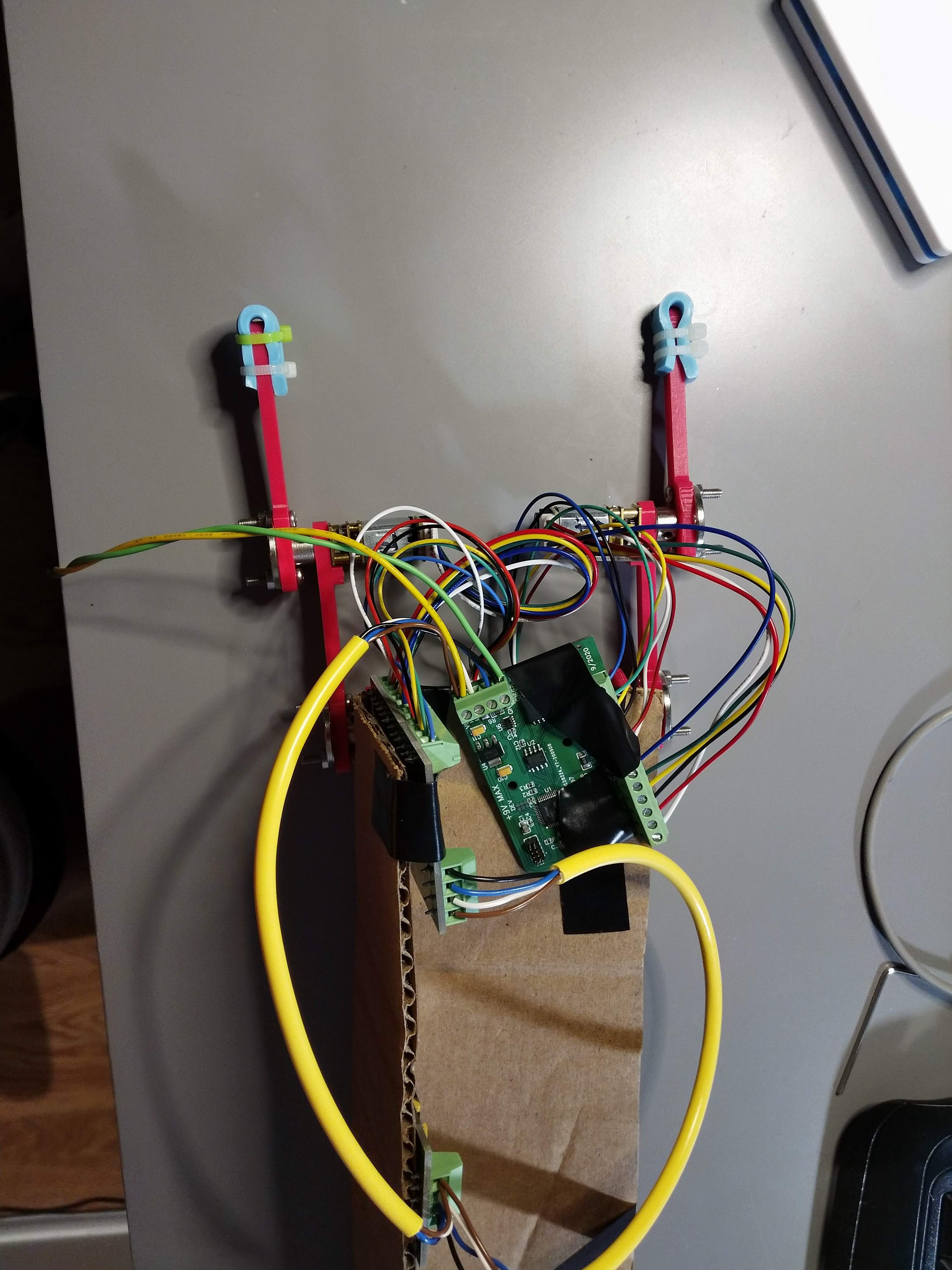
![]()
![]()
The video below shows the motion in the air. It is clear that the motion is slower pulling back, and that the two legs run at a time offset. Again, since we are using a motion primitive, this motion is occurring with no load on the main controller or CAN bus.
The next video shows the system on the ground. Clearly it is failing to move properly, but not bad for the first attempt.
Future Upgrades- Precompute motion in joint space to reduce online inverse kinematics computation
- Different interpolation? Interpolate in joint space?
- Additional motion primitives
- Modify motion primitive to achieve crawling
- Support further primitive parameterization
- Support running primitives backwards in time
-
Revision 1 Hardware Testing and Dumb Demo
09/27/2020 at 01:15 • 0 commentsHardware
The new version of the motor controller and the first version of the ESP32-based main controller arrived this week, and I've been testing them out. The hardware turned out nicely. The screw terminals and better labeling all help the design look more professional.
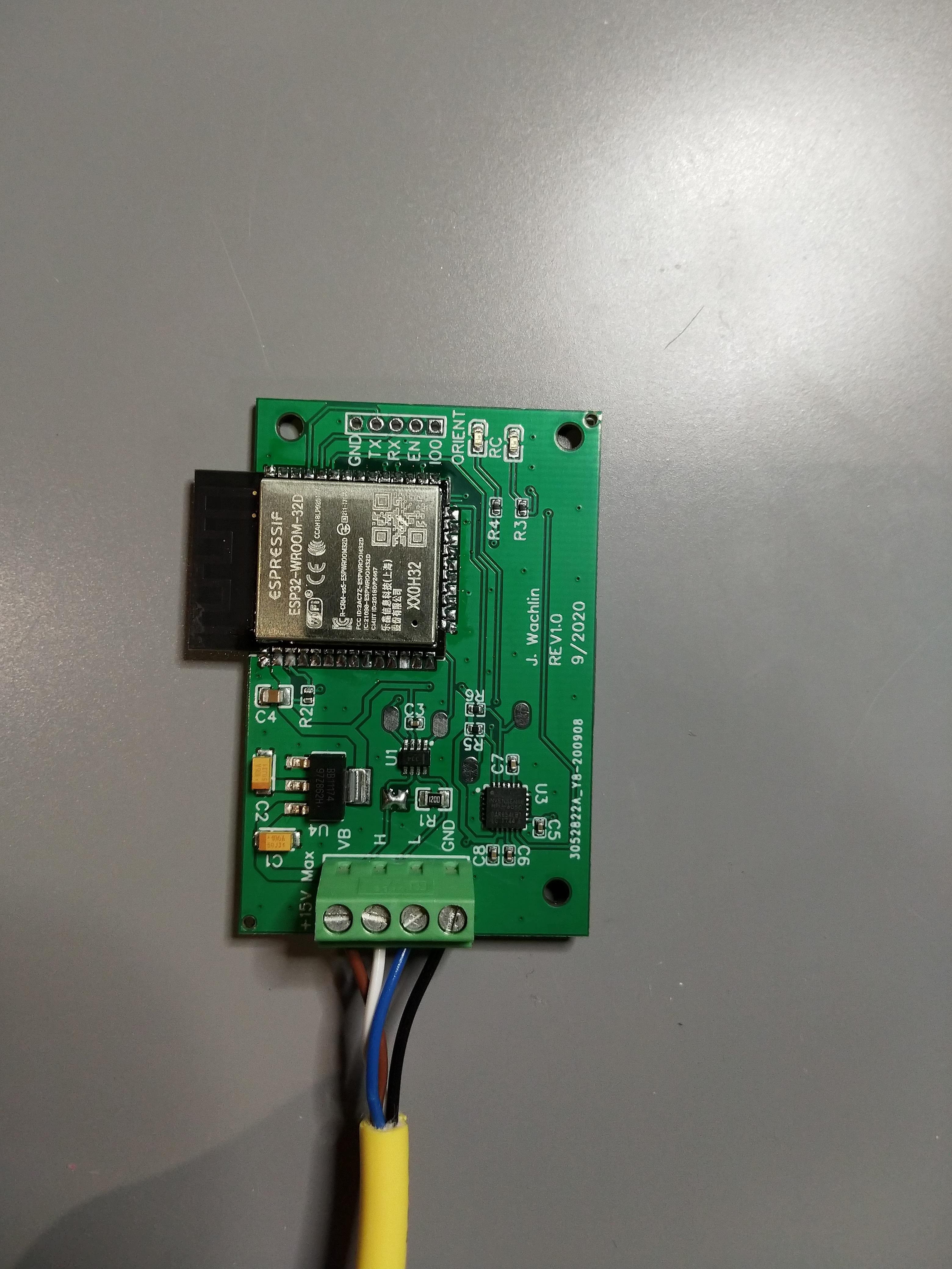
The ESP32-based main controller is shown below. It is a simple board, with the ESP32 for computation and wireless communications, a MPU6050 IMU, and a CAN transceiver.
![]()
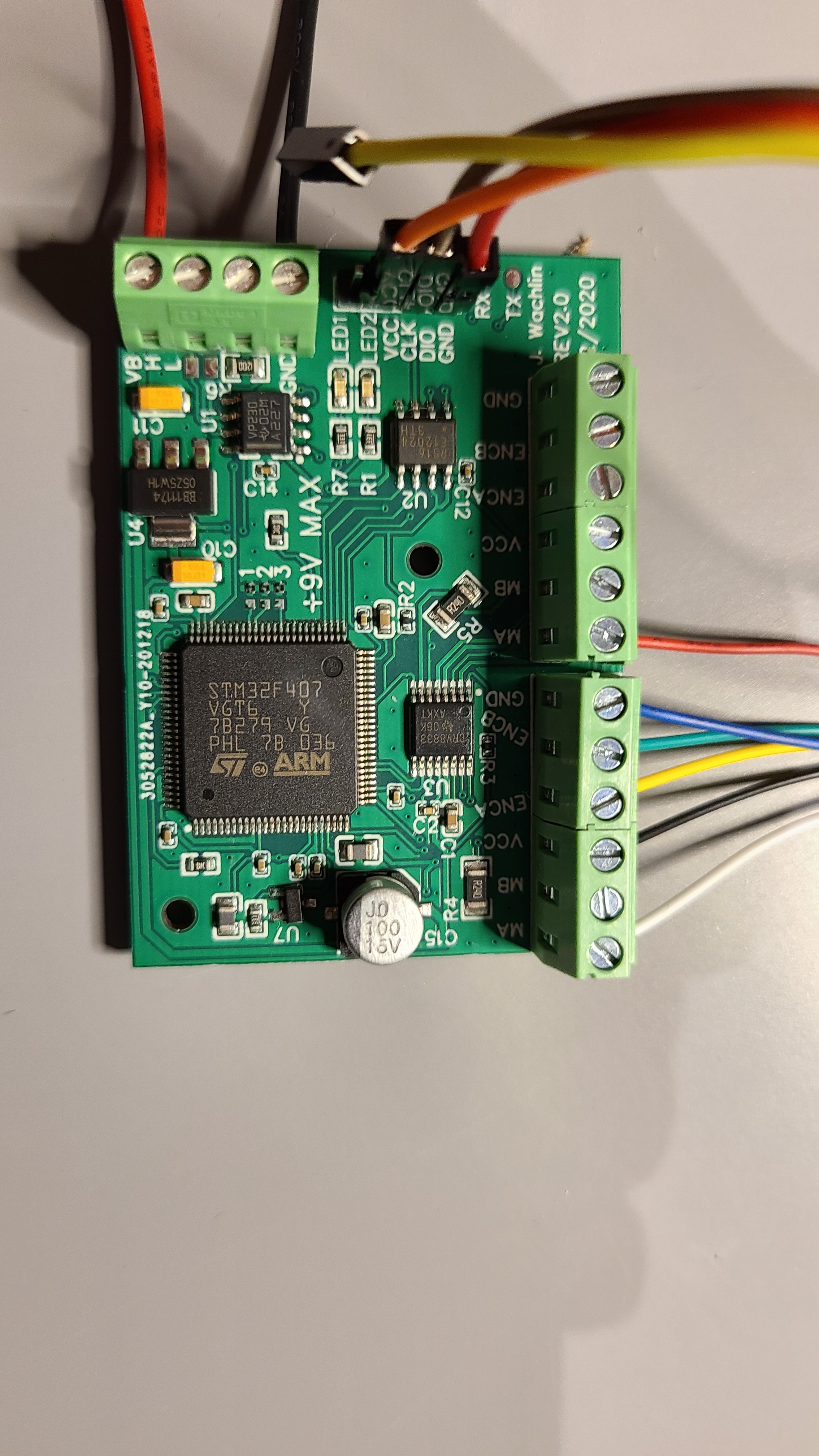
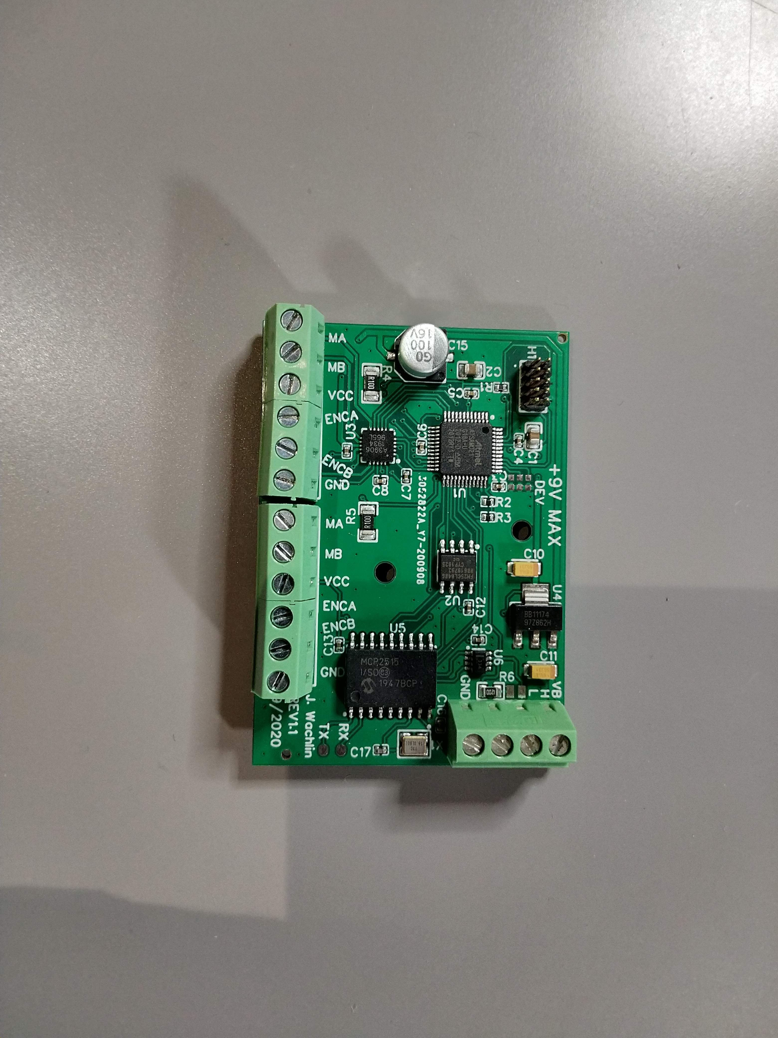
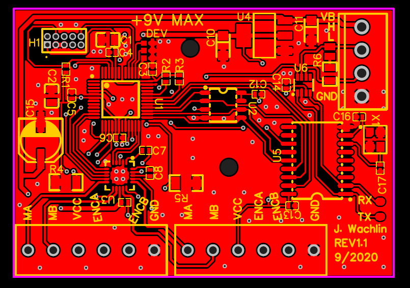
Next, let's look at the Rev 1.1 motor controller. The screw terminals and bulk capacitor are the most obvious changes, but the most important update is the 16MHz crystal added to the MCP2515 CAN controller.
![]()
NetworkingWith a main controller, and working CAN controller on the motor controller, I was able to move forward with the CAN communication layer. In a previous log, I explained how we split the bits of the frame IDs to indicate different messages. I also said the network would run at 500kbps. However, I bumped that up to 1Mbps, because why not? I added a software timer to send motor telemetry at 20Hz. For now, this is the motor position and current, but I plan to add more information in the future.
I also added more support for various control schemes. Each received CAN frame is put onto a FreeRTOS queue, and parsed in the CAN bus task. For each different received control command, the control approach is changed, so that the main controller can switch from closed loop position commands to open loop duty cycle commands without issue.
The video below shows the first time the networking was working. The main controller was sending position commands, and the motor was moving correctly.
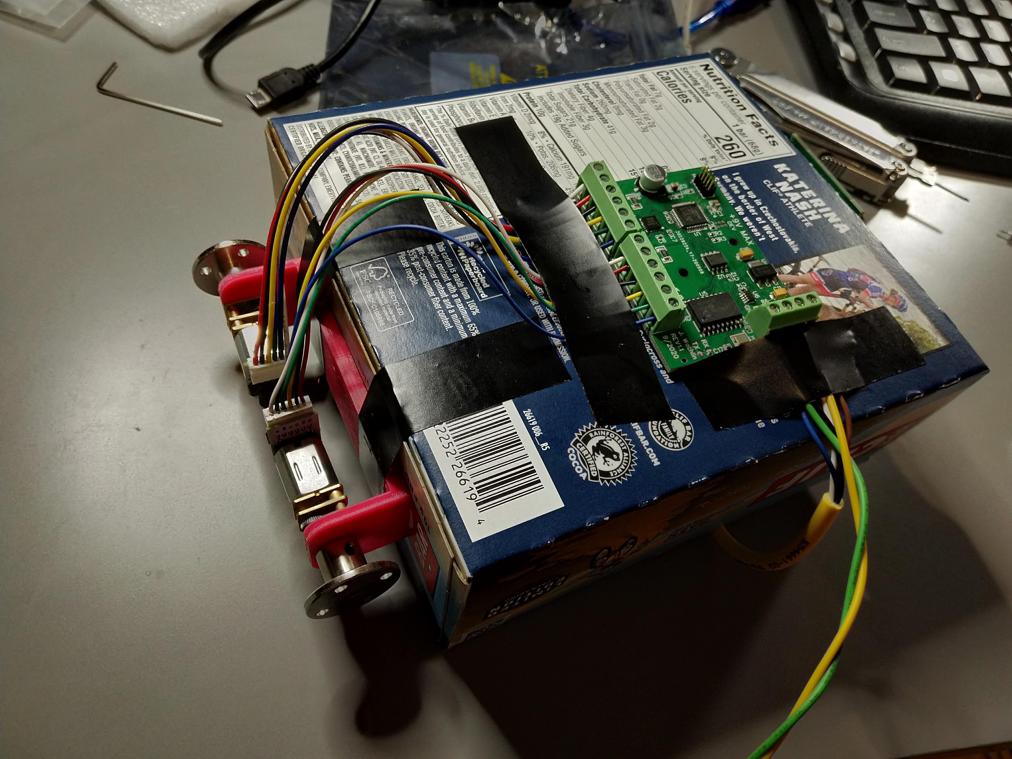
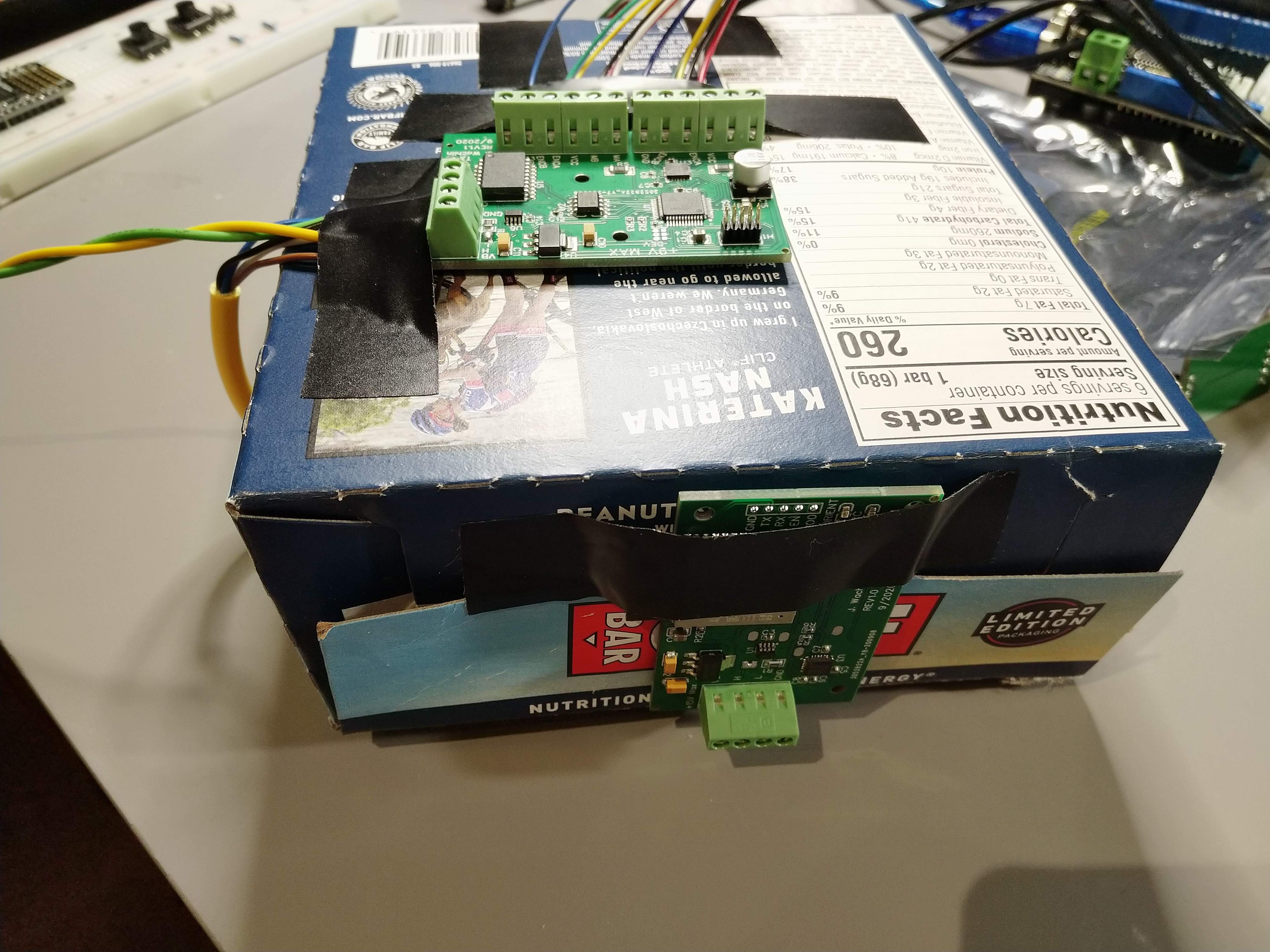
Unbelievably Dumb DemoAs an example of soft real-time interaction between the main controller and the dual motor controller board, I set up an "inverted pendulum" self-balancer using a Clif Bar box as the main structure. The main controller is taped to the top, and there is a proportional controller on roll (and, differentially, yaw) that commands open loop duty cycle commands to the motors. I had selected these motors for the high torque needed to drive the joints in a small walker robot, so they are not fast. The metal hubs used as wheels also get no traction on the desk and slip a lot.
The motors are mounted on a 3D printed frame I made in preparation for building a walking robot, which is then taped onto the box. Both PCBs are taped on as well, and a power tether runs to my power supply.
The peanut butter banana bars are the good ones.
![]()
![]()
What could possibly go wrong?
In the video, I clearly have to help it stay upright. With limited traction and slow motors, it is pretty limited. The hardware is clearly working though, which is what really matters here!
Next Steps- Run system on a battery
- Control 2+ dual motor controllers from main controller
- Continue to add software support
- Motion primitives
- Time synchronization
- Position zero-ing command
- Further telemetry
- Improve CAN RX handling approach
- Speed control
- Build more demo projects
- SCARA arm/plotter
- Crawling robot
- Bipedal walking robot?
- Quadruped walking robot?
- RC drift car w/ torque vectoring and traction control (using faster motors)
-
Redesign and Main Controller
09/07/2020 at 19:05 • 0 commentsDual CAN Motor Controller Redesign
While most of the V1.0 dual CAN motor controller works, the CAN interface does not. In addition, there were a number of usability improvements I wanted to make for a V1.1 update. I used JLCPCB as the assembly service, and EasyEDA for its clean interface to that assembly service. Their assembly service only supports a limited number of components and only single-sided SMD parts. Therefore I will assemble all the through hole parts myself.
The updates were:
- Add a 16MHz crystal to the MCP2515 to fix the CAN issue
- Add pads at logic level CAN TX/RX for debugging support
- Label all external connections on silkscreen
- Label maximum input voltage
- Add optional CAN 120 Ohm termination resistor with solder jumper
- Add 3-bit device numbering with solder jumpers to address devices without firmware changes
- The first version just used 0.1" pitch through holes for the motor and power/CAN connections. On V1.1 I chose actual screw terminal connections so wires don't need to be soldered permanently in
- Add holes that can be used for mounting
- Add bulk capacitance for motor controller (doesn't seem strictly necessary, but not a bad idea to have)
The PCB got slightly larger due mainly to the larger external connectors. The image below shows the updated layout. PDFs of the layout and schematic have also been uploaded to the project page.
![]()
Main Robot ControllerThese dual motor controllers are meant to be peripherals on a larger network. They receive higher level commands from some external device over CAN, and handle the low-level motor control. I therefore built an example simple main controller. The main requirements are an attitude sensor and sufficient computational capability to theoretically run complex walking gait controllers.
For this design I used the ESP32. With 2 cores at 240MHz, it has the computational capability to run fairly complex control schemes. It also has a built in CAN controller. Finally, it supports wireless connectivity so I can send commands remotely if desired. I also used the MPU6050 as an attitude sensor. I can either use its internal sensor fusion, or write my own Kalman filter to fuse the accelerometer and gyroscope data.
Just like the dual motor controller, I made sure to label all external pins, add CAN TX/RX pads for debugging, as well as I2C debugging support. It has 2 LEDs which tentatively will indicate when it has good wireless communication and when it has a good orientation estimate.
![]()
Thanks to JLCPCB's insanely cheap assembly service, I bought 10 of each board for ~$200 total. Getting each board nearly fully built and delivered in <2 weeks for ~$10/board is crazy!
-
CAN Bus Network Layer and Hardware Fix Failure
09/06/2020 at 18:18 • 0 commentsWith the project now able to control two motors well, and much of the supporting code for more complicated use cases written, the next step is to set up the communication between devices. For this, the Controller Area Network (CAN) bus is used. Originally developed for automotive use, CAN allows for relatively high-speed, robust, and long-range multi-master communication. It uses two wires which are differentially driven by a dedicated transceiver. I used the TCAN334 here. While some microcontrollers have a CAN controller built in, the ATSAMD21 does not, so I used the ubiquitous MCP2515. The MCP2515 is commonly used in all sorts of low-cost hobbyist (and serious commercial) CAN applications. It has an SPI interface to the ATSAMD21. The two steps here are writing the code to support commands over CAN, and wiring up the physical interface.
CAN Network Software ImplementationThe Wikipedia page for CAN bus is very enlightening if you are not familiar with how CAN works. CAN is a multi-master protocol, so any device on the bus can send a frame at any time. Each frame has many parts, but the most important are the Identifier (ID) and data sections. The ID is either a 11 or 29 bit value that indicates what is in the message. The data section then holds 0-8 bytes of message data. At the lowest level, the IDs don't mean anything, it is up to the developer to determine how they should be set up. To de-conflict messages, lower ID values are sent first and are thus higher priority messages. When determining how to lay out the IDs, this should be accounted for and lower IDs used for higher priority messages. Finally, different nodes on the bus should never try to send frames with the same ID.
Therefore, we take some inspiration from the way that the FIRST Robotics Competition lays out IDs using sections of the ID bitfield. Unlike FRC, we will use standard (11 bit) identifiers and communicate at 500kbps (may increase speed in the future). We use the most significant bit as a message type identifier: either a command or info frame. Therefore, all commands are higher priority than all info messages. The next most significant 3 bits are a message class identifier. The next 3 most significant bits are message indices. Finally, the last 4 bits are device indices. For commands, the device index indicates the receiver. For info messages, the device index indicates the sender.
I then started to think about what messages I would want to send. These can and will be changed in the future but I started with the following:
#define CAN_MSG_TYPE_SHIFT				(10ul)
#define CAN_MSG_TYPE_MASK				(1ul << CAN_MSG_TYPE_SHIFT)

#define CAN_MSG_CLASS_SHIFT				(7ul)
#define CAN_MSG_CLASS_MASK				(7ul << CAN_MSG_CLASS_SHIFT)

#define CAN_MSG_INDEX_SHIFT				(4ul)
#define CAN_MSG_INDEX_MASK				(7ul << CAN_MSG_INDEX_SHIFT)

#define CAN_MSG_DEVICE_SHIFT			(0ul)
#define CAN_MSG_DEVICE_MASK				(15ul << CAN_MSG_DEVICE_SHIFT)

#define CAN_MSG_TYPE_CMD					(0)
#define CAN_MSG_TYPE_INFO					(1)

#define CAN_MSG_CLASS_CMD_CONTROL			(0)
#define CAN_MSG_CLASS_CMD_TIME				(1)
#define CAN_MSG_CLASS_CMD_SET_PARAM			(2)

#define CAN_MSG_INDEX_CMD_POSITION			(0)
#define CAN_MSG_INDEX_CMD_SPEED				(1)
#define CAN_MSG_INDEX_CMD_CURRENT			(2)
#define CAN_MSG_INDEX_CMD_PRIMITIVE			(3)

#define CAN_MSG_CLASS_INFO_TELEMETRY		(0)

#define CAN_MSG_INDEX_INFO_POSITION			(0)
#define CAN_MSG_INDEX_INFO_CURRENT			(1)
#define CAN_MSG_INDEX_INFO_SPEED			(2)
There are three obvious command classes I might want: control commands, time (for synchronization), and setting parameters. Then, within control I might want position, speed, current, or motion primitive commands.
Within info, there are numerous telemetry messages we could send. To start, I listed motor position, current, and speed.
This does not currently show how the data in these messages are packed, I will need to create an ICD for that.
The first one to implement support for is a position command. I will set up an Arduino Uno + CAN bus shield to generate and send position commands, and my controller board will act upon those commands. This message will be packed such that the first byte is the motor index (0 or 1), and the next 4 bytes are a float packed as little-endian. This frame is only 5 bytes long.
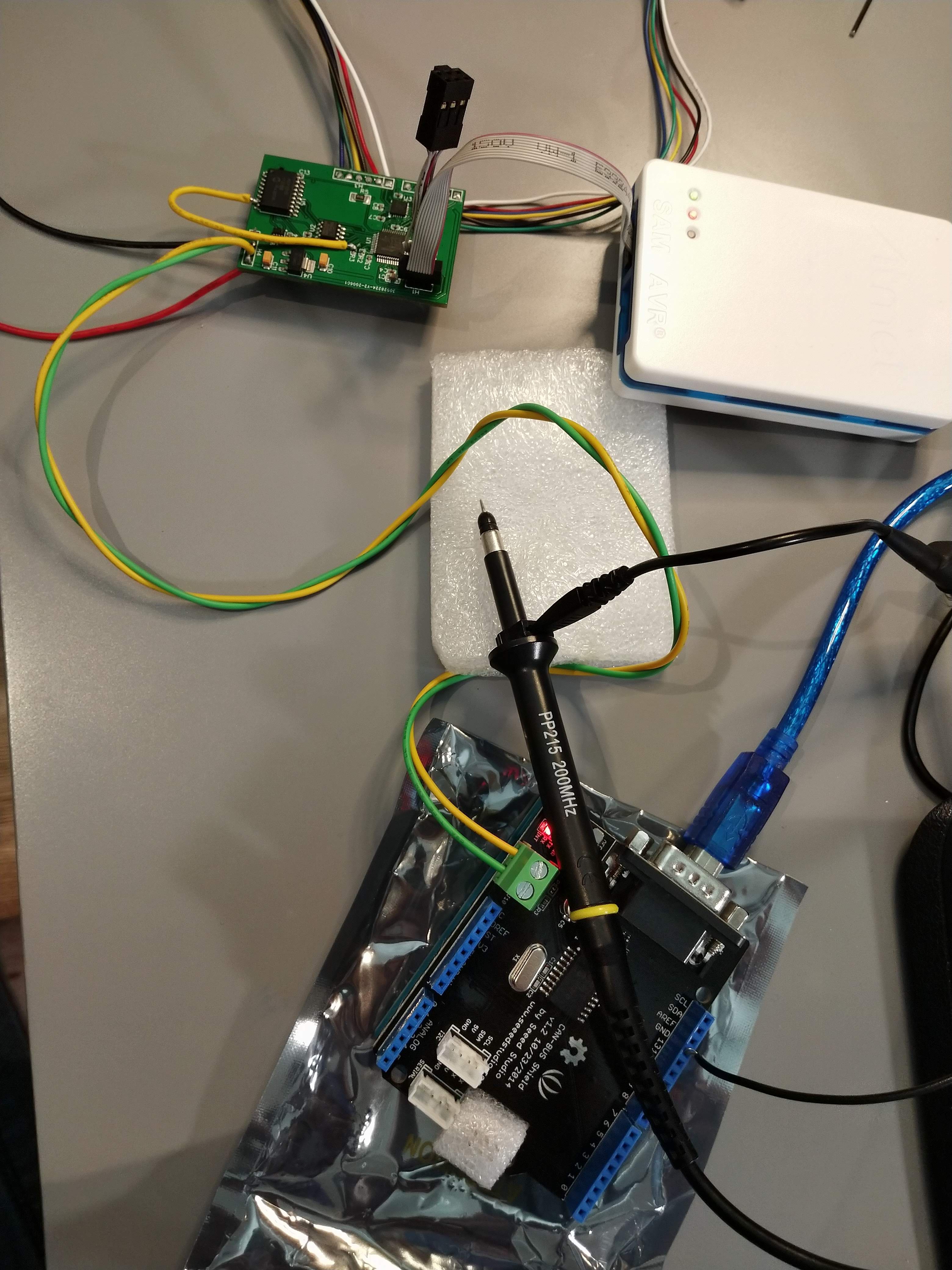
CAN Network WiringThe main reason I had held off on this step for so long was a design mistake I had made. I had forgotten to add the oscillator required by the MCP2515, which would surely cause it to not function correctly. To solve this on my current board, I realized one of the motor controller flag pins was mapped to the ATSAMD21 general clock #6. The MCP2515 can operate with either an oscillator or an external clock. I therefore could cut the trace to the motor controller and bodge wire the pin to the MCP2515 clock-in pin. The yellow wire on the PCB is doing this.
![]()
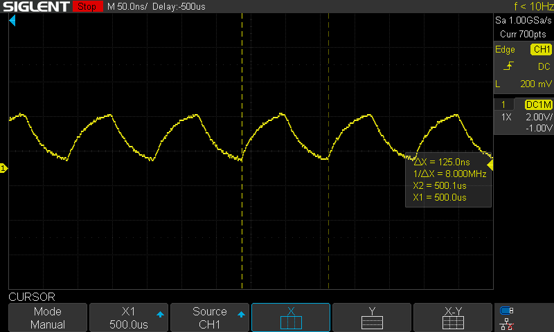
Unfortunately, when I probed the signal with my oscilloscope, the clock is a sawtooth, very not square. It is at the correct, desired 8Mhz. I suspected the controller may not be able to function properly because of this poor signal integrity. Note that the signal is poor with and without the bodge wire attached.
![]()
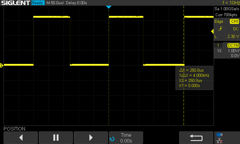
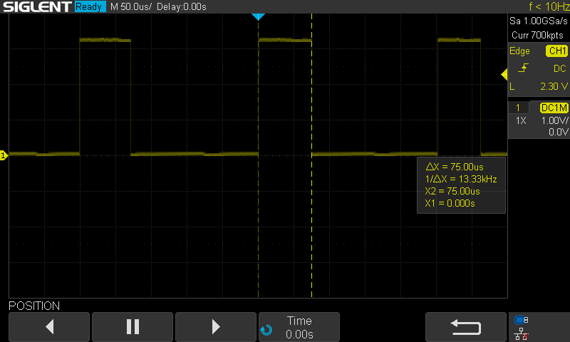
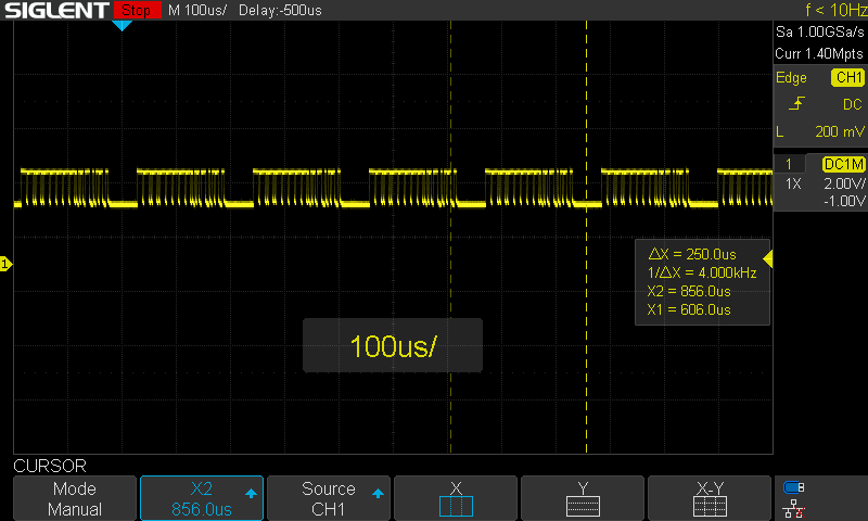
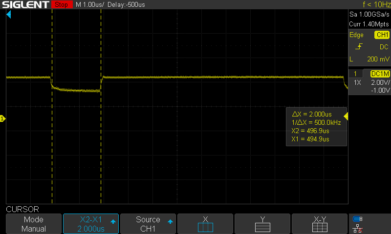
When I wired everything up, I set up an Arduino Uno with CAN bus shield to send motor 0 position commands every 2 seconds. However, when I probe the CANH line, it is clear that a message is being repeatedly sent at ~4kHz.
![]()
![]()
The network is not correctly terminated, with a 100 Ohm resistor on only one side (should be 120 Ohm on both sides), but in my experience such a short run should work regardless. This "spamming" of the network is a common error condition in CAN (depending on the settings of the CAN controller). There is no other device to acknowledge the frame, so it repeatedly sends the frame. This implies that the CAN controller or CAN transceiver on my PCB are not functioning properly. I double checked the polarity of the reset and standby pins for those, and they are correct. This error is likely due to the poor clock signal. I have some other ideas I can try, but I probably will have to do the redesign before I can move forward with the CAN setup.
-
Current Control to Virtual Model Control
09/05/2020 at 17:54 • 0 comments
The last log covered the implementation of position PID control, then inverse kinematics which allow the system to track a motion in the Cartesian space. As another demo, I tried increasing the frequency of actuation. This leg is hauling. This is really where this project is much better than hobby servos: it can go faster and all parameters can be tuned. Note I also bought some steel hubs which greatly reduce the backlash in the leg.![]()
Just as position control is a prerequisite for a tracking controller with inverse kinematics, those same inverse kinematics and current control are prerequisites for a Virtual Model/Impedance Controller.
The Virtual Model Controller implemented here is a simple Cartesian spring setup. The idea is that there are virtual springs attached between the real "foot" of the leg and some desired position for the leg to be. Based on the Hooke's Law for linear springs, we then calculate a desired force to apply to the foot. We then calculate the appropriate torque needed at each joint to apply that force. Depending on the environment, there may be nothing to push against to achieve that force, but this setup nonetheless allows for a pseudo-position control as well, as the foot will be "pulled" towards the desired position by the virtual springs. For ambulatory robots, this sort of controller is common, as it adds virtual elasticity which can help stabilize the walking controller.
![]()
In the simplest motor models, motor current is proportional to motor torque. In ambulatory robots, this is often used to achieve torque control via motor current control. This works well with high-quality motors, low friction, and minimal gearing. The cheap, highly geared motors I am using are not ideal, to say the least. Furthermore, I do not have directional current sensing, which during transitions between direction can cause issues. Nonetheless, we will look at how the implementation would be achieved.
Current ControlThe current control is implemented using the previously shown PID control library, but instead of providing encoder ticks inputs I use current in mA. Since I do not have directional current measurement, I don't want to allow the controller to command an opposite direction command, which could destabilize the controller. Instead, it clamps the command to zero. In reality, this should be OK, as the current will drop rapidly if command is set to zero. As a demo, I set a motor to drive +100mA and then -200mA periodically. The gifs below show the current being limited appropriately. It is not perfectly tuned, but is certainly working.
![]()
![]()
Note that unless the motor pushes against something, it likely will not reach the desired current, and will simply spin in the correct direction indefinitely. This can be a challenge with the virtual model controller. If the controller is not fast enough, the leg will move so much that instabilities in the controller can be reached.
Virtual Model ControllerAssuming that current control is linearly equivalent to torque control (again, not very true for these motors, but they are related) the next step is to be able to transform desired force in the Cartesian frame to desired torque in joint space. This is directly related to the inverse kinematics discussed previously. Ignoring friction, gravity, and other forces, the transformation uses the Jacobian, which here is the partial derivatives of the positions with respect to the motor orientations. The values of this matrix change as the leg moves, so it must be recalculated online. Then, the torque can be calculated from the forces with the transpose of the Jacobian.
The code for this looks like the following:
 void calculate_impedance_control(const impedance_control_params_t params, const leg_ik_t leg, const pos_joint_space_t current_pos, const pos_cartesian_t desired_pos, impedance_control_cmds_t * cmds)
 {
	pos_cartesian_t current_pos_cart;
	calculate_fk(&leg, ¤t_pos_cart, current_pos);

	// Calculate desired force from springs
	// TODO add damper
	float fx = params.k_eff * (desired_pos.x - current_pos_cart.x); // In N
	float fy = params.k_eff * (desired_pos.y - current_pos_cart.y);

	// Calculate jacobian
	float j_01 = -leg.calf_length_m * sin(current_pos.thigh_angle_rad + current_pos.knee_angle_rad);
	float j_00 = -leg.thigh_length_m * sin(current_pos.thigh_angle_rad) + j_01;
	float j_11 = leg.calf_length_m * cos(current_pos.thigh_angle_rad + current_pos.knee_angle_rad);
	float j_10 = leg.thigh_length_m * cos(current_pos.thigh_angle_rad) + j_11;

	// Calculate desired torque, tau_d = J^T * f_d
	float tau_hip = fx*j_00 + fy*j_10; // In N * m
	float tau_knee = fx*j_01 + fy*j_11;

	// Account for gear ratio
	tau_hip = tau_hip / params.gear_ratio;
	tau_knee = tau_knee / params.gear_ratio;

	// Calculate desired current to meet torque
	float current_hip = params.gain_current_per_torque * tau_hip;
	float current_knee = params.gain_current_per_torque * tau_knee;

	// Current controller outside of here
	cmds->hip_cmd_ma = current_hip * 1000.0;
	cmds->knee_cmd_ma = current_knee * 1000.0;
 }
The desired force is calculated, then the corresponding torque is calculated, then the appropriate motor current is determined. Not shown here is the current control that is finally applied.
Overall, this approach *sort of* works. As a test, I used the same desired circular motion as the desired position of the foot, then this impedance controller to pull the foot in that motion. It is not well tuned, and with these cheap motors with large gear ratios I don't expect good results but the leg does move approximately correctly. When I push and pull against the foot, it is more obvious how the controller wants the foot to move.
![]()
Next I will be working on the CAN bus network layer. On this version of the PCB, I forgot the crystal oscillator for the CAN controller, but I think I may be able to bodge wire a clock from the SAMD21 to the controller and get it to work.
CAN Controlled Dual Closed-Loop Motor Controller
Dual micro-gearmotor controller with CAN bus interface and onboard motion primitives