Close
0%
0%

#Atmega_screen

Glanceable information displayed on a LCD screen powered by a atmega328 and feed from a internet connected raspberry pi

Similar projects worth following
I'm a big fan of wearing a watch which is a rarity these days, I love the fact that you can look at a watch and get all the information you need. This is where I got the idea for atmega_screen. The information is feed from a python script that runs on raspberry pi. The information is pulled from several python json API depending on what information you want displaying.

I started with a arduino LCD shield which was great for displaying the infomation but found it quite limiting since you couldn't add anything to this package i.e LED's or speakers.

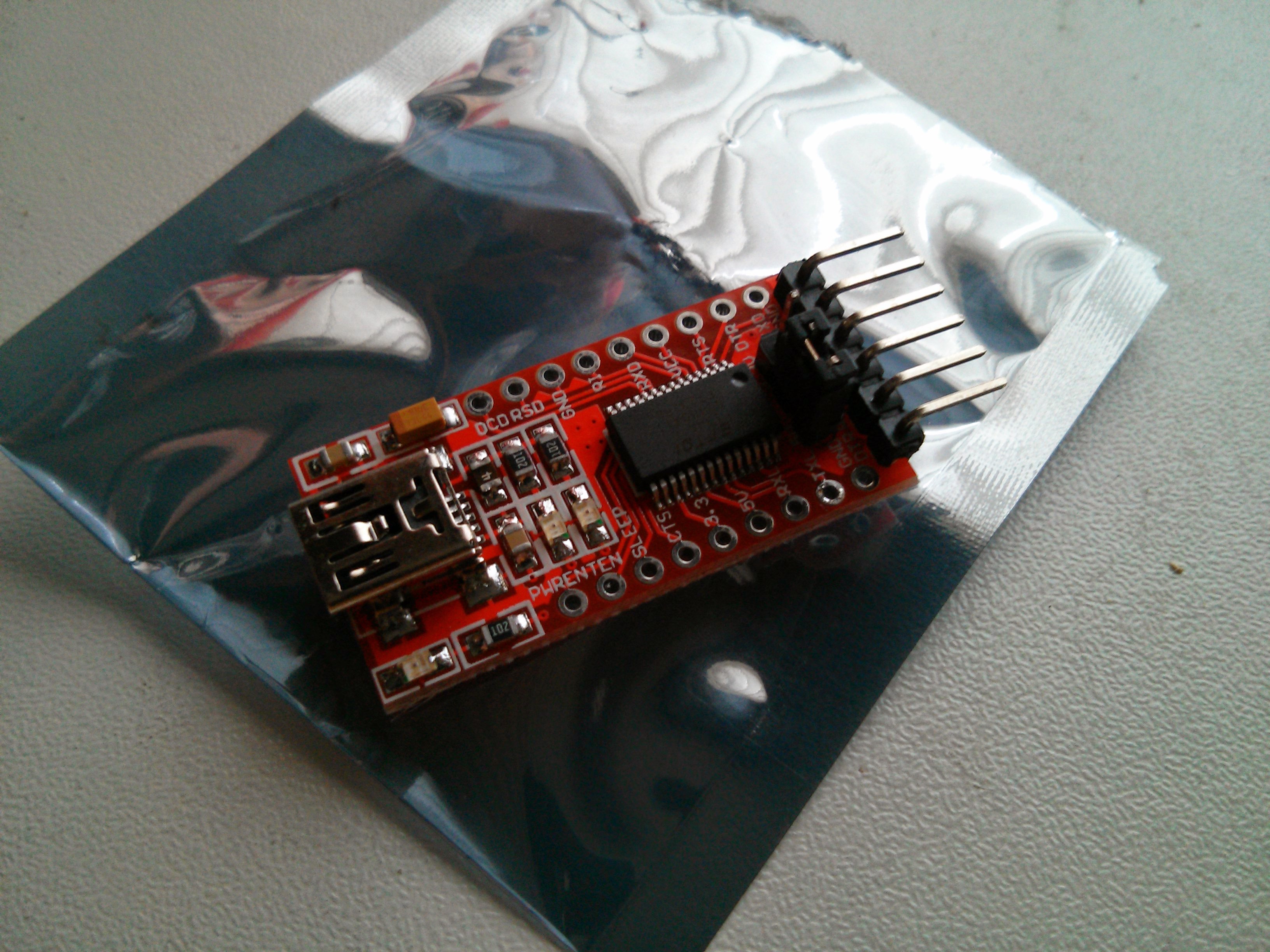
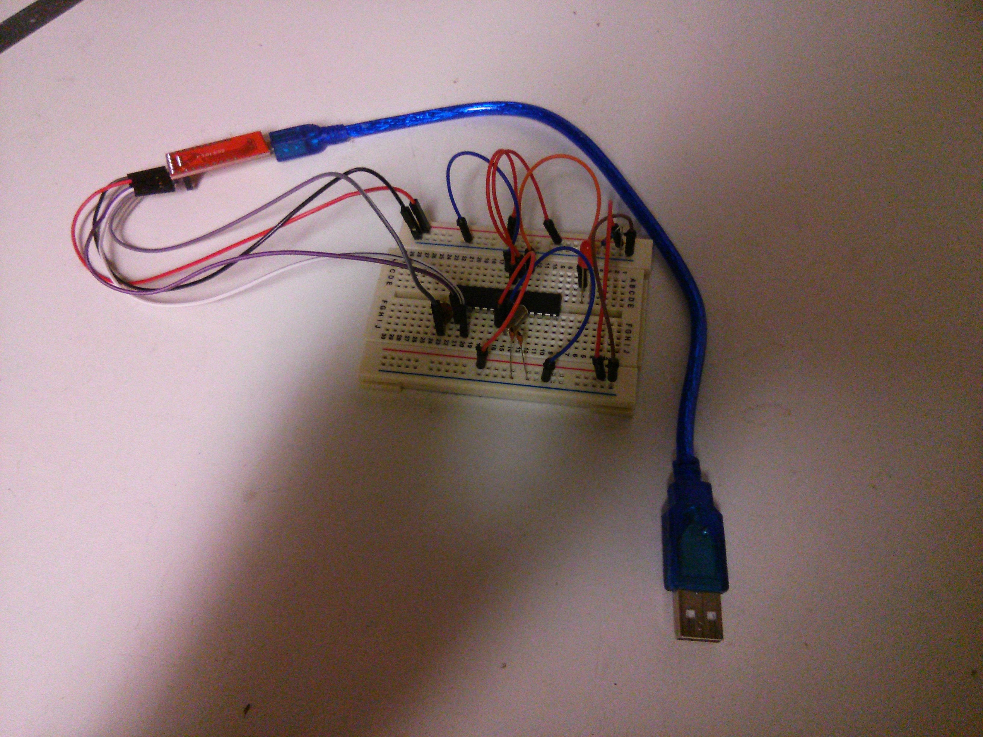
I thought I would start over from the ground level with a atmega328 which is the heart of the arduino and a great chip. To get the atmega328 to talk to the raspberry pi I need a FTDI board which is a USB to serial adaptor board you can get off eBay. I had one annoyance with using this FTDI board which was when ever I uploaded data from the raspberry pi via python serial it reset the atmega328 so after a bit of research I found that if you connected a 120 ohm resistor from pin 1 to VCC it wouldn't reset the chip. The only downside to using a 120 ohm resistor tied to vcc was that you couldn't upload a new sketch to the atmega328 so I added a switch to remedy this.
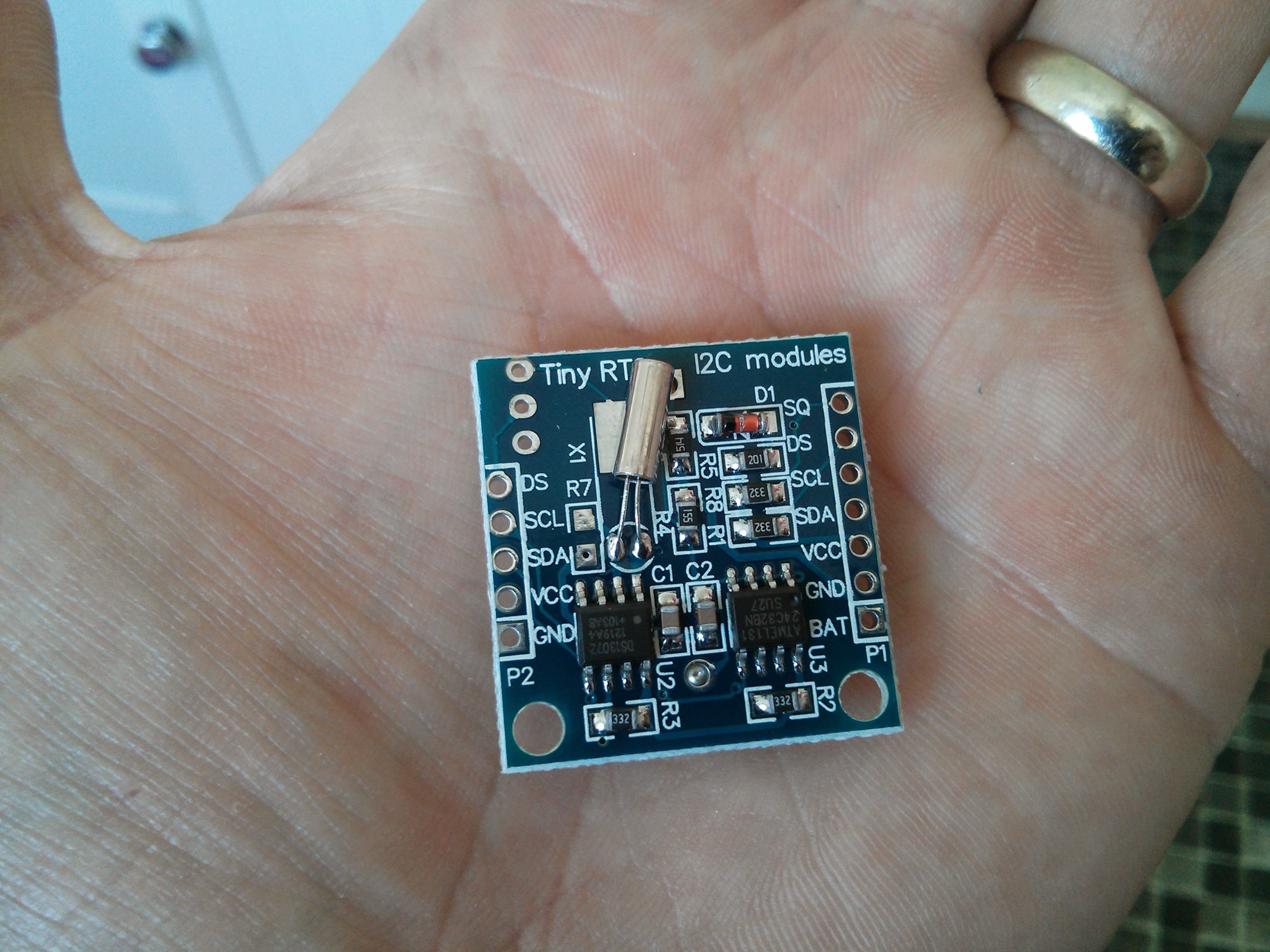
Next up i wanted to add a time function to this project so I picked a DS1307 based breakout board with I2C connection with integrated rechargeable CR2032 cell. This board is great for keeping the time even when the power is off and to count down to a set time or date.
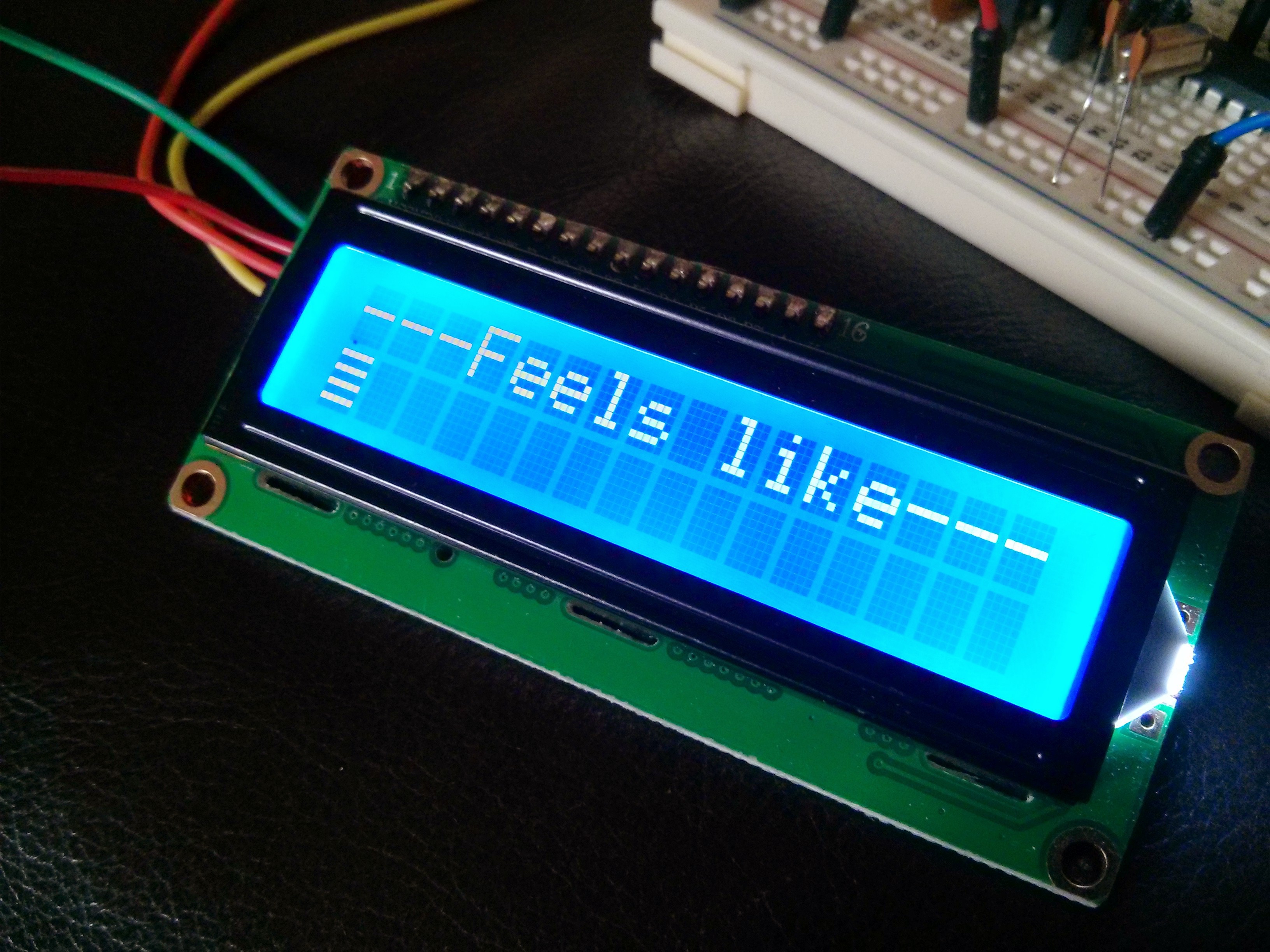
The screen is a 1602 LCD screen with 16x2 character but I found it took up too many pins so i found one with a I2C connections
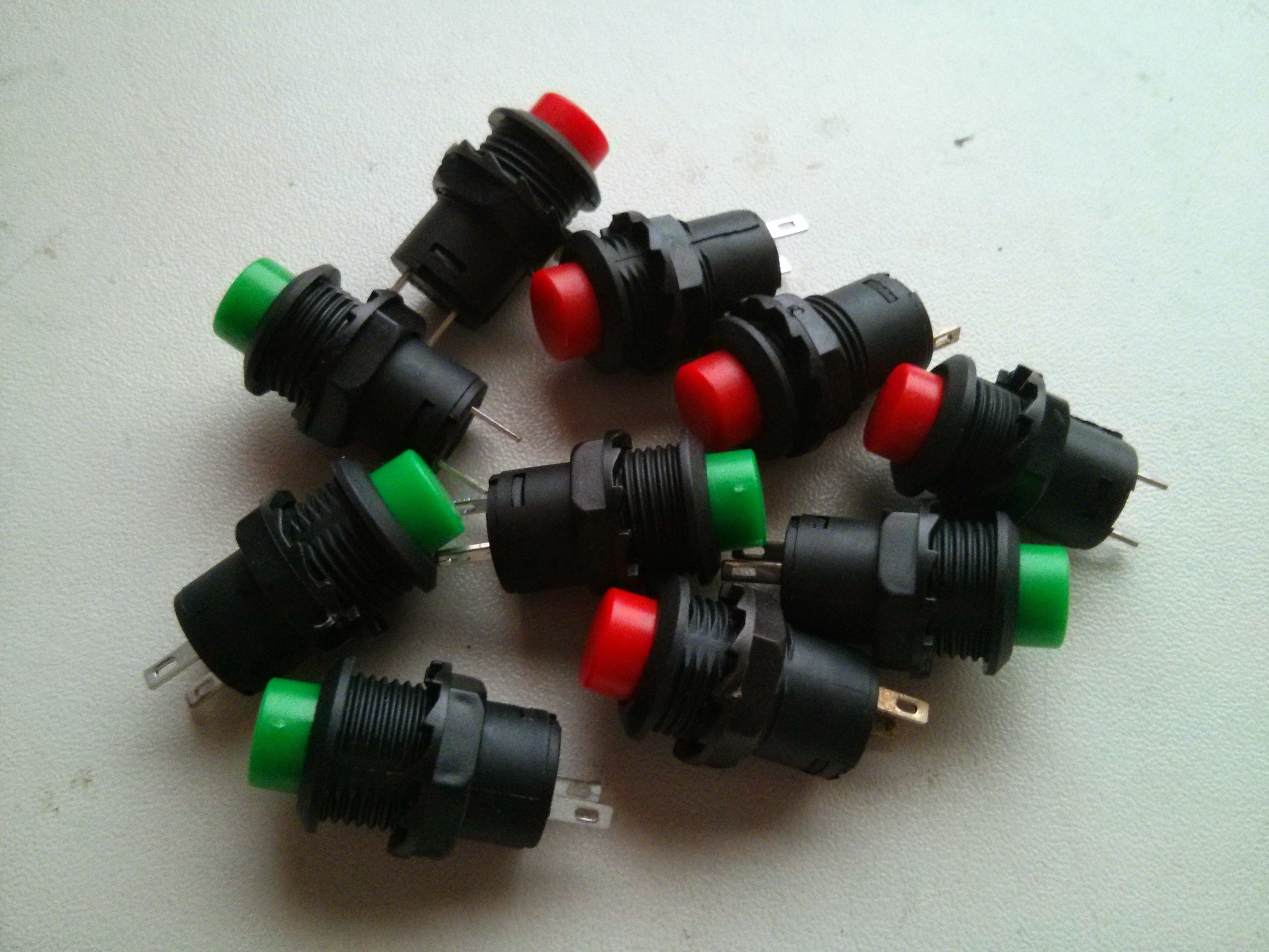
Thought I would add a few button to help furture proof myself for furture updates and added functionality when i need it. Took me awhile to find the perfect button because i wanted them to be quite small but still look good so I setteled on these ones with a 12mm diamitor hole to mount them
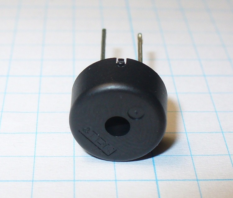
I also added a small piezo speaker to use as a alert or alarm with the clock.
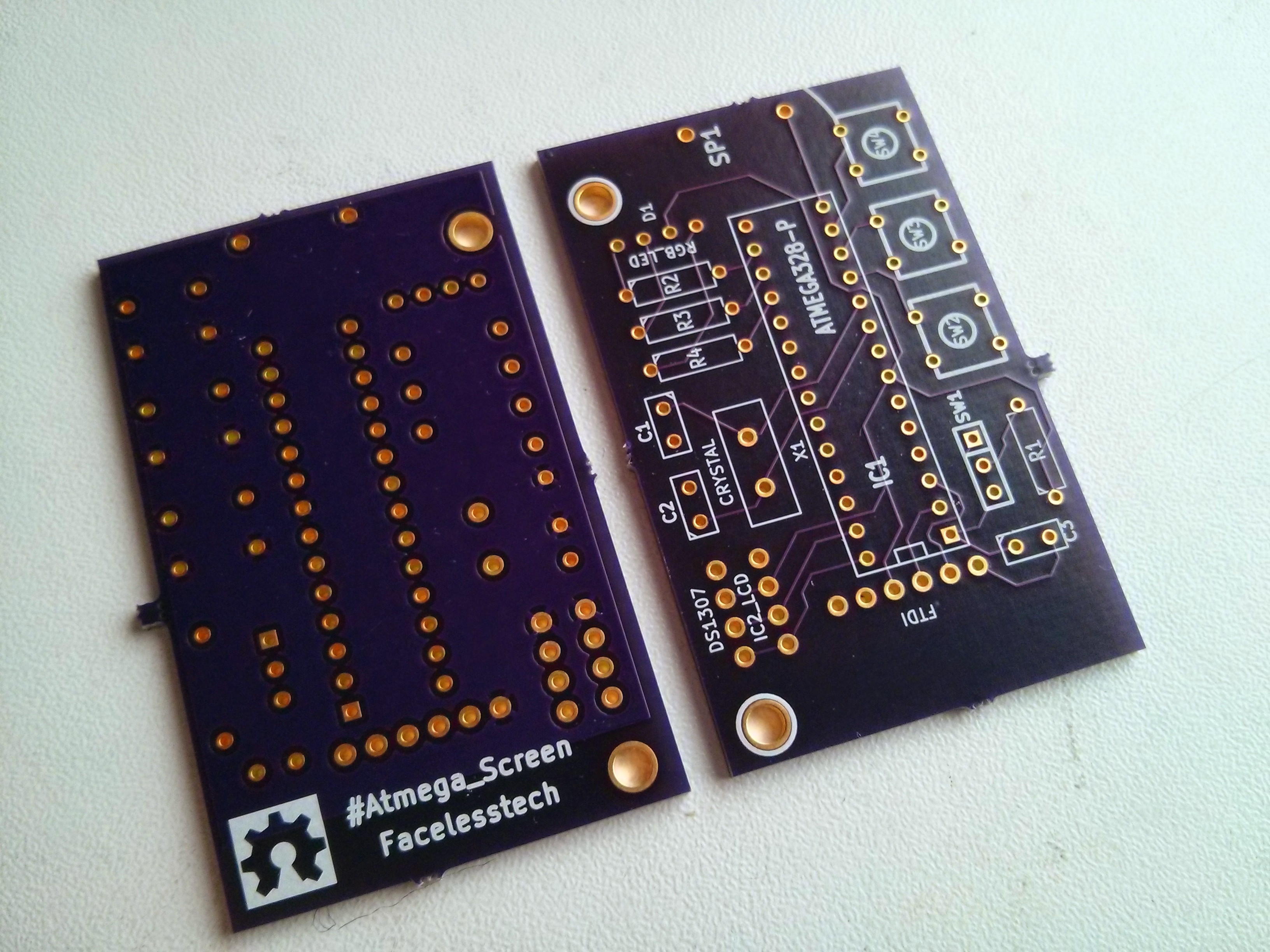
To tie all these things together I design my own PCB and got it spun at oshpark hence the awesome purple PCB. This was my biggest most ambitious PCB I had designed to date
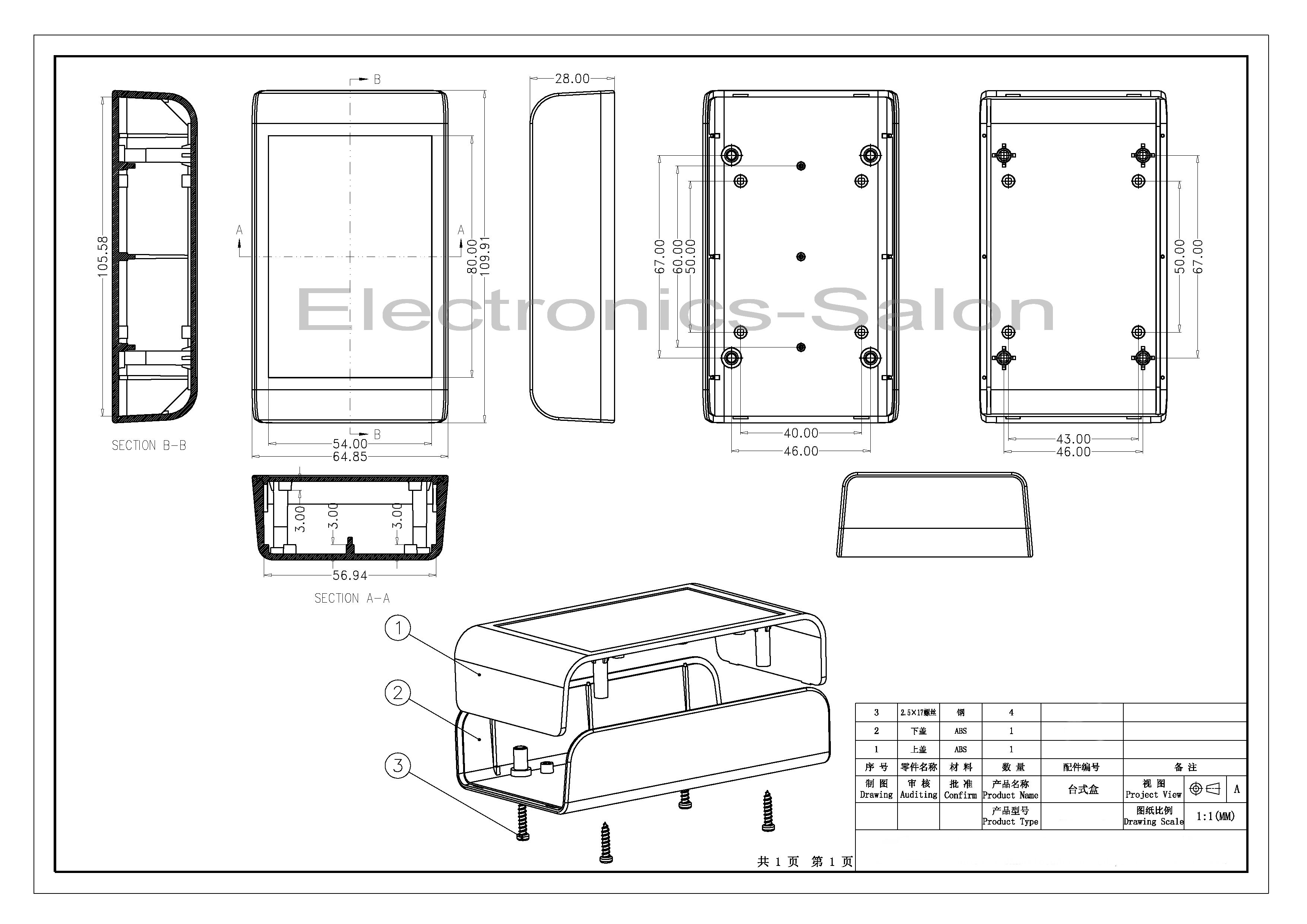
But the thing that made this project the way it is was the enclosure i found on ebay. what set this encloure apart from the rest was the sell provided a very detailed drawing of the enclures with all the dimesions you would need to properly design your PCB to fit. Here is the awesome drawing of the enclosure I used and a link to the full size image
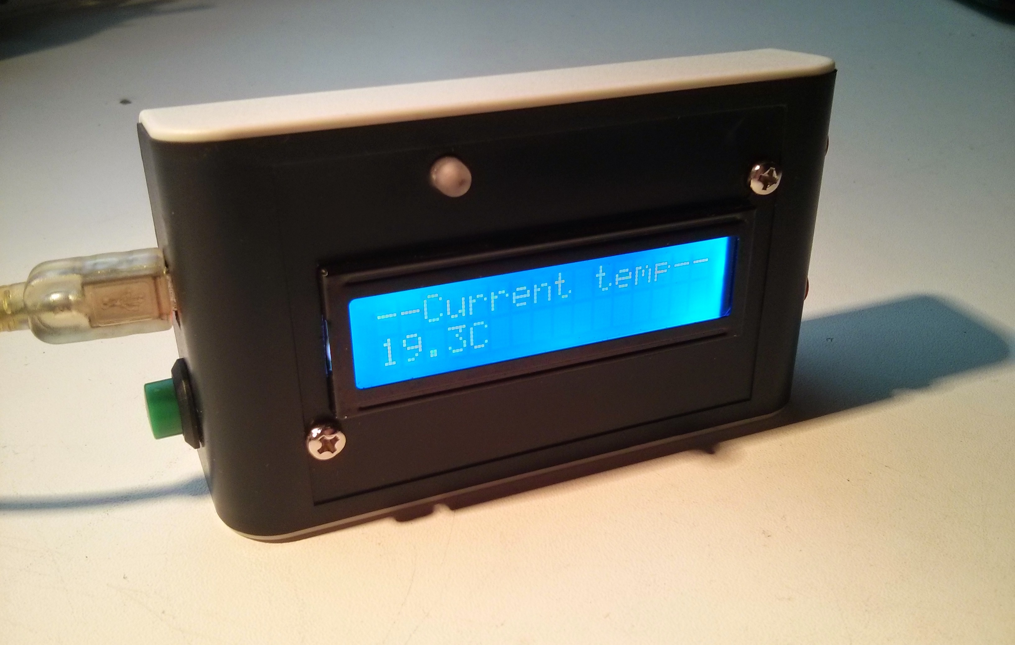
Heres a photo of the finished product. Im really happy the way it came out. 
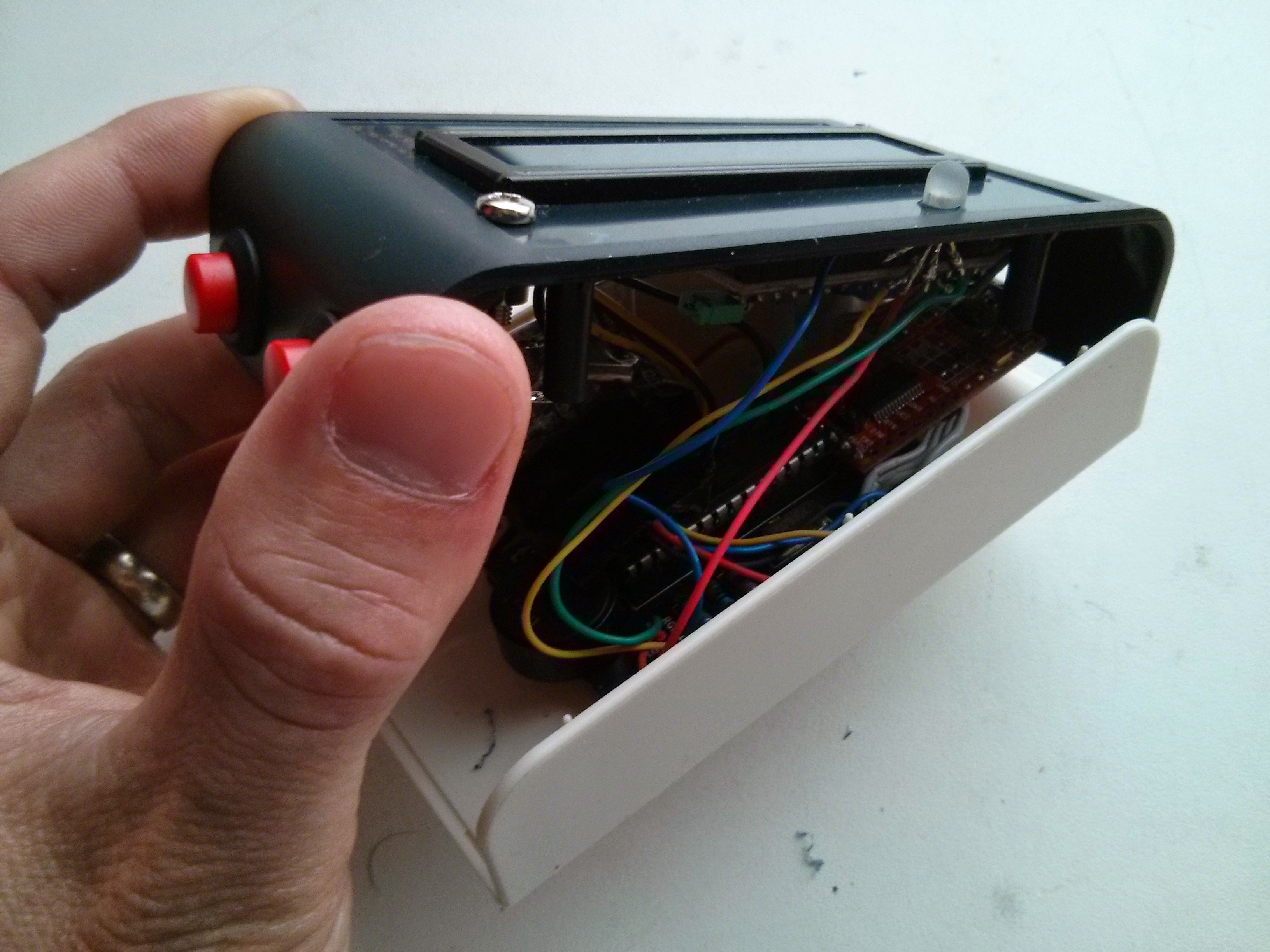
I had a job to cram everything in. Even with a custom PCB its a bit of a rats nest in there. This has to be my tightest packed project to date
Ive made  a quick over view video of the weather sketch running on atmega_screen

Also here is the stock ticker sketch which pulls data from yahoo rest stock api

Here is a basic system diagram of how the #atmega_screen works

###########################################

All software is released under GPL v3 open source licence

###########################################

  • 1 × atmega328 Microprocessors, Microcontrollers, DSPs / ARM, RISC-Based Microcontrollers
  • 1 × 16mhz crystal
  • 2 × 10⁴ 22pf capacitor
  • 1 × 28 DIP socket
  • 1 × FTDI board

View all 15 components

  • All code ported and accounted for

    facelessloser08/19/2014 at 20:57 0 comments

    Finally ported all the code both arduino and python code over to use the new LED I2C screen and uploaded it all to my GITHUB. I found a more affective way to transfuse/encoding the data from the raspberry pi to the atmega_screen. I rapped the necessary data with a #1 or #2 or #3 ect at the start and ; at the end then all the atmega_screen had to do was scan incoming serial data starting #1 and ending in ; ect. This has made it much easier to send the code to the atmega_screen

  • Improved hardware

    facelessloser08/03/2014 at 09:20 0 comments

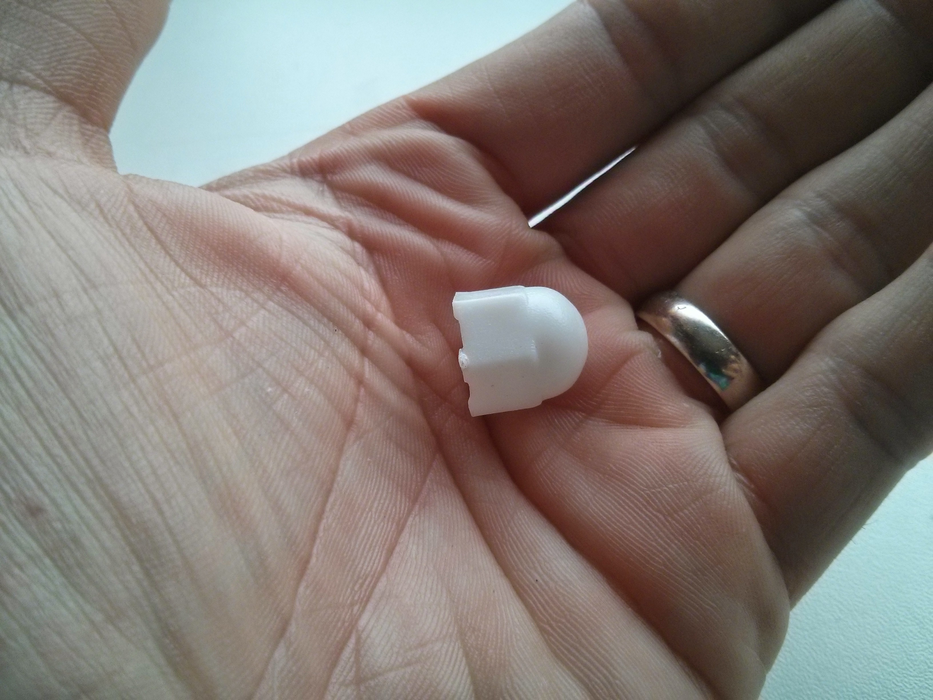
    Ever since I finished the #atmega_screen the RGB LED has bugged me as its far too bright even after I sanded the clear plastic to make it slightly opaque. While I was looking for some nuts and bolts in my random nut and bolt box I found these nut covers.

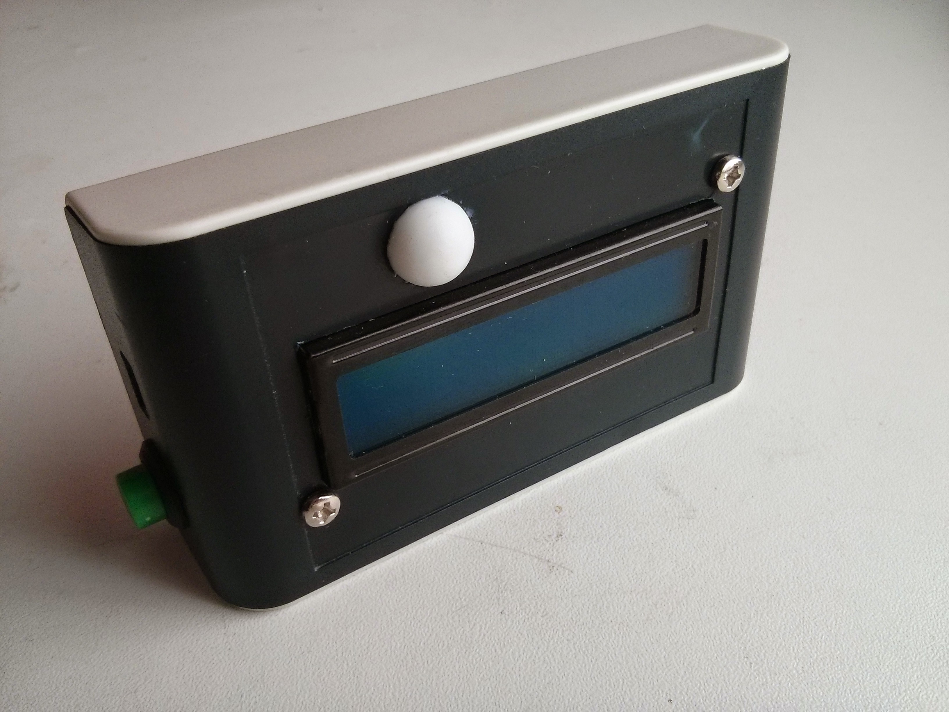
    I cut the dome part off and glued it over the RGB LED on the #atmega_screen. I think it turn out pretty well considering

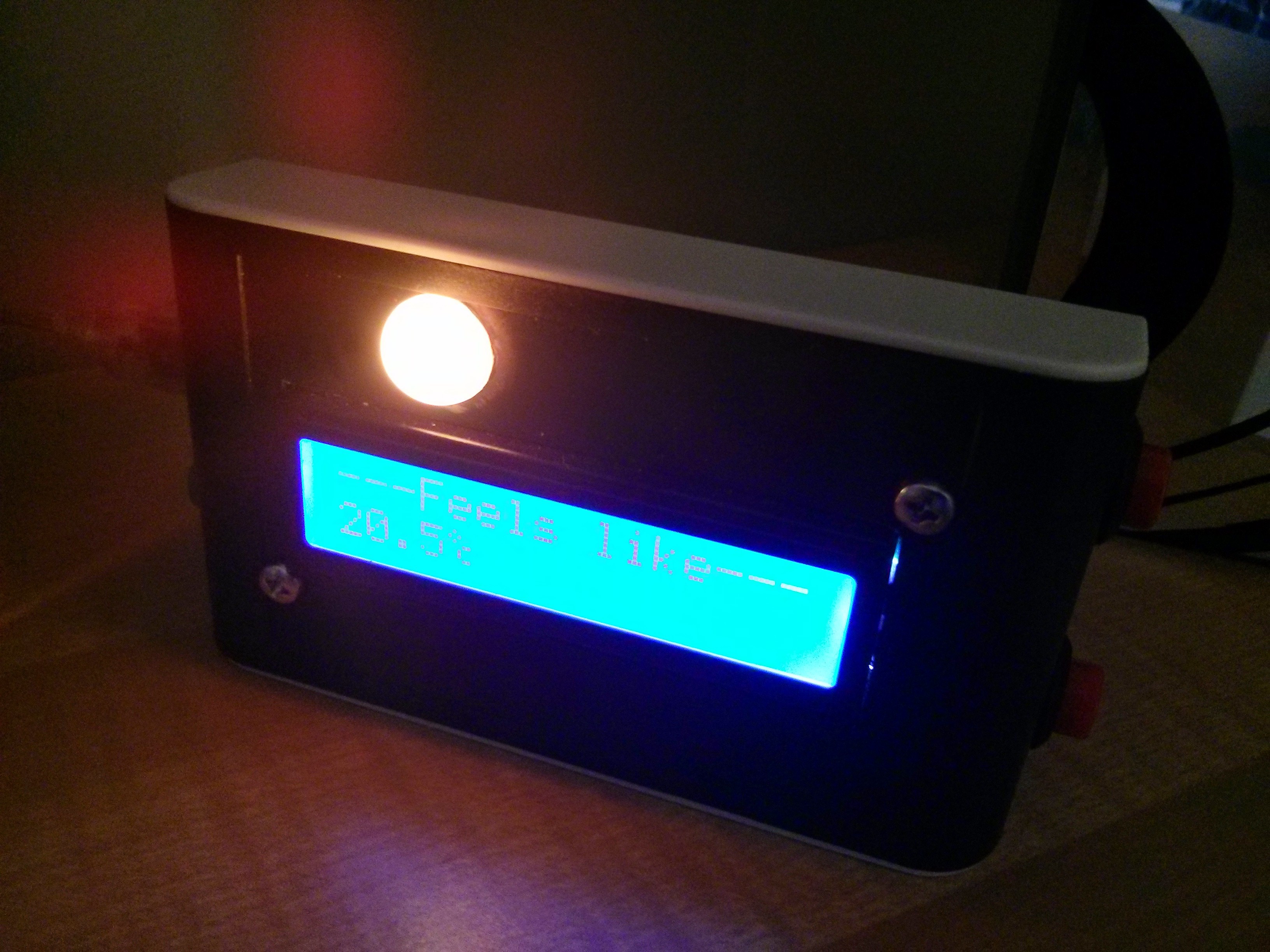
    Here is a shot at it lit up. Its really hard to get a good picture when its lit up

    I added in software the ability to toggle the RGB LED and the screen for when you don't want to glaring at you while watching a film or what not

  • Porting code

    facelessloser07/19/2014 at 08:48 0 comments

    So far I've been hard at work porting my code over to use new screen and added new and exciting features. One feature I've added is the ability to toggle the LCD back light, which is handy at night. 

    I've managed to port the weather, stock, clock and magic 8 ball code found on my GITHUB but I still need to port over the countdown, twitter trending, currency prices and bitcoin prices code.

  • Code code and more code

    facelessloser07/04/2014 at 10:49 0 comments

    Now that ive got the hardware all finished I need to finish up writing the code that runs on my raspberry pi and on the atmega_screen its self. I need to come up with as many different uses for this project I can. So are ive got a weather, stocks, countdown, twitter trending, clock, bitcoin prices, currency prices and a magic 8 ball

View all 4 project logs

  • 1
    Step 1

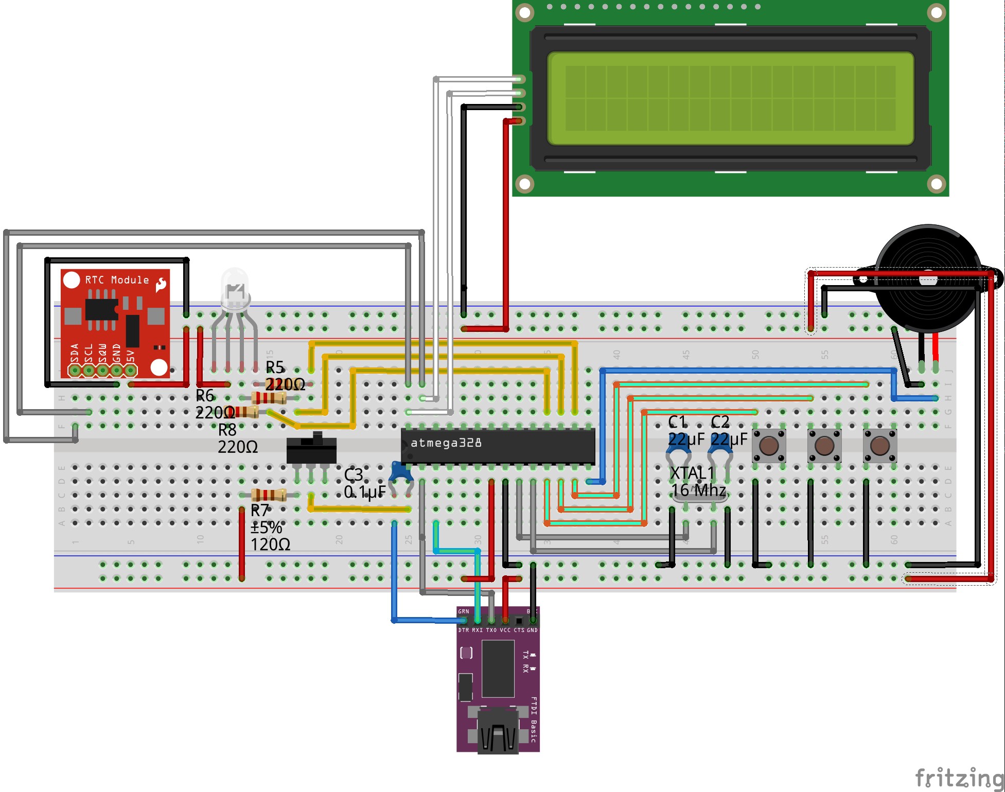
    If you would like to build one of these for yourself here is the breadboard layout

    You will need to burn the arduino bootloader onto the atmega328 so that you can upload the sketch from my github HERE. You are free to use what you want from this so if you don't want the speaker or as many buttons just change the circut to suit.

  • 2
    Step 2

    If you would like to make my project as it is you can order the PCB off of oshpark HERE the PCB is $17, All the gerbers and design files can be found on my github HERE too. The enclosure can be order off ebay HERE (not sure how long this link will last tho)

  • 3
    Step 3

    Then all you need to do is populate the board and cram it all into the enclosure after cutting the nessasery holes out

View all 3 instructions

Enjoy this project?

Share

Discussions

Craig Hissett wrote 10/15/2016 at 11:21 point
I love this mate! Very useful! Have you tried running the python script on windows/Mac? This would be great sat alongside a desktop at work :-)

  Are you sure? yes | no

facelessloser wrote 10/15/2016 at 11:35 point

Thanks, it's an old project I'm sure it would be possible to use it on a windows with schedule tasks but not to sure how you would run it in the background on Mac.

  Are you sure? yes | no

Depot wrote 08/10/2014 at 19:22 point
This could be smaller and look better with a small OLED display IMHO. Check them out, there are some different sizes on Adafruit. Mine looked great.

http://www.adafruit.com/products/661

  Are you sure? yes | no

facelessloser wrote 08/10/2014 at 19:30 point
Thanks, I have been looking at these screens to use in a different project. Have you used them before, are they easy to write things to the screen. Really hate the way the LCD screen I used does it

  Are you sure? yes | no

Depot wrote 08/10/2014 at 20:06 point
I don't see a reply button below your reply, so I guess I reply to the thread?

One issue I had was that my Arduino Nano have too little RAM (ATMega 168) to buffer the screen properly with the Adafruit code. At the moment I'm only dumping static screens into the thing. I expect the text to work nicely with a new microcontroller. I didn't have any problems with the SPI communication. The places where it might go wrong are most likely the pin connections or starting up the charge pump or my low RAM.

  Are you sure? yes | no

Jasmine Brackett wrote 07/21/2014 at 22:21 point
Jasmine wrote a few seconds ago
Hello facelessloser, thanks for entering The Hackaday Prize and sharing all the pertinent files. It looks like you are off to a great start.

We recently extended the deadline for this round and updated the rules, so if you haven't checked the requirements recently, I'd urge you take another look http://hackaday.io/prize/rules-en (search for "4.HOW TO ENTER").

I'd suggest filling out your profile a bit more, and making sure you put a link to your submission video in the links section of this project. Don't forget to tag your video on youtube with the keywords TheHackadayPrize and quarterfinals, plus put a link back to your project from the description on youtube.

Good luck!

  Are you sure? yes | no

facelessloser wrote 07/22/2014 at 06:58 point
Thanks for the feedback. I'm planing on adding more to my profile and adding the link to my video and back again.

  Are you sure? yes | no

Similar Projects

Does this project spark your interest?

Become a member to follow this project and never miss any updates