Dominik Meffert
-
Moving vacuum related stuff to a new project
03/31/2021 at 13:31 • 0 commentsTo keep everything organized I moved everything vacuum related to a new project and kept everything from the arc welder circuit at this project.
If you are interested in how it goes on with the vacuum project, you can find it here:
Fighting Oxidation with Vacuum | Hackaday.io
If you are interested in the arc welder circuit + optically controlled plotter circuit you can have a look at this project.
-
Heat resistant Electrode Holder
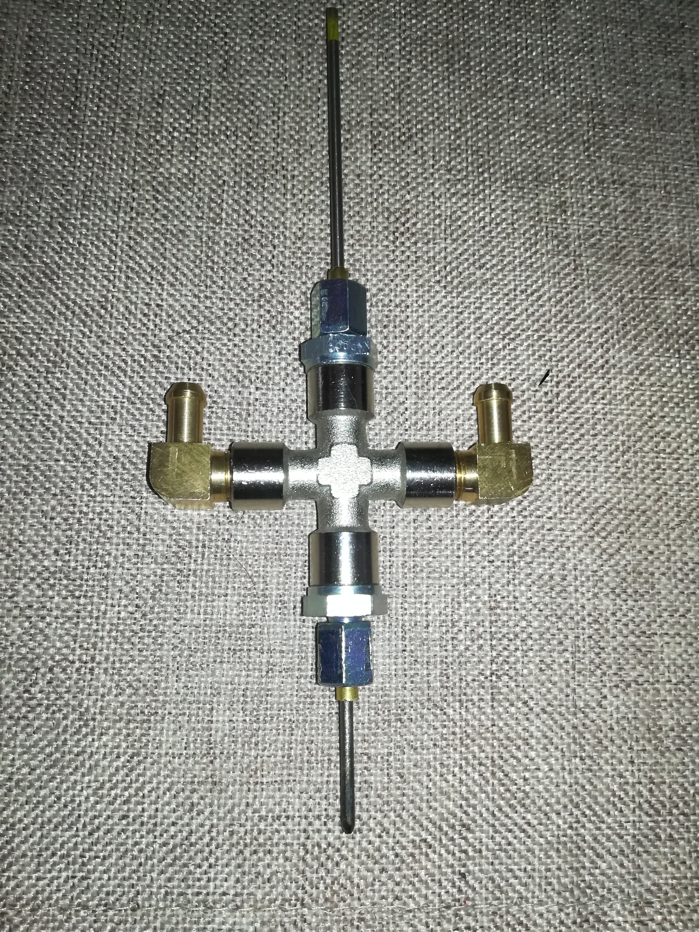
10/29/2020 at 16:11 • 0 commentsFor further testing a heat resistant electrode holder is needed which can handle the temperature of multiple hundreds degrees while staying cold enough to be mounted on 3D printed parts.
![]()
So here is my attempt of building one.
It's made off a cross fitting, hose connectors, hydraulic fittings and a brass tube, what keeps the electrode holder water thight while offering space for the tungsten electrode.
The plan is to keep it cold by a constant water flow through it. Maybe by using some thermal paste it could also keep the electrode a bit cooler. The electrode is loose inserted into the brass tube. There should be around 0.3mm of space between electrode and the inner wall of the tube.
The electrode could be fixed by a clamp at the upper and lower end of the brass tube.
![]()
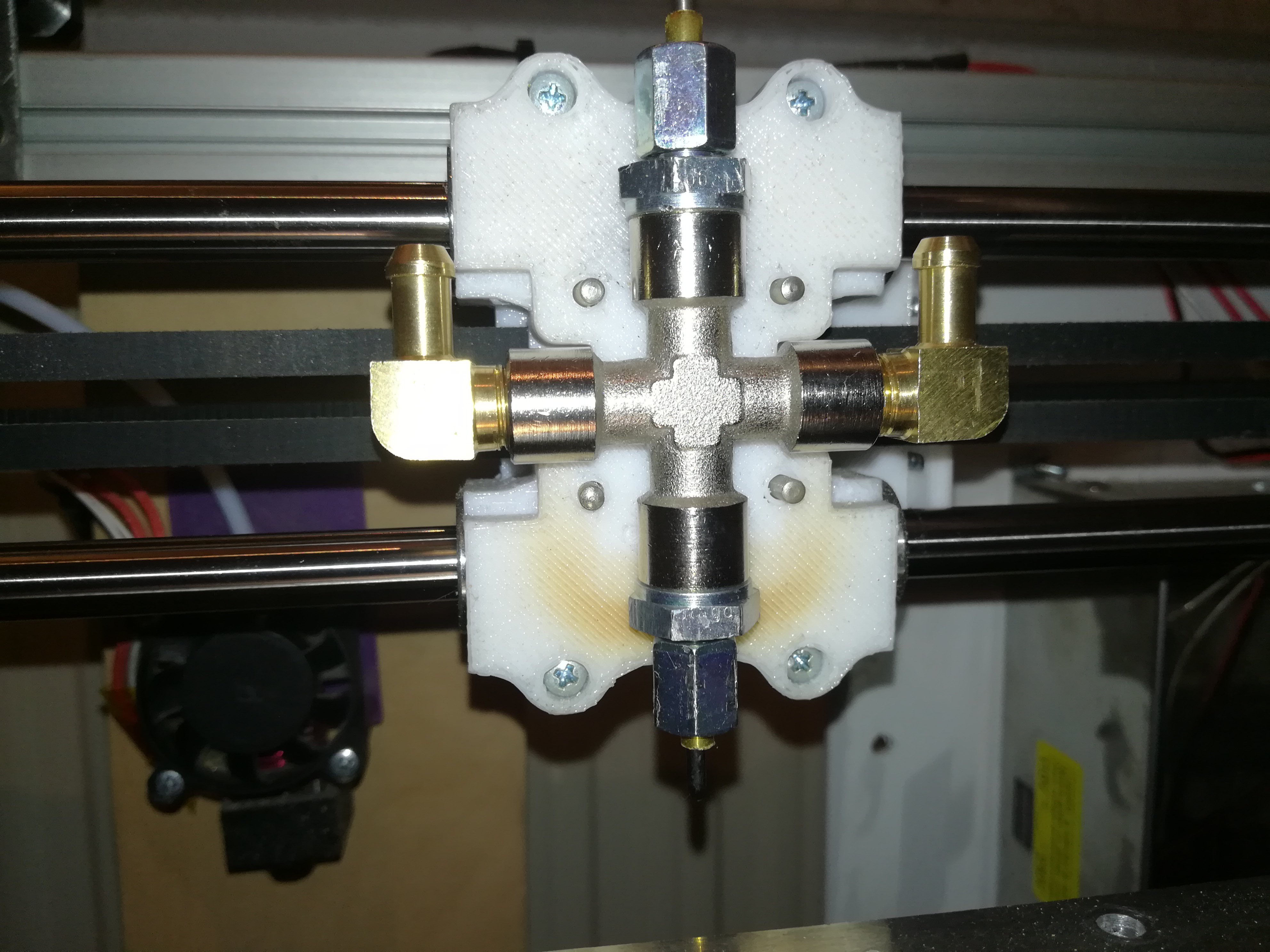
The X Carriage for scale. All parts are 1/8" BSP size. Only a 3D printed mounting bracket and a hose connection is missing.
-
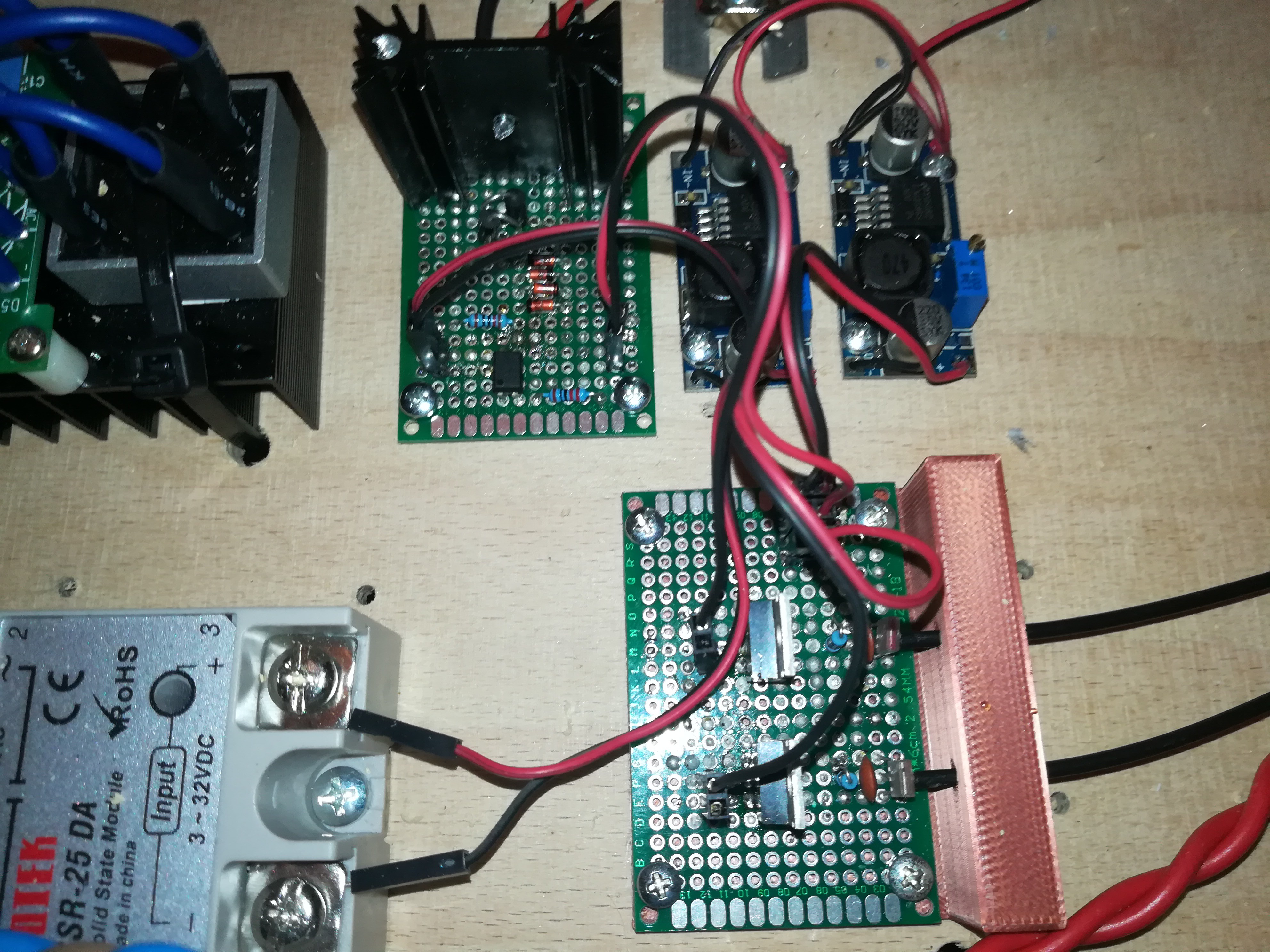
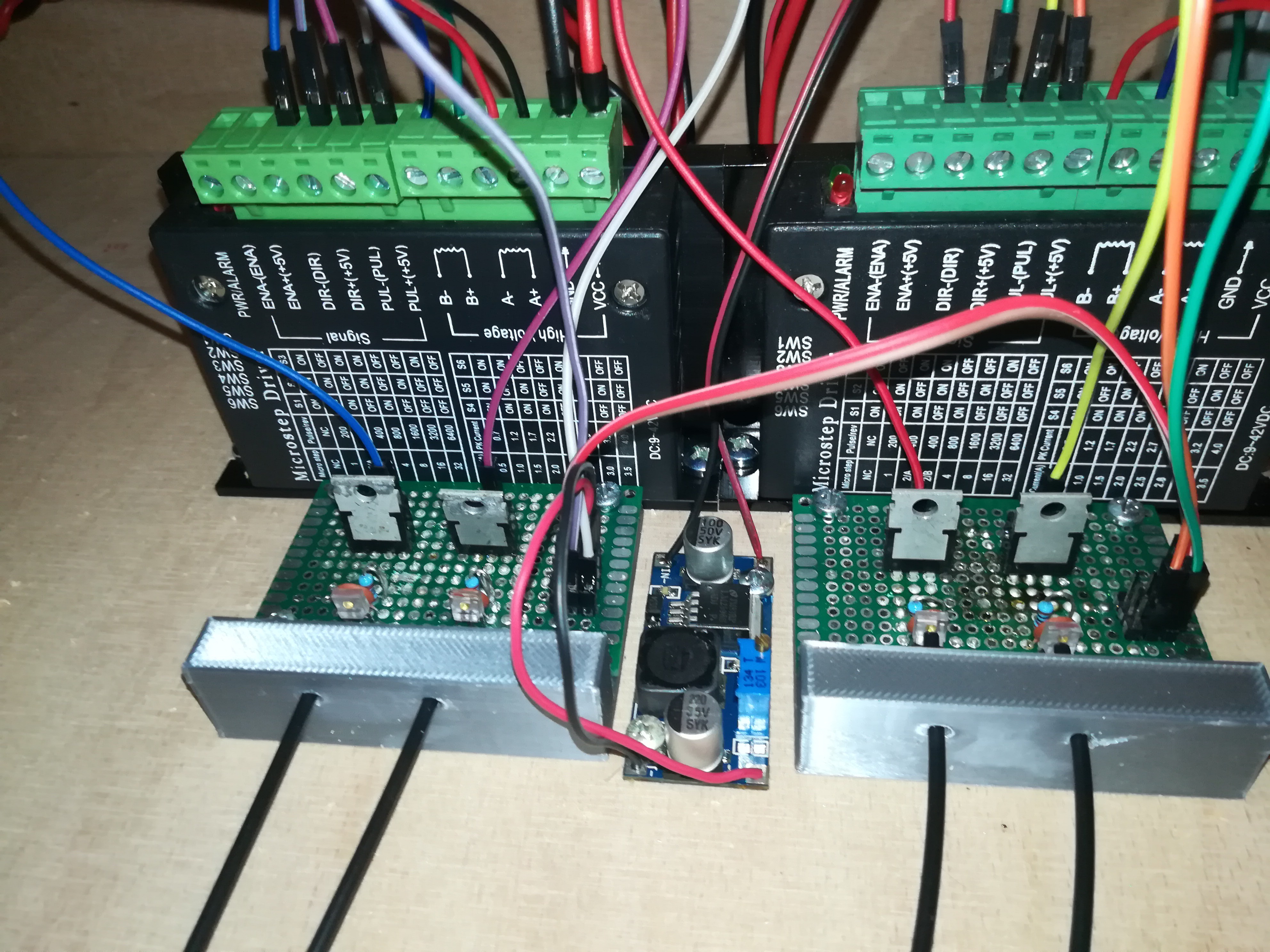
DC Side Switching
10/23/2020 at 03:17 • 0 comments![]()
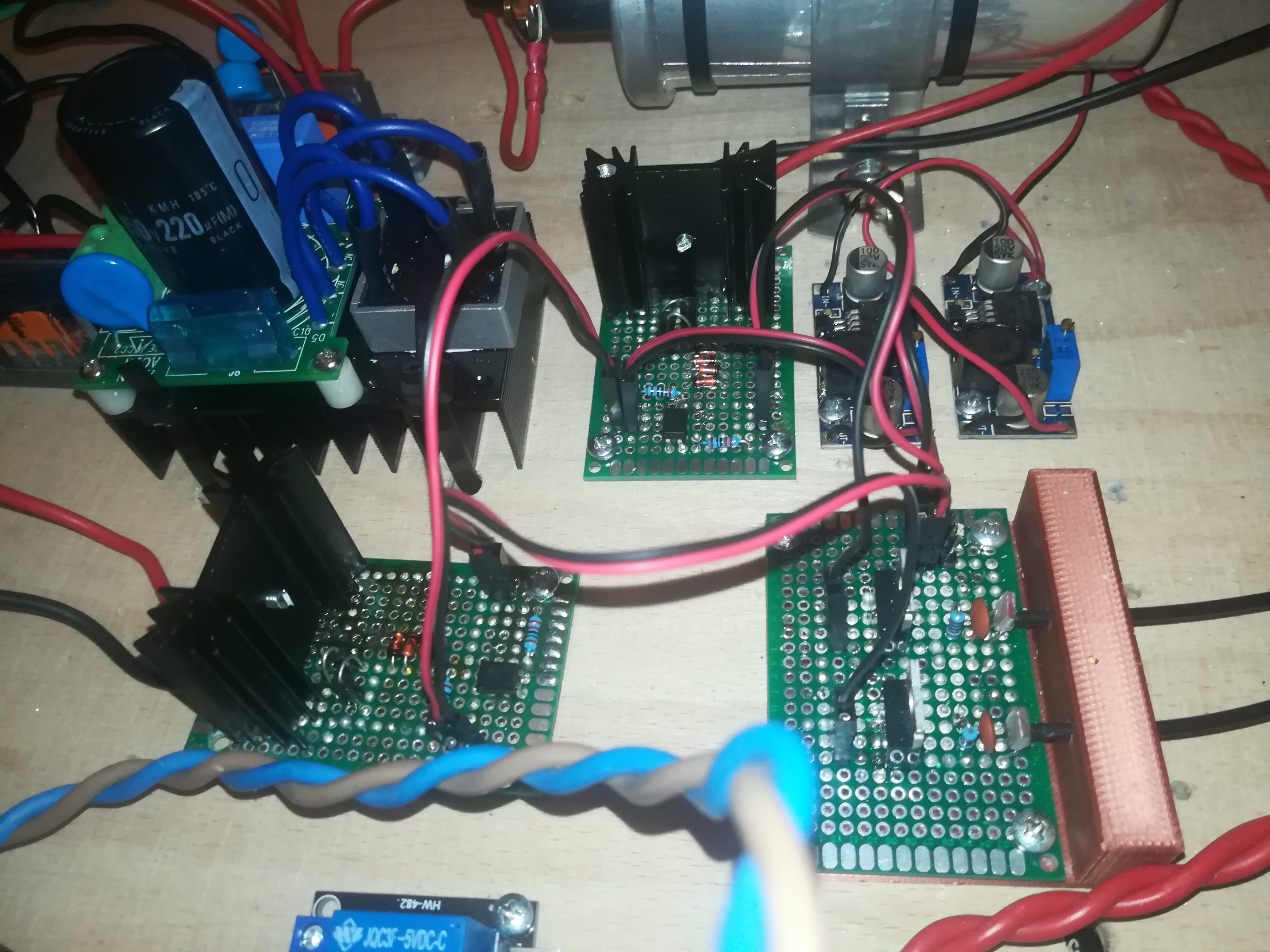
I've built another MOSFET board for switching of the DC side to make very fast switching of the power source possible.
I tested it out and realized that the too long ON-times which I thought were caused by the rectifiers capacitor were still there and therefore were caused by the GCODE.
So better GCODE is needed.
I ordered some fittings, which I want to use for building a watercooled electrode mounting bracket. They should arrive by the middle of the next week.
-
Testing everything together
10/18/2020 at 03:13 • 0 commentsNow that the arc starter, arc power, stepper driver and printer controller work it is time to test everything together.
In this test I tried continuous mode for melting the powder. The result looked good but was only partially melted solid. By trying out a lower moving speed the result got not really better but the tungten electrode melted due to the heat and no cooling. The 3D printed mounting bracket also melted, what was ok, because it was not designed to withstand high temperatures. I think I will design a watercooled all-metal toolhead in the future which can handle the temperature and prevent the electrode from melting.
I did another test and this time I tried to print a dot matrix with the idea that multiple dots placed close to each other can create a solid structure, which was the case.
I think with this method the amount of heat/energy can be controlled more precisely than with continuous mode:
I could be wrong, but I think with continuous mode there would be only the power (Amps/Voltage Setting) and the moving speed adjustable and with dot matrix mode there would be also the exposure time and space between dots adjustable, what I think could lead to a more precise and reproducable heating. I think it would also be possible to add short cooling time between the dots to prevent the heat from the pulses from adding up on each other what could prevent overheating of the electrode and spreading of the heat in the powder. Maybe doing so could also reduce the width of the printed lines, what would lead to more pecision.
![]()
First printed single layer object - there is plenty room for improvements :)
I think a thing that has gone wrong in this test was that the switching of the welding power has been slower than the actual setting. The cause for that is, that I'm currently switching the AC side with a SSR before the rectifier and its capacitor which has to charge and discharge, what I think is slowing down the switching time.
I did that because the SSR was the only semiconductor part which not got destroyed from the arc starter.
I replaced the continuous arc starter with a single pulse arc starter a while back and did not try another MOSFET out. Maybe it would work with the new arc starter and I will test it out in the next few days.
Fried MOSFETS were a huge problem in the construction of this project.
The first time I got the new arc starter to work the MOSFET got fried after some time, I assume from ESD on the gate.
![]()
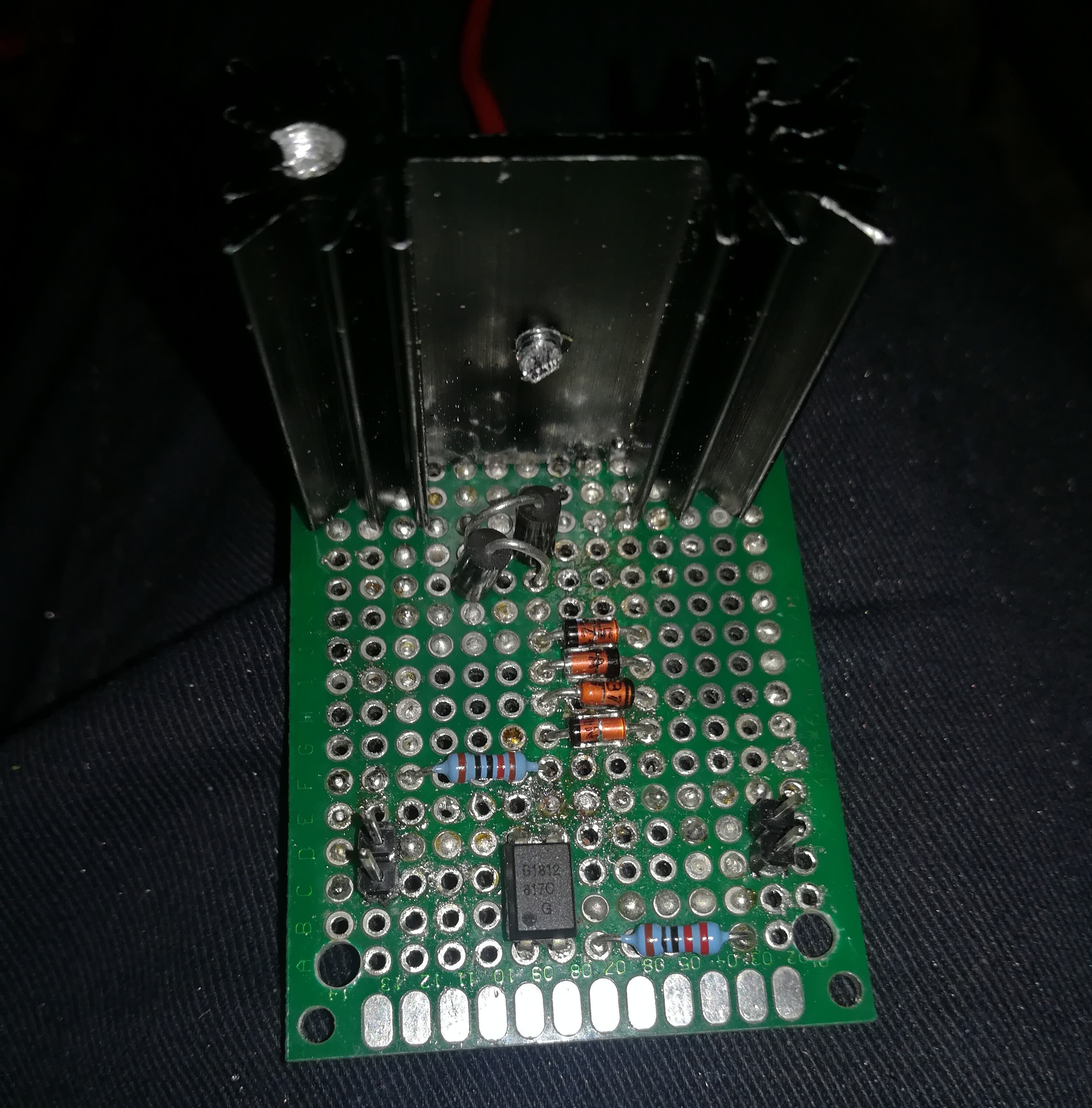
I designed a new pcb with four 7.5V zener diodes between gate and source to clamp the voltage to 15V and two 265V TVS diodes between drain and source to clamp the voltage to 265V. The MOSFET is a IRFP460 driven with 12V.
This MOSFET board switches the arc starter and maybe such a board would also work for the arc power.
I hope this design will last long, because I have no idea what else I could do to prevent the MOSFET from dieing.
-
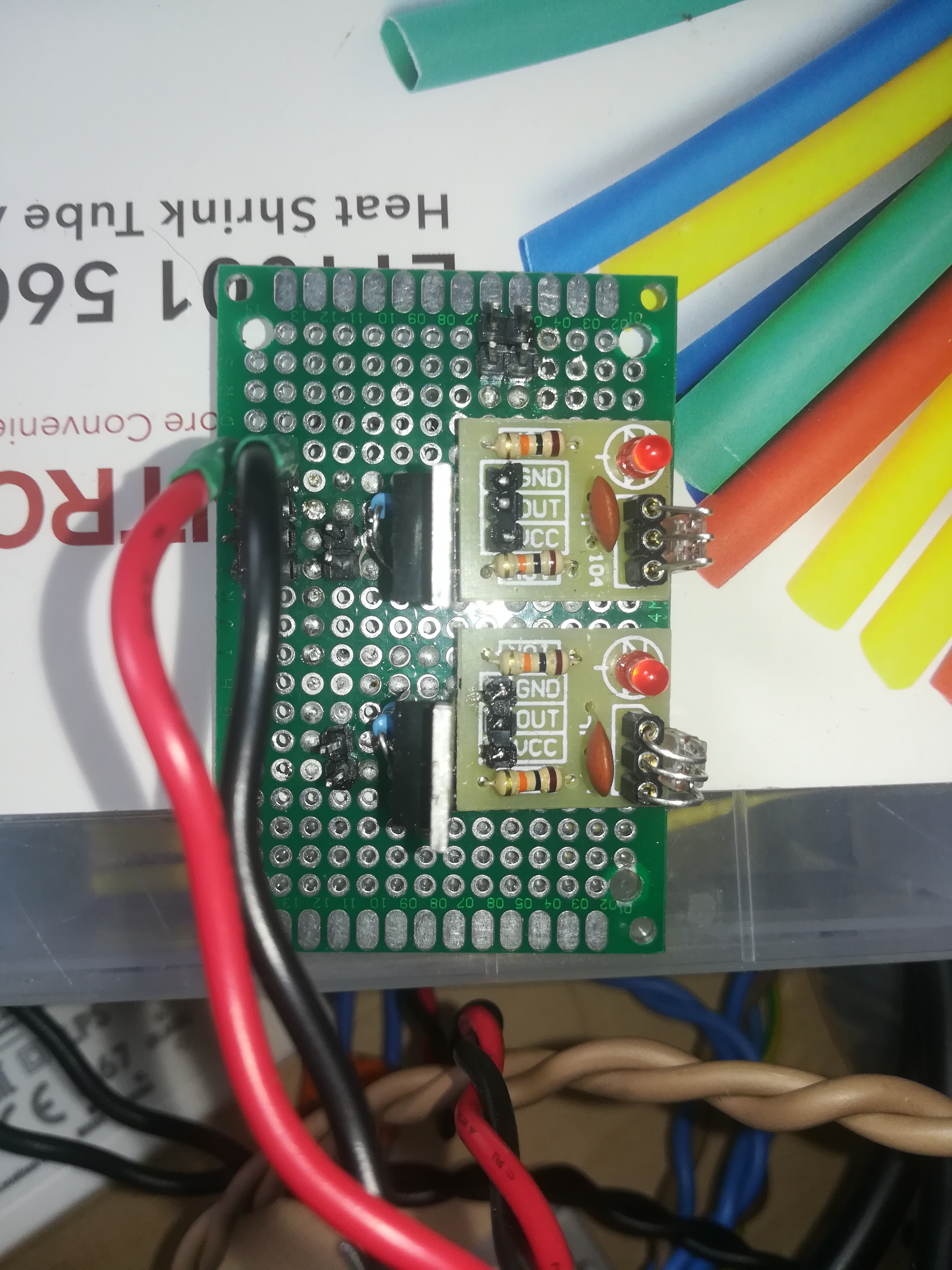
6 Channel Optical Controller
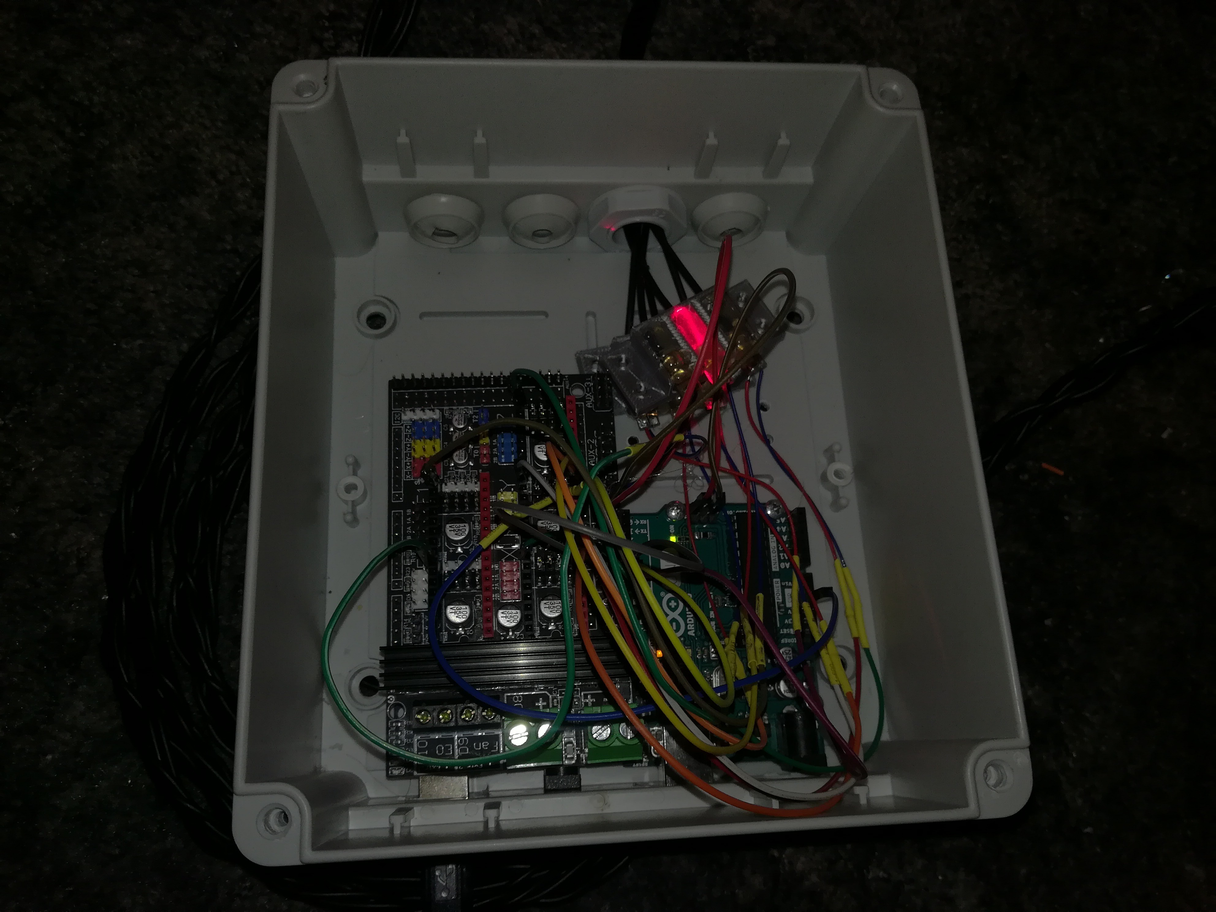
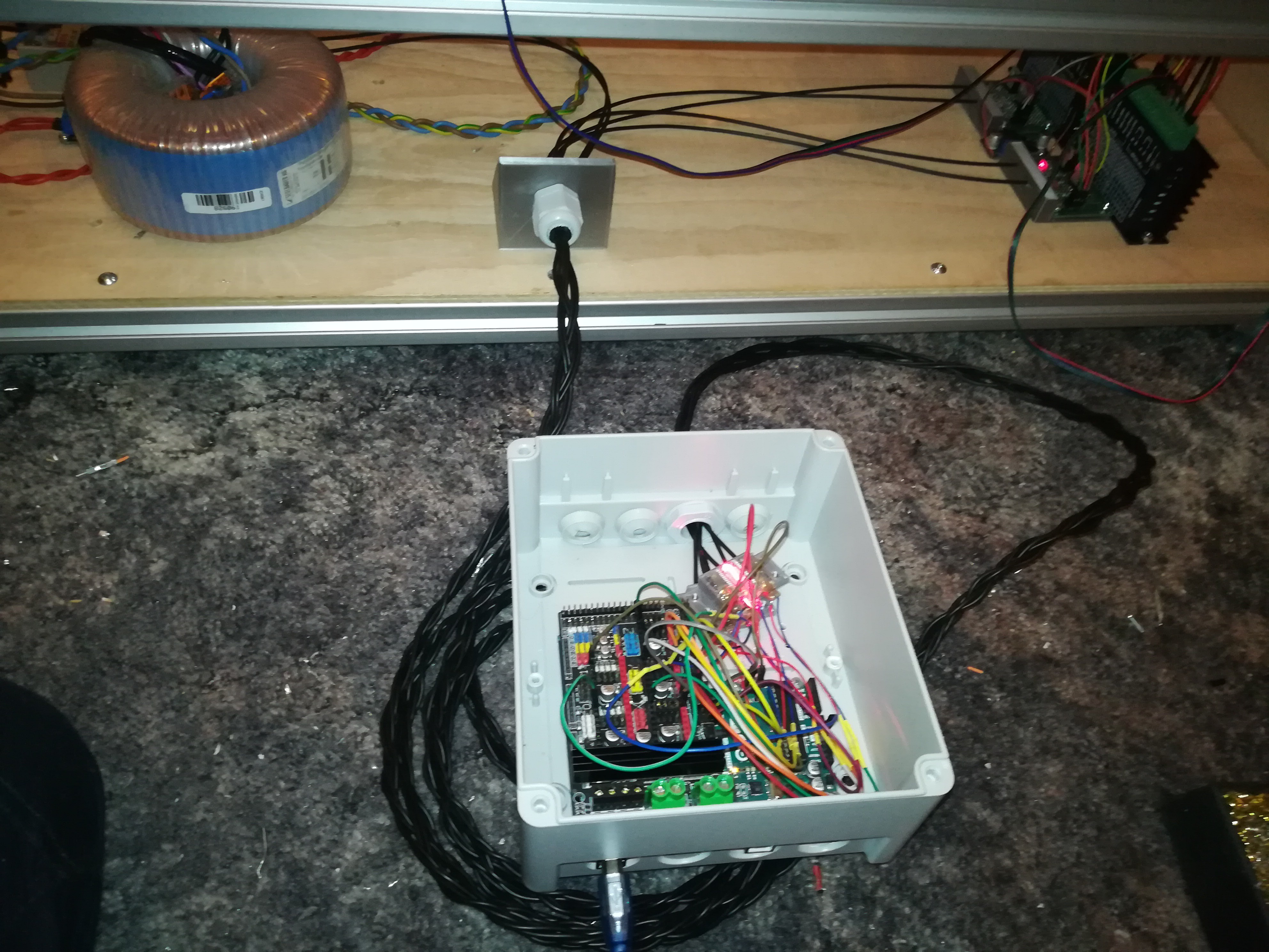
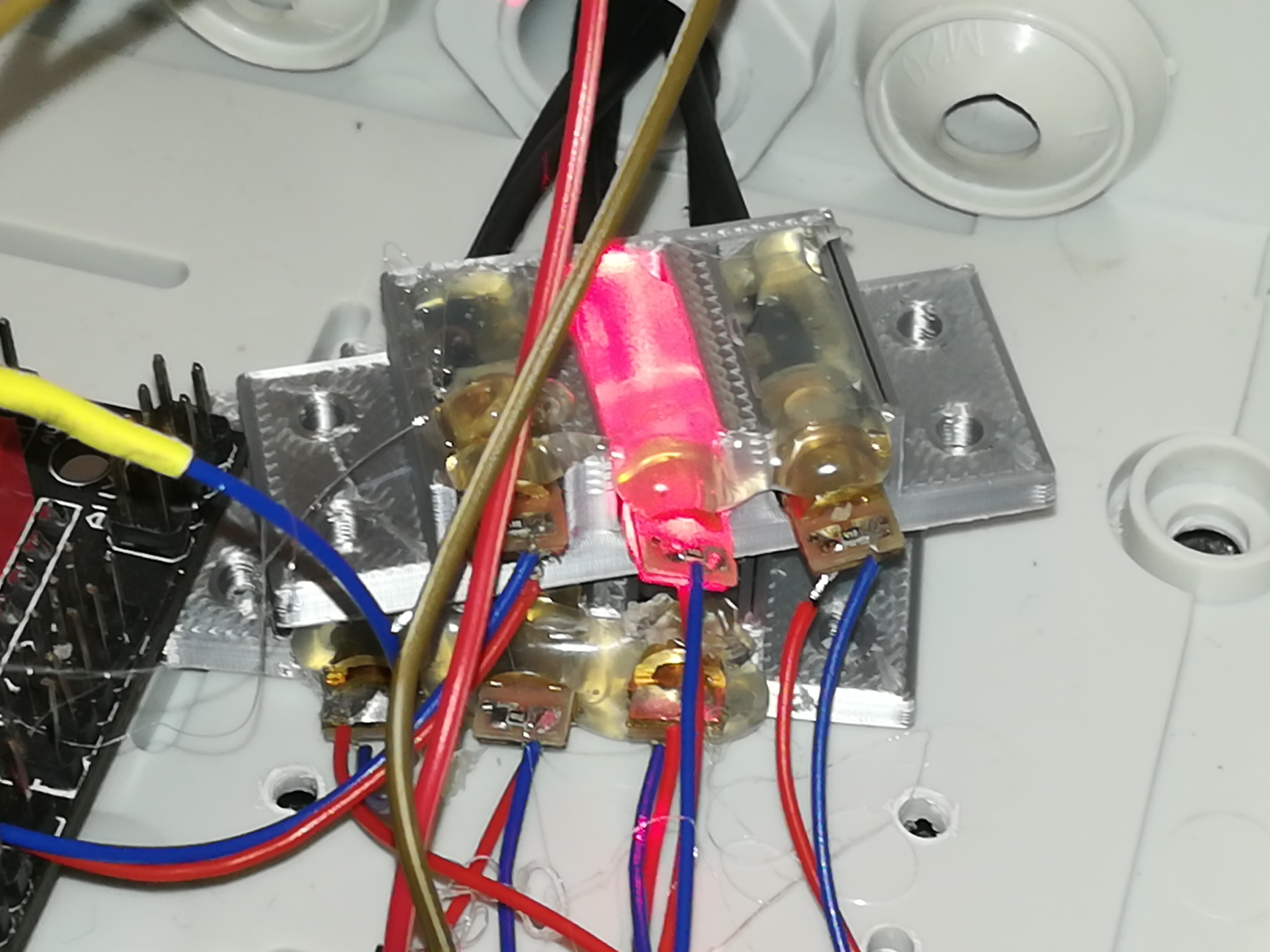
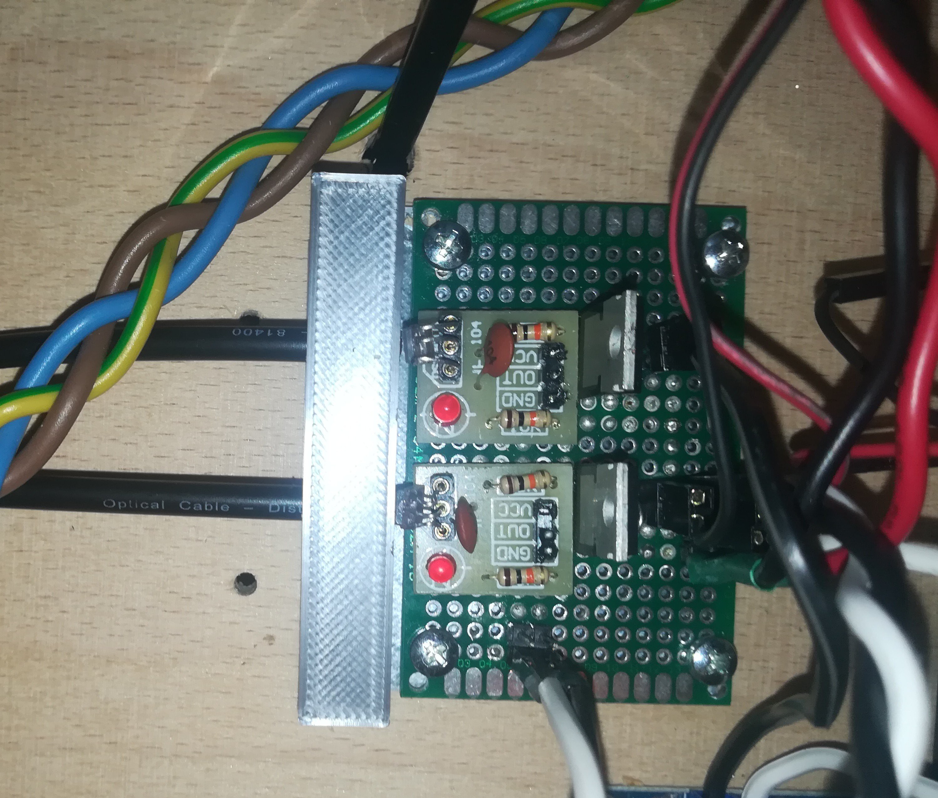
10/18/2020 at 00:03 • 0 commentsTo get the machine operational I needed at least 6 optical channels for controlling it from a for the controller and the notebook noise-safe distance. Step and Dir channels for two stepper drivers and signals to turn on the arc starter and arc power.
![]()
![]()
![]()
![]()
![]()
The system works very reliable and with the new single pulse arc starter the motors are no longer noticable affected by the arc starter, even though my TV turns still on and my notebooks screen output crashes when it is too close to the arc. The optical cable is a cheap 25m toslink one that I cut in six 4m pieces to have enough room between the notebook and the printer (about 2m). The controller which is an Arduino Mega + Ramps 6 plus is connected to the lasers which are hotglued in 3D printed brackets which also hold the fiber cables. At the other end are also 3D printed brackets with no-name "ISO203" unmodulated laser receiver modules. I soldered the parts from the module (sensor, capacitor, resistor) to a pcb to prevent the sensor from false readings which it has sometimes due to vibrations when placed in the original mounting slot.
-
Pulse Welding
10/07/2020 at 00:14 • 0 commentsI always wanted to operate the machine in pulsed mode, to focus the heat on a small spot without spreading it to much in the powder, but I did not know how to do it until I recently figured it out. I saw a video by Electroboom (https://youtu.be//CkGVMWK10qU) in which he builds a taser from a car ignition coil and this circuit was exactly what I needed for a new arc power source. For controlling the pulses I'm using a MOSFET connected to a optical receiver controlled by a microcontroller instead of the continuous HF starter that I used before. By doing so it was also possible to simplify the design and to reduce the noise a bit.
![]()
I tried out another transformer with a higher output voltage, because with 60VAC output/86VDC rectified I could not get a stable arc which would be needed for testing out longer exposure times.
I tried out more current and at this setting it seems to be enough for melting the powder - even with a very short pulse (not shown in the video). It maybe could also be used for engraving metal in pulsed mode to prevent heat deformation. So I think the next thing could be getting the stepper motors and printer controller to work for testing out melting pattern into the powder and drawing/engraving something on metal. If the current setting will turn out to be still to less powerful I could double power from 600W to 1200W with a more powerful transformer + power resistor combination. I also looked into using an inverter based power source, but I think that will make the machine to complicated to rebuild and so I will likely stay with the current transformer + resistor design. I think if adjustable current settings would be needed, I could add some power resistors for defining the upper current limit and add switchable resistors for further reducing the current if needed. But maybe changing the pulse time would be enough for heat regulation.
-
All-Optical Control
09/27/2020 at 22:44 • 0 commentsNow, that the welding system can operate relatively stable it's time for the printer controller and because the machine creates strong electromagnetic interferences, which can turn my TV on and crash its display, the display of my notebook running on battery and every printer controller that I connected to it, I decided to control the machine from a separate completely electrically isolated unit via fiber optic (toslink) cables.
Maybe there could be a way to get a printer controller running in the same machine frame with shielding + filtering, but I think that would be much more complicated and time consuming than just placing the printer controller some distance away from the machine. I also think transmitting endstop, stepper and trigger signals via laser is an interesting approach.
Like you can see/or hear in the video the stepper driver or even the motor get affected by the noise and "stalls" a bit, which could be something that needs to be fixed. Maybe shielded motor cables, DC line filtering, ferrite cores on the cables or/and a grounded enclosure for the stepper drivers could help. I'm very glad that the stepper drivers are less noise sensible than the printer controller which crashes as soon as the HF starter turns on, when placed in the machine.
I ordered one more stepper driver for 2D pattern powder sintering tests.
-
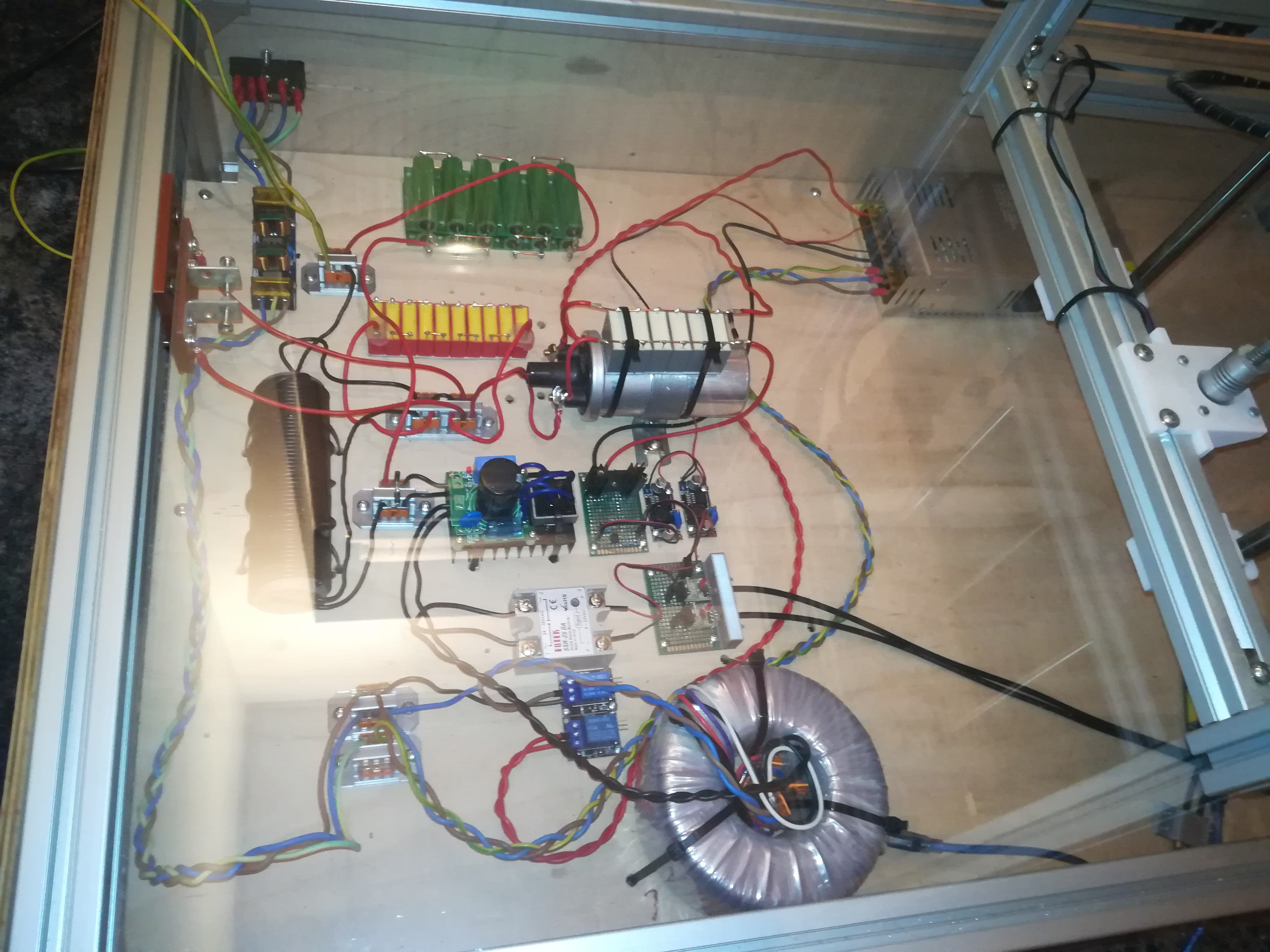
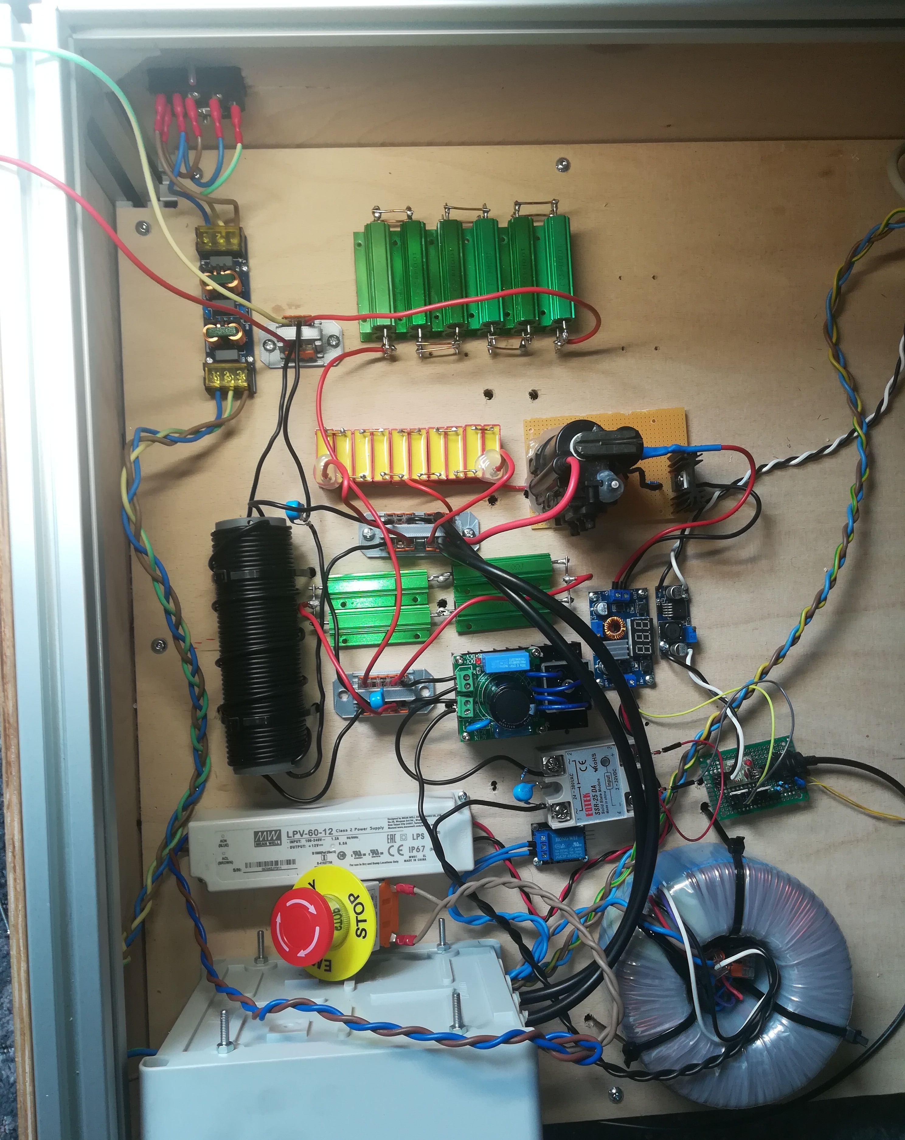
A few Design Changes
09/24/2020 at 13:18 • 0 comments![]()
In the last few days I tried to improve the circuit to get it ready for long operation times.
Things that I changed are:
- Replaced the transformer to get 60VAC 500VA, rectified around 86VDC open circuit and around 78VDC with the load.
- Removed the watercooler and added 12pieces 4 ohm 100W resistors to get 12ohm resistance.
- Added a line filter.
- Placed the HV supply on a pcb.
- Replaced the tesla circuit's ceramic capacitor with WIMA FKP1 capacitors.
- Added a capacitor across the coupling coil for filtering.
- Replaced the lightbulp with 4pieces 100ohm 100W capacitors to get 100ohm of resistance to discharge the welding capacitor and prevent random firing of the arc, because of the HF arc charging the rectifier capacitor. (Maybe at some point I will find a better solution, but for now it's ok.)
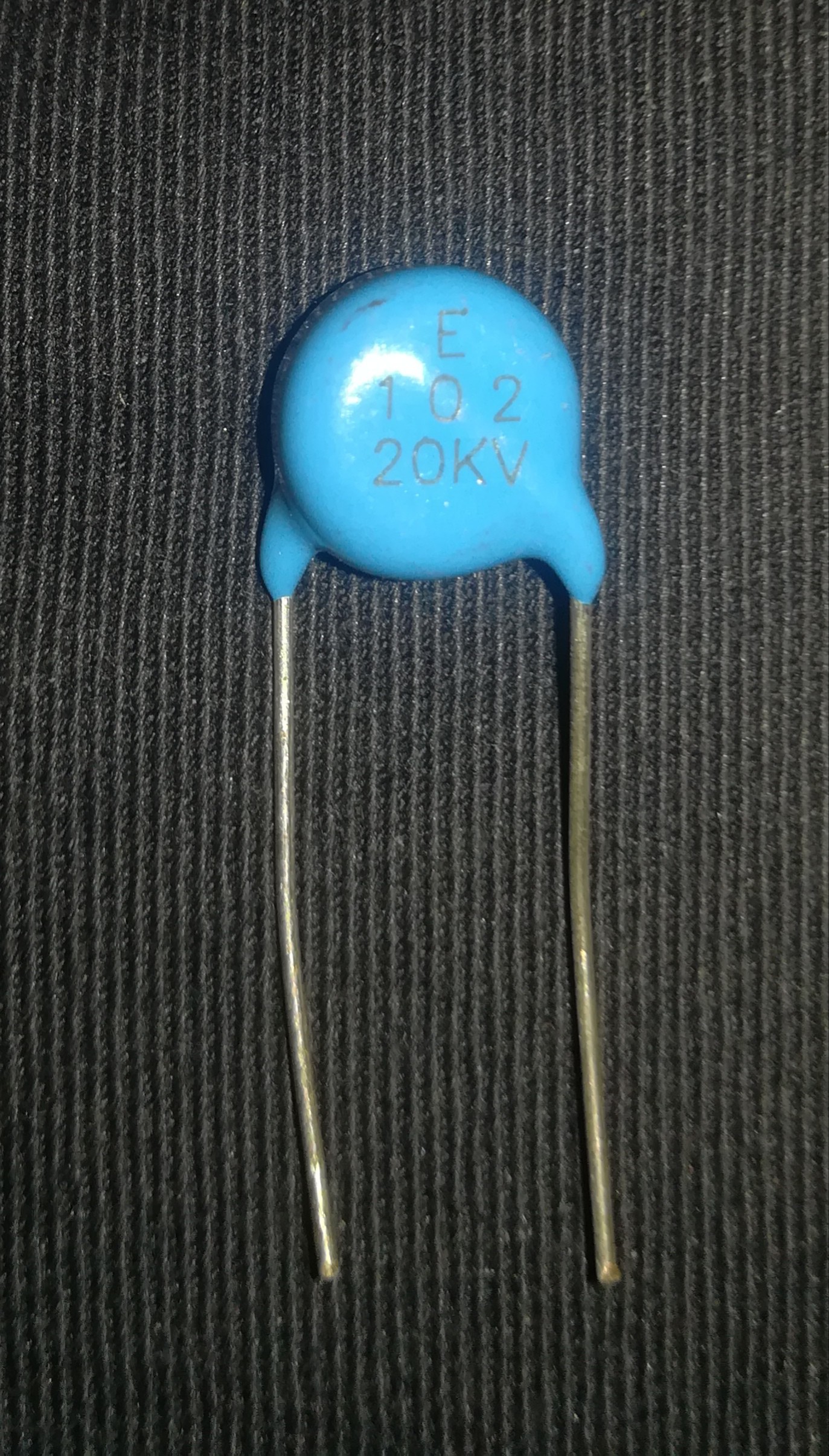
- Got a SSR to work by adding a snubber circuit (1nF 20kV capacitor + 20ohm resistor) to its output and zener diods to its input + switching it with 12V.
The next thing will be changing the optical trigger so that the HF arc and welding arc can be controlled separately.
![]()
![]()
-
Protecting the Welding Circuit from HV + Workaround
09/10/2020 at 13:51 • 0 commentsWhile testing today, I figured out that the HF Start loaded the rectifier capacitor, even when I put a MOV or capacitor in parallel. That caused a decrease in arc strenght and after loading the capacitor to a certain voltage an high power discharge on the tungsten electrode.
I tested it again with nothing but the HF Start coupling coil connected to the rectifier and its capacitor still gets loaded, so it is definitely caused by the HF Starter.
By connecting a capacitor in parallel together with the 400ohm resistor in series to the rectifier + reducing the electrode to workpiece distance, I could reduce the loading of the rectifier capacitor to a minimum. Thanks to @Bharbour for the great advice.
The next problem was that as soon as there was a voltage from the welding source on the welding lines (open circuit), what also included a charged rectifier capacitor, the HF Starter arc did no longer work for some reason.
But at the end I was able to get it to work with a simple workaround - Maybe no permanent solution, but for now it's good because it works.
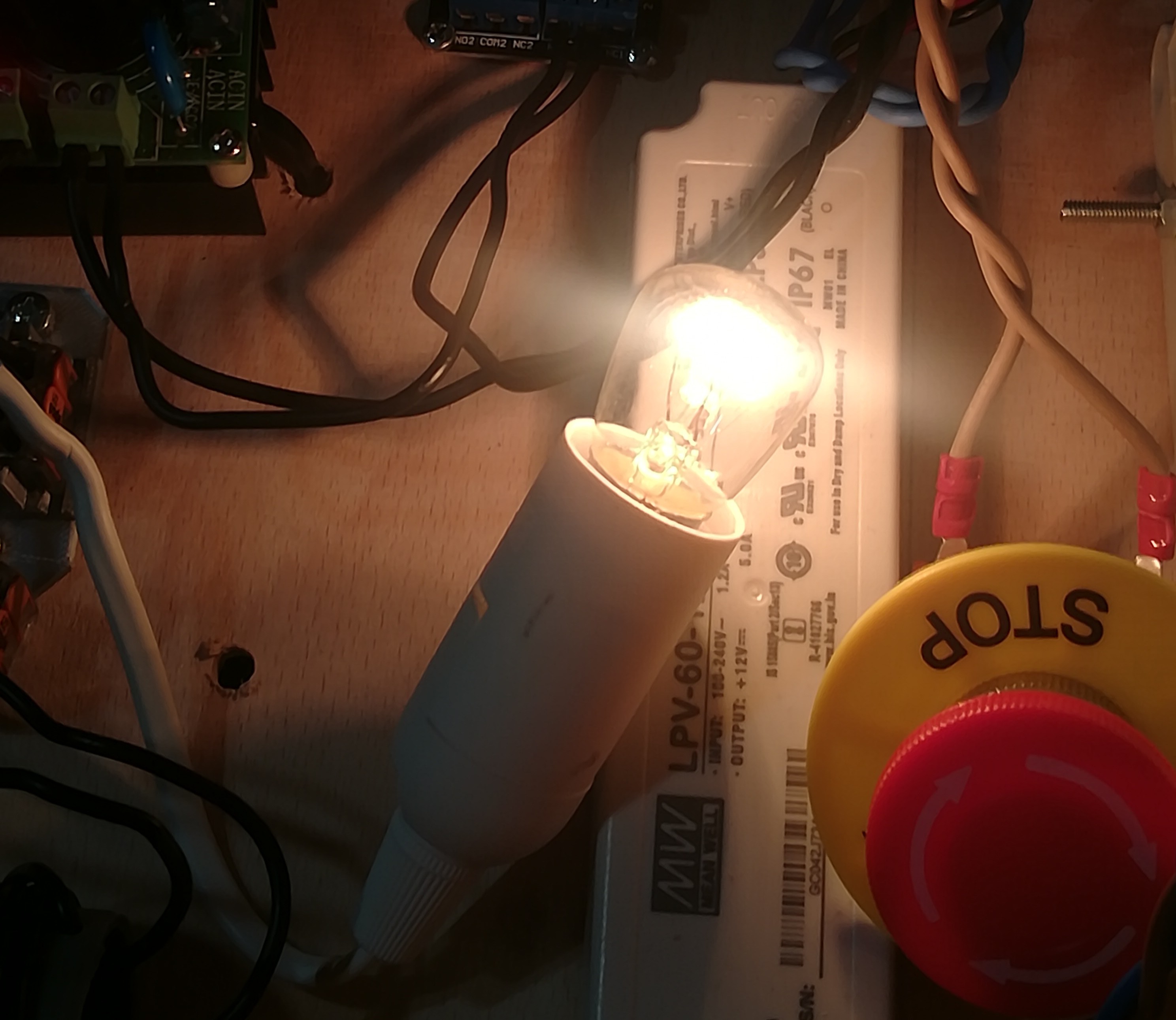
![]()
I added a 15W lightbulp as load to the rectifier to discharge its capacitor as soon as there is no longer power from the welding source, what starts the HF arc again. The lightbulp also indicates that there is power from the welding source on the lines what is also a good thing, so maybe I will keep it.
I think there will be a lot to do in terms of emi/rfi protection, what could end up to be really complicated. I will try many things out and hope that I can find a solution for it over the time.
-
Destructive testing and Continuous HF Start
09/08/2020 at 14:32 • 4 commentsI spent the weekend testing stuff to destruction - not intended but I figured some things out.
- I tested a DC SSR which either never worked or failed at the very beginning.
- An AC SSR before the rectifier seems to work for now.
- The four 100W 100ohm resistors seem to get too hot (even with the active cooling) for continuous operation, so I maybe will try something different for current limiting, like an inverter circuit or a saturable reactor.
But the part I want to get right first is the HF Start Circuit.
Initially I had planed to pulse the HF Start and Work Current together to keep the temperature on the powder not higher than needed and to put less stress on the electronics.
But while testing this I figured out that the arc ignited not every time and the HF HV ignition arc got weaker over time until at some point the HF Starter stopped working completely.
After that I spent some time building an arc detecting circuit which could detect whether the arc has ignited and turn on the HF Start if it would extinguish. (Which I will likely never use).
I stopped working for a day because I had the false assumption that the Flyback transformer was the part that had failed and I ordered a new one and some parts to build a different flyback driver, until I tried building a new simple single mosfet driver (IRFZ44N + 470ohm resistor on the gate + 6+6 turns flyback/primary coil) for testing the transformer and... the transformer still worked. So the driver must have failed which I think was caused by turnung it on and off at a high frequency. I tested the same driver (6 IRFZ44N in parallel) with the transformer for half an hour and it did not fail, so I think the problem was not caused by mosfet overheating, but by the high frequency on and off switching.
With the driver I built yesterday I tested out the HF Starter again and the HF HV iginition arc got still weaker over time until even the spark gap stopped working. I disconnected the transformer from the circuit and it still worked and so it could only be the capacitor which must have had failed and this was the case. After replacing the capacitor with a new one it worked again, but after a short time the arc got weaker again until the capacitor failed again.
I think what happened was the capacitor (a 20kV 1nF Ceramic one) failed over time due to the high frequency of loading and unloading through the spark gap.
So I ordered 10 pieces WIMA FKP1 15nF 1600V DC capacitors which I'm planning to connect in series to increase the rating to 16000V DC 1.5nF. I read in a tesla coil forum that they are better for the high frequency and I hope they will not fail like the ceramic ones.
I think if I can get the hf hv ignition arc to work continuously I can just pulse the work current whit the SSR and everything (maybe) will be fine. Until the next problem appears :)
I figured out the reason for the death of many ceramic capacitor beside that they are not suited for HF. It was the spark gap. For some dumb reason I set it 3 times as wide as planned what leaded to the premature dead of the capacitor after under 2 minutes.
I set it to 2mm what I think should give me around 6000V and with a fresh capacitor it is enough for a 5mm spark at the tungsten electrode. I will test out how long the ceramic capacitor will last until it gets destoyed (they are not expensive).
![]()
The capacitor (still the ceramic one) lasted over an hour and would likely continue working for a long time without failing completely, but it was clearly visible on the arc that it was no longer working at "full power". I think/hope the WIMA capacitor will perform even better, but an hour is not bad and enough for testing some things out.
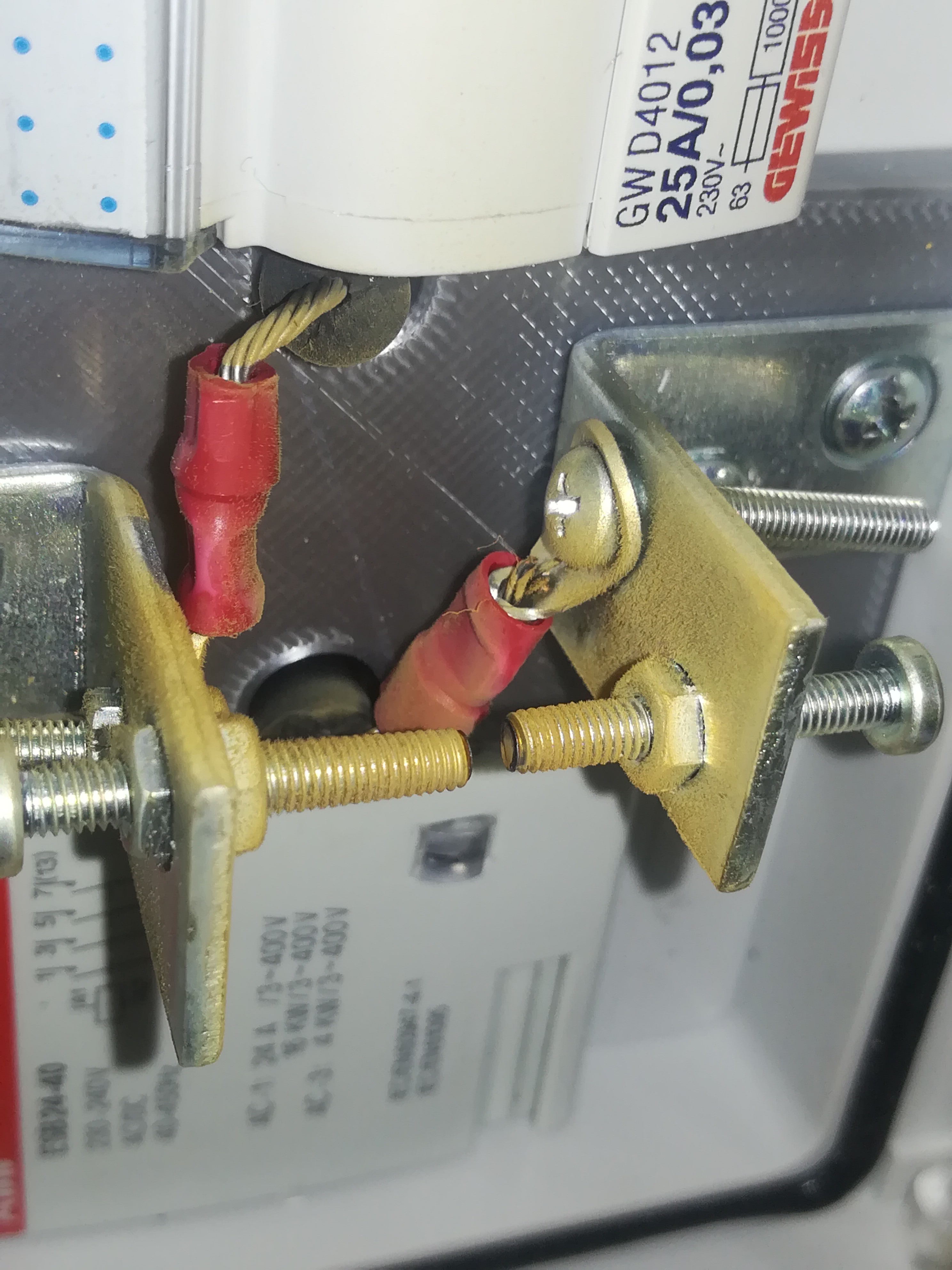
![]()
After letting it run for about 1.5 hours the spark gap was covered in an unknown (by me) yellow dust.... maybe it could be vaporised metal from the screws.
Does anyone know what that dust is?
After turning the machine off for a moment and on again, the arc was back at normal power. So maybe the capacitor was not so heavily damaged like I thought or even not at all.
So for now I will stay with the ceramic capacitor and single mosfet driver until a better one will be needed to keep the design as cheap as possible with good available parts (like flyback transformer, 20kV 1nF capacitor, IRFZ44N + heatsink, 470Ω 1/4W resistor, spark plug cables, MOV). I will likely look for another spark gap screw material, because I don't like the yellow dust on it...
Simple Arc Welder & Optically Controlled Plotter
A simple arc welding circuit with high voltage arc starter and an optically controlled plotter.