-
Scope Probing
09/28/2020 at 16:07 • 0 commentsOne issue I've often faced when debugging boards is scope probing. So, I usually include header pins with a dedicated ground at each place I'd like to view a signal. I prefer the through hole header pins to the surface mount because they are a bit more difficult to rip off of the board.
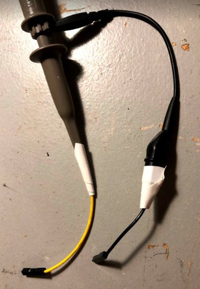
First, I prepare the scope probe. I take a header wire, connect to the probe, and then wrap with electrical tape. I do this for the signal line AND the ground line. I do this for the ground connection (usually an alligator clip) because I have been burned before when the ground connection pops off the connector and drags across the PCB, shorting stuff out as it goes. This method does add a bit of length to the path between signal and ground, but it is fast and a bit safer to move the probes around if you are trying to quickly check something.
![]()
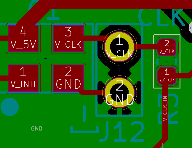
Next, in the board design, I made up a 2x1 header footprint, and include a "-]" text near the ground to give a visual reminder where to connect the ground. On my scope, the grounds are all common, so if you connect the ground to the wrong pin, you run the risk of shorting out something. So, I always like to have an extra reminder of where ground is. Below is "J12" (maybe should have called it TP12?), at the output of the 20 MHz clock.
![]()
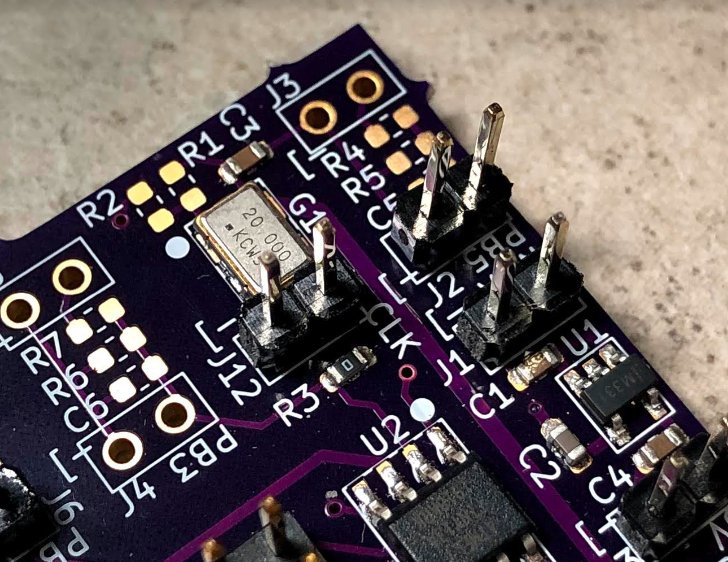
Below is the picture of the populated board, with the header ready for probing.
![]()
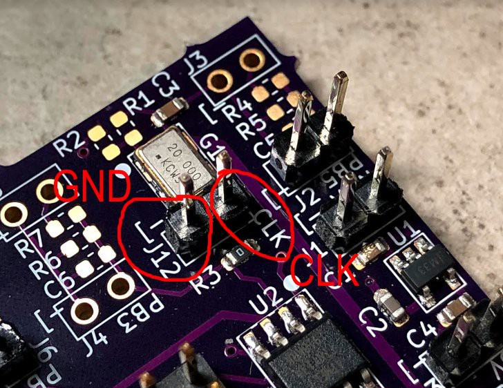
Here is the annotated picture of the PCB just to draw attention to the ground (GND) and clock (CLK) connections.
![]()
-
LTSpice Simulation Files
09/24/2020 at 15:07 • 0 commentsI uploaded the simple LTSpice simulations - one simulation for when the inductor is connected to the 12V supply, the other simulation when the inductor is connected to ground.
-
WRL files posted
09/18/2020 at 02:51 • 0 commentsHi! I posted a couple example WRL files that I made for KiCAD for the PCB rendering. They are simple, and slightly transparent to help visualize the board.
-
Now what? Well, celebrate with video games...
09/16/2020 at 15:20 • 0 commentsNow that you have a supercapacitor all charged up, what do you do?
Celebrate with video games!!!
https://hackaday.io/project/174850-stop-dead-batteries-for-wireless-controllers
-
Video showing the supercapacitor charger with a wire
09/14/2020 at 13:32 • 0 comments -
Video showing the charging of a 450 F supercapacitor
09/14/2020 at 13:29 • 0 comments -
Code
09/14/2020 at 03:42 • 0 commentsHere is the code to the controller. Note in the charging phase there are three steps. First, have the high side transistor on (to increase the inductor current), second have the low side transistor on (at the start, you actually don't turn on the lower transistor), and lastly, dead time. The dead time is super important because at the start, you want to gradually increase the lower transistor on time so that you don't discharge the supercapacitor if it has an initial charge. Since the switching node of the controller is okay with going a bit negative, you use the body diode of the lower transistor and the dead time to decrease the inductor current until the loops converge. When the loop converges, you shed the dead time in favor of the lower transistor on time.
#include <avr/io.h> #define F_CPU 20000000UL // Use external 20 MHz clock, set to external oscillator in the fuses #include <util/delay.h> const uint8_t MAX_CAP_VOLTAGE = 212; // When charging is done const uint8_t START_CAP_VOLTAGE = 180; // When to start charging - separate these two numbers to give hysteresis const uint8_t COUNT_FET_DEFAULT = 0; // When starting to charge, the lower FET on time const uint8_t COUNT_LOW_DEFAULT = 200; // The starting count for the low side on time const uint8_t CHARGING_LOOP_COUNT = 8; // The number of charging loop cycles between checking the ADC reading and the comparator // Enumerated type for the state machine typedef enum {IDLE, CHARGING} state_var; int main(void) { // Main routine // Variable to hold the state volatile state_var the_state = IDLE; // The low side on time uint8_t count_fet = COUNT_FET_DEFAULT; // The idle time when everything is low uint8_t count_low = COUNT_LOW_DEFAULT; // Setup the ADC, bit 6 set to 1 for internal 1.1V reference, left adjusted (so only read ADCH), and select channel 2 (PB4, ADC2) ADMUX = (1 << 6) + (1 << 5) + (2); // Enable ADC, start it up, auto trigger, no interrupt flag, no interrupt, divide by 128 ADCSRA = (1 << 7) + (1 << 6) + (1 << 5) + (0 << 4) + (0 << 3) + 7; // No analog comparator mux, free running mode ADCSRB = 0; // Analog comparator control, enabled, bandgap turned on ACSR = (1 << 6); // Allow the ADC to settle, and allow for system programming _delay_ms(2000); // Output pins, PB0 for high side FET, PB1 for current sense (comparator), PB2 for low side FET, PB3 for CLKI, PB4 for capacitor voltage monitor DDRB = (1 << 0) + (1 << 2); // Set the output pins to low PORTB = 0; while (1) { // Main loop if (the_state == IDLE) { // Idle state // Wait to let the ADC readings settle _delay_ms(3); if (ADCH < START_CAP_VOLTAGE) { // Begin charging // Initialize lower FET on time count_fet = COUNT_FET_DEFAULT; count_low = COUNT_LOW_DEFAULT; // Update state variable the_state = CHARGING; } } else if (the_state == CHARGING) { // Charging state // Charging loop for (uint8_t ii = 0; ii < CHARGING_LOOP_COUNT; ii++) { // Turn on the high side FET PORTB = 1; PORTB = 1; PORTB = 1; PORTB = 1; PORTB = 1; PORTB = 1; // Turn off the high side FET PORTB = 0; PORTB = 0; PORTB = 0; // Turn on the low side FET for (uint8_t jj = 0; jj < count_fet; jj++) { PORTB = 4; } // Turn off the low side FET PORTB = 0; for (uint8_t jj = 0; jj < count_low; jj++) { PORTB = 0; } } if (ADCH > MAX_CAP_VOLTAGE) { // Done charging, set to IDLE the_state = IDLE; } if ((ACSR & (1 << 5)) == 0) { // Current too high if (count_fet < 255) { count_fet = count_fet + 1; } } else { // Current too low if (count_fet > 0) { count_fet = count_fet - 1; } if (count_low > 0) { count_low = count_low - 1; } } } } } -
Adapter PCB for supercapacitor
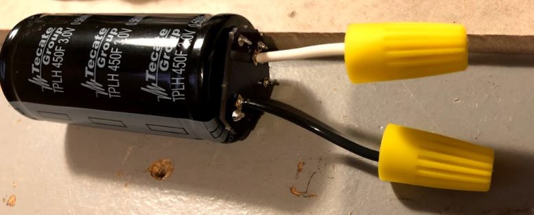
09/14/2020 at 03:37 • 0 commentsJust for reference, I made a small adapter PCB for the supercapacitor. This let's you attach wires to the supercapacitor and use the strain relief of the supercapacitor mounting pins.
![]()
Then you can place twist on connectors to the wires to prevent accidental shorting.
-
Results
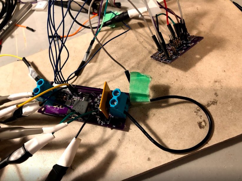
09/14/2020 at 03:34 • 0 commentsSo, the first thing to test is a piece of wire. Yes, crazy, but it makes it easier to debug.
![]()
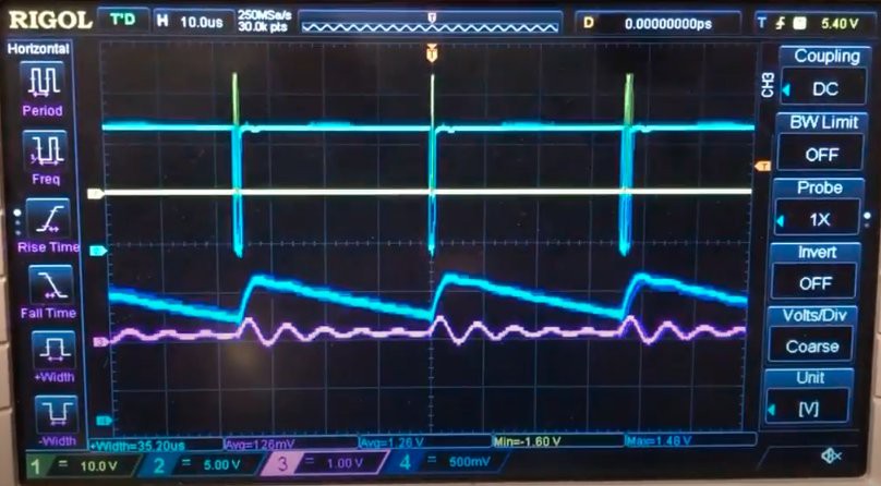
Here is the scope view:
![]()
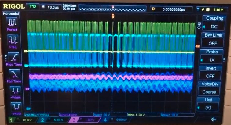
The yellow trace shows when the high transistor is on (briefly to add a bit of current to the inductor). Then, it shows that the low transistor is on for a long time (it takes a long time to reduce the inductor current). The inductor current is middle of the scope and shows the fast rise when the high transistor is on, and the long decay when the low transistor is one. The voltage is purple, and just ripples of voltage (remember, the is just driving a wire).
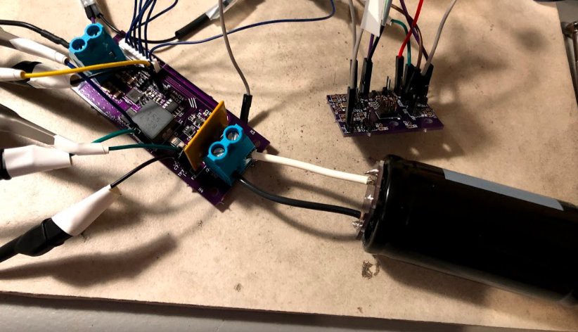
Next, I connected a supercapacitor, and started the charging.
![]()
Here is the scope view...
![]()
So, it worked! It keeps the inductor current hovering around 1.2V (i.e., the 1.2V of the comparator), and the capacitor voltage is slowly increasing.
Total capacitance, 450 F, total charge time from 0.7V to 2.8V, 2 minutes, 53 seconds. So with the untuned controller, the average current was around 5.5 Amps. Next step would be adjust the controller code to tighten up the current ripple (it gets a little sloppy when the capacitor voltage increases past 1 V).
In still air, the hottest component on the board was the low transistor at 50C.
-
Testbed
09/14/2020 at 03:23 • 0 commentsHere is the PCB rendering in KiCAD
![]()
Here is the PCB
![]()
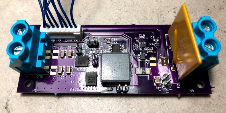
On the left are the screw terminals to apply the 12V. C1-C6 are the input capacitors. The transistors are SIRA20DP. They are controlled by a MP18021. Why the MP18021? It can handle -5V on the switching node. It also has the integrated diode for high side driver. The inductor is a 1uH SRP1265A. The output current is measured using a 0.001 Ohm sense resistor, with Kelvin connections to the INA180 current sensor. There is a small output capacitor. Then, to connect to the supercapacitor (and make sure I don't have ~200 Amps in the event of a short while probing), I used a 15A 0ZRN1500FF1A polymeric fuse. The terminals on the right are for the load. The 8-pin JST connector connects to the controller.
Supercapacitor Rapid Charger
A 6 Amp supercapacitor charger, and a small tutorial on charging
