The Specs
Simple Add-on v2's specs are identical to SAOv169bis. The first pin is VCC, power, and it is expected to be 3.3 Volts. Second pin is Ground / Earth, third pin is SDA, fourth SCL, and the last two pins are for GPIO. The only two pins that are always expected to work are VCC and GND, the other pins are optional. If you are making an Add-on and would like to make use of Pins 3-6 you should coordinate that with Badge / Device makers or at least document it well so that badges that would like to accommodate that can do so.
The Footprint
As this standard remains compatible with the original "Shitty Add-on" standard it uses the same pinout. The supplied "SAOv2.zip" is a updated and renamed version of the original SAOv169bis KiCad Footprints and Libary files that I created in 2019. The changes made to the "SAOv2" part pertain to better dimensional accuracy and changing the square pad from "GND" to "Pin 1" which is VCC.

There are two foot prints provided for your use. The "Badge" Foot print has an outline of the Keyed Female part on the Front Silk screen and on the Back Silk Screen has the pinout labled. On the "SAO" Footprint the front is left completely blank while the back has labeled pins and an outline for the Male header.

The Connector
As this standard remains compatible with the original "Shitty Add-on" standard it uses the exact same parts.
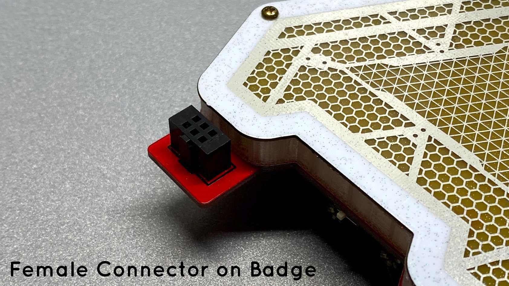
The Add-on board will use a Male 2x3 2.54mm (0.1") Pin Pitch Shield header and the Badge / Host board will use a 2x3 2.54mm (0.1") Pin Pitch Female connector. For mechanical security it is preferred that the female part use a Polarized Keyed part but a non-keyed connector will work.


Obtaining these parts is fairly easy. The SAO side male connector is extremely common and is inexpensive on Amazon or Ali Express. You can get them on Digi-key, Mouser etc as well but they will be considerably more expensive albeit probably higher quality. If you're looking to stretch your dollar it's cheaper to buy in bulk on Ali Express otherwise Amazon will do just fine.
The Female part however is more difficult. If you're building a device to host SAOs you can get away with a regular 2x3 female connector but it will have a poor grip on Add-ons and they will fall off unless the host is stationary.
The two least expensive sources for the female part is either on my (TwinkleTwinkie's) Tindie Store or Ali Express.
Tindie Store Listing: https://www.tindie.com/products/twinkletwinkie/10-pack-of-sao-female-keyed-connectors/
Ali Express Listing: https://www.aliexpress.com/item/33060894189.html?spm=a2g0s.9042311.0.0.28904c4dBFB03G
If you'd rather not buy from myself or China you can get some made to order by contacting a manufacture such as "Sullins Connector Solutions", they are the ones who made the more "Square" Female connectors pictured above. The rounder ones came from China. They are about the same mechanically.
Here is a Digi-Key listing for the Sullins part, but I recommend going to their site and contacting them directly. They are great and easy to work with but you'll be purchasing in minimum quantities of 1,000 and they are not cheap. https://www.digikey.com/product-detail/en/sullins-connector-solutions/SFH11-PBPC-D03-ST-BK/SFH11-PBPC-D03-ST-BK-ND
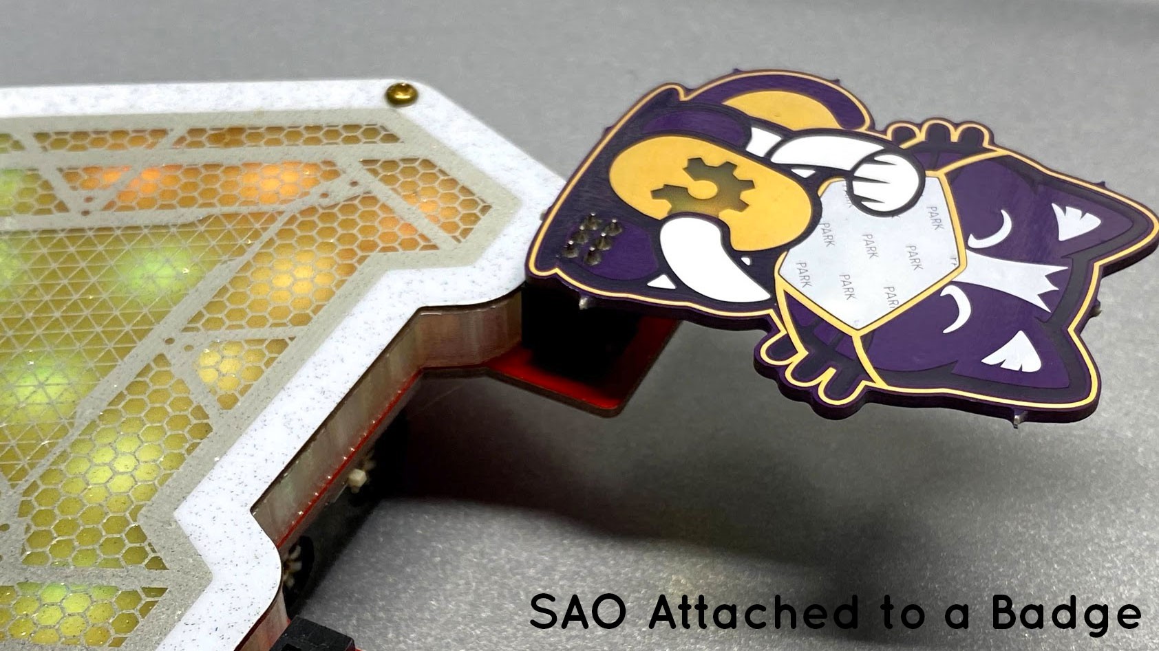
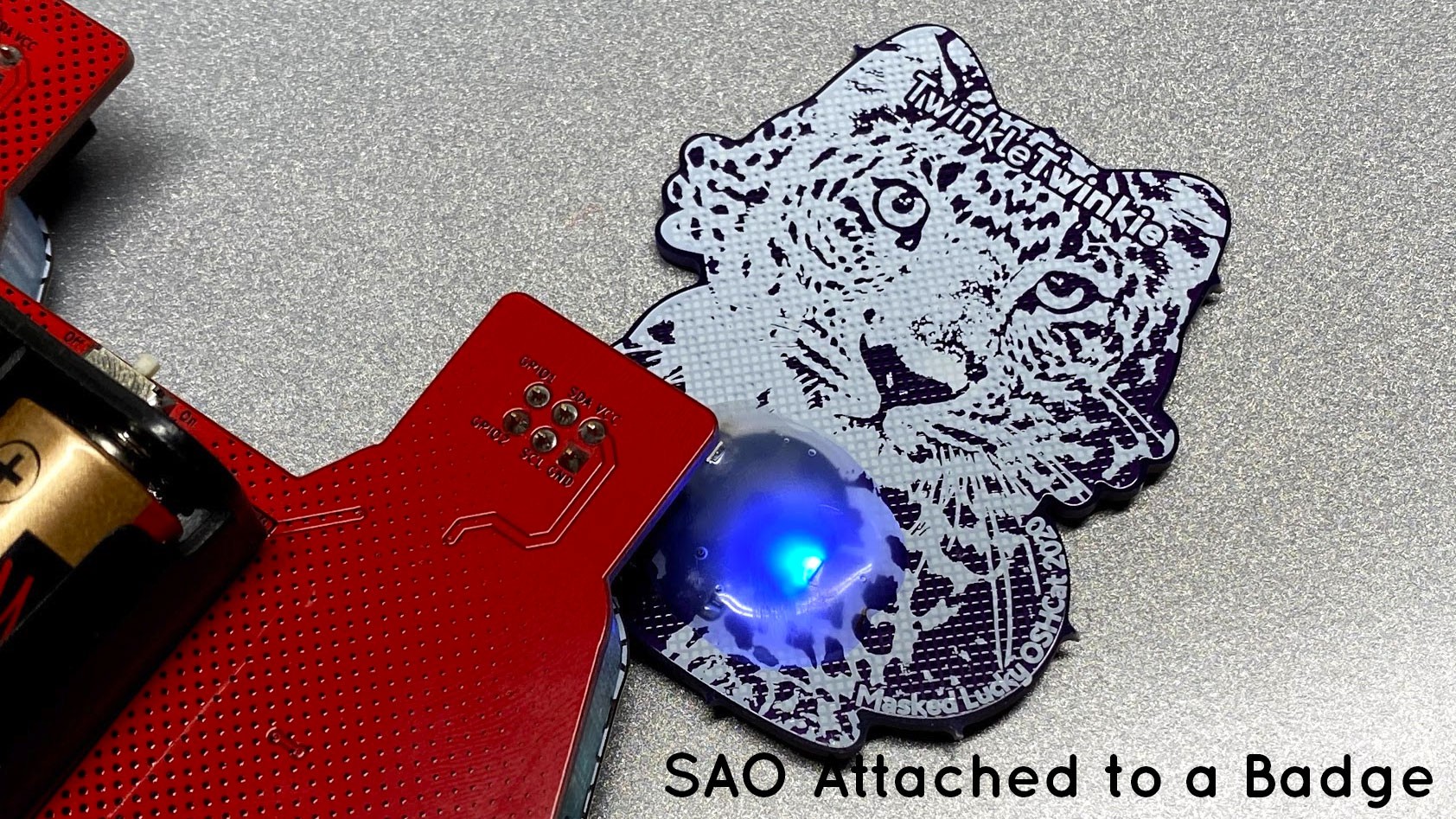
Here are some example pictures of the connector in use for reference.


 TwinkleTwinkie


is VCC 3.3v or 5v?