I wanted to extend the learning that I had done on my 6 Amp supercapacitor charger, and push it to 25A. Here is the previous project:
https://hackaday.io/project/174806-supercapacitor-rapid-charger
The main goal of the project is to increase the charging current, yet still be able to run the charger in still air. Side goals included using a nifty planar inductor and changing over to an ATMEGA328PB.
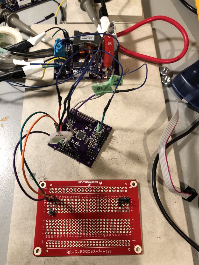
Here is the whole setup on the bench:

At the top is the 2 oz perfect purple PCB that carries the switching MOSFETs, inductor, 50A fuse (safety!), driver and current amplifier.
The middle board is an ATMEGA328PB evb that I designed (20 MHz external clock, and voltage dividers/filters for the comparator and analog to digital converters).
The bottom breakout board is the "chicken button". When you press the button, the 328PB executes the charging code. When you release the button, the 328PB stops. I was playing with higher charging currents and different parameters, so sometimes the switching MOSFETs can get a little warm, and you want to be able to stop the charging if things start to go into thermal runaway.
The first thing to test is applying the charging current to a wire (when the supercapacitor is completely discharged, it will act like a short circuit). Here is the oscilloscope view of passing the ~25 A through the wire.
The top two traces are the switching voltages (channel 1 for the high side MOSFETS, channel 2 for the low side MOSFETs). Channel 3 is the voltage at the input to the inductor. Channel 4 is the current amplifier output. The current sense resistor is 300 uOhm, the amplifier gain is 200, and output voltage of the current sense amplifier is ~1.5 volts. So, 25A is flowing through the wire. The ATMEGA328PB is controlling the current by monitoring the current amplifier output using the comparator. If the comparator output is low (indicating the current is too high), the controller will decrease the inductor current by increasing the "on-time" of the low-side FET. If the comparator output is high, the controller will increase the inductor current by decreasing the "on-time" of the low-side FET.
Here is the lab video showing the charging of a 450 F supercapacitor. You know the charging is done, because the capacitor hissing stops! The ATMEGA328PB shuts down the charging when the capacitor voltage is about 2.8 V (this is a 3 V supercapacitor, but I wanted a bit of margin).
To charge the supercapacitor from 0.67 V to 2.81 volts takes approximately 40 seconds, so the average charging current is about 24 amps.
if you have low Vgs- how many transistors are you driving from the TI part? If you have something like two or three, maybe there isn’t enough drive strength? What is the total gate charge?