Nikola Secerovski
-
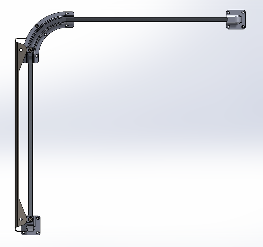
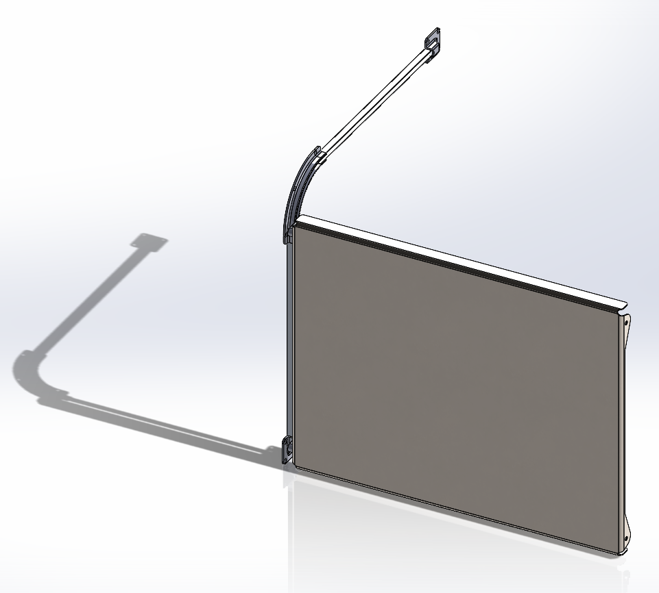
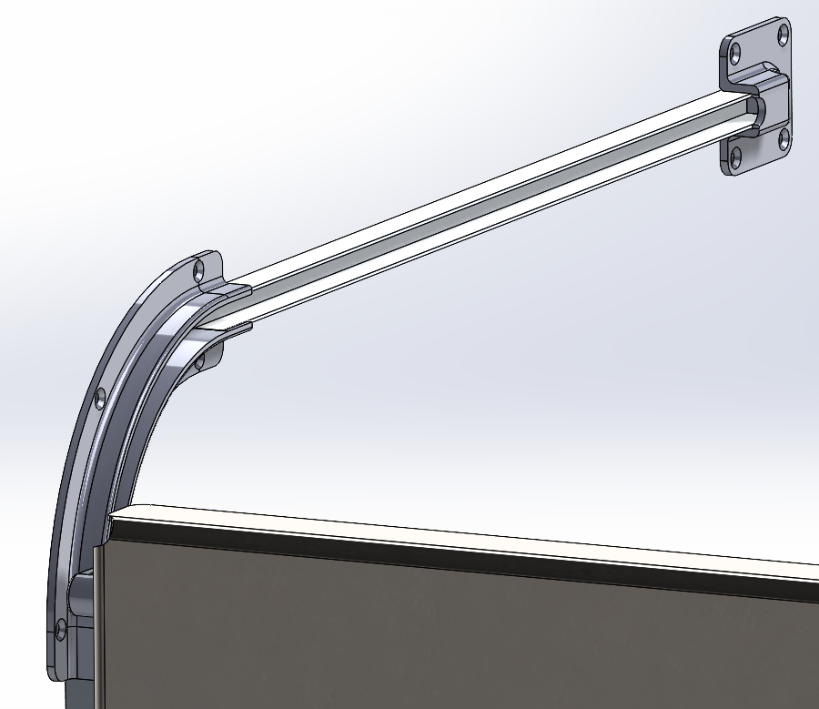
Electric sliding door concept
05/12/2021 at 06:40 • 0 commentsHere is an idea for the sliding electric front door, it uses aluminum U profiles and some 3D printed parts. Door itself is made from bent aluminum sheet. Here are some pictures...
![]()
![]()
![]()
-
PART_4.STL [IEC Connector housing]
02/08/2021 at 12:37 • 0 commentsJust added PART_4.STL file to the GitHub repository. This is a IEC connector housing for the arcade cabinet.
![]()
-
Progress update
01/31/2021 at 13:26 • 0 commentsThe to do list for this project is getting smaller and smaller. There are few more things left to do:
- Replace RPI 3 with 4 and properly mount it
- Connect the microphone (I was wrong about audio input, so i ordered USB sound card)
- Make electric front door (This will become a new project)
- Print screen bezel (Transparent PVC foil overlay)
- 3D print recessed housing for IEC power connector, so it doesn't stick from the back of the cabinet
- Make new cabinet back (Laser cut .75mm galvanized steel sheet)
-
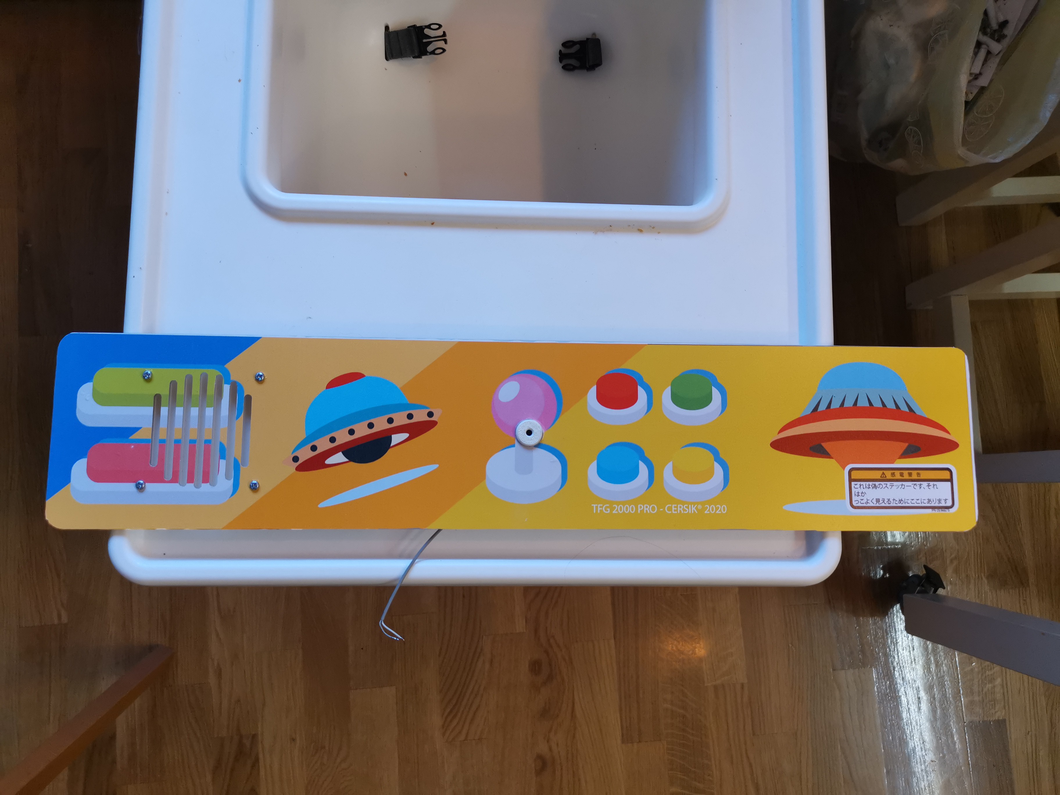
Printing arcade graphics
01/31/2021 at 13:15 • 0 commentsI have just added pdf file to git repository that I used to print arcade graphics. If someone decide to use this template, just be aware of the dimensions, i left no room for error, everything must line up, as it ends up, it was a mistake :)
-
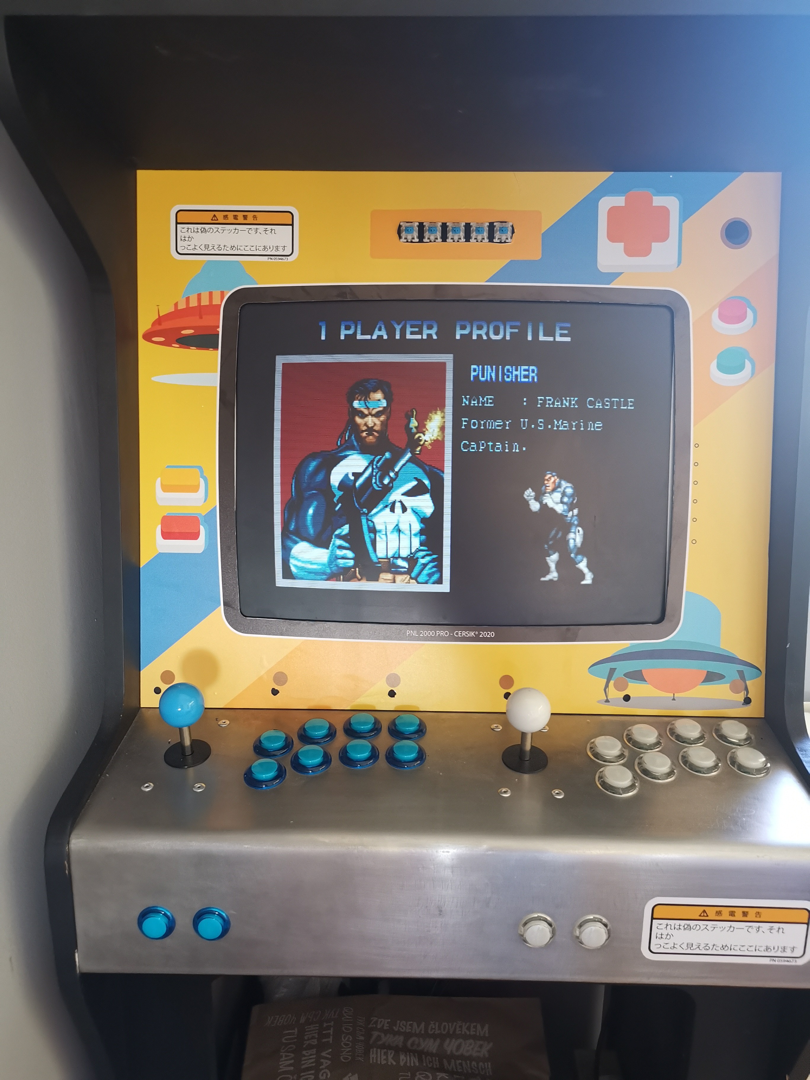
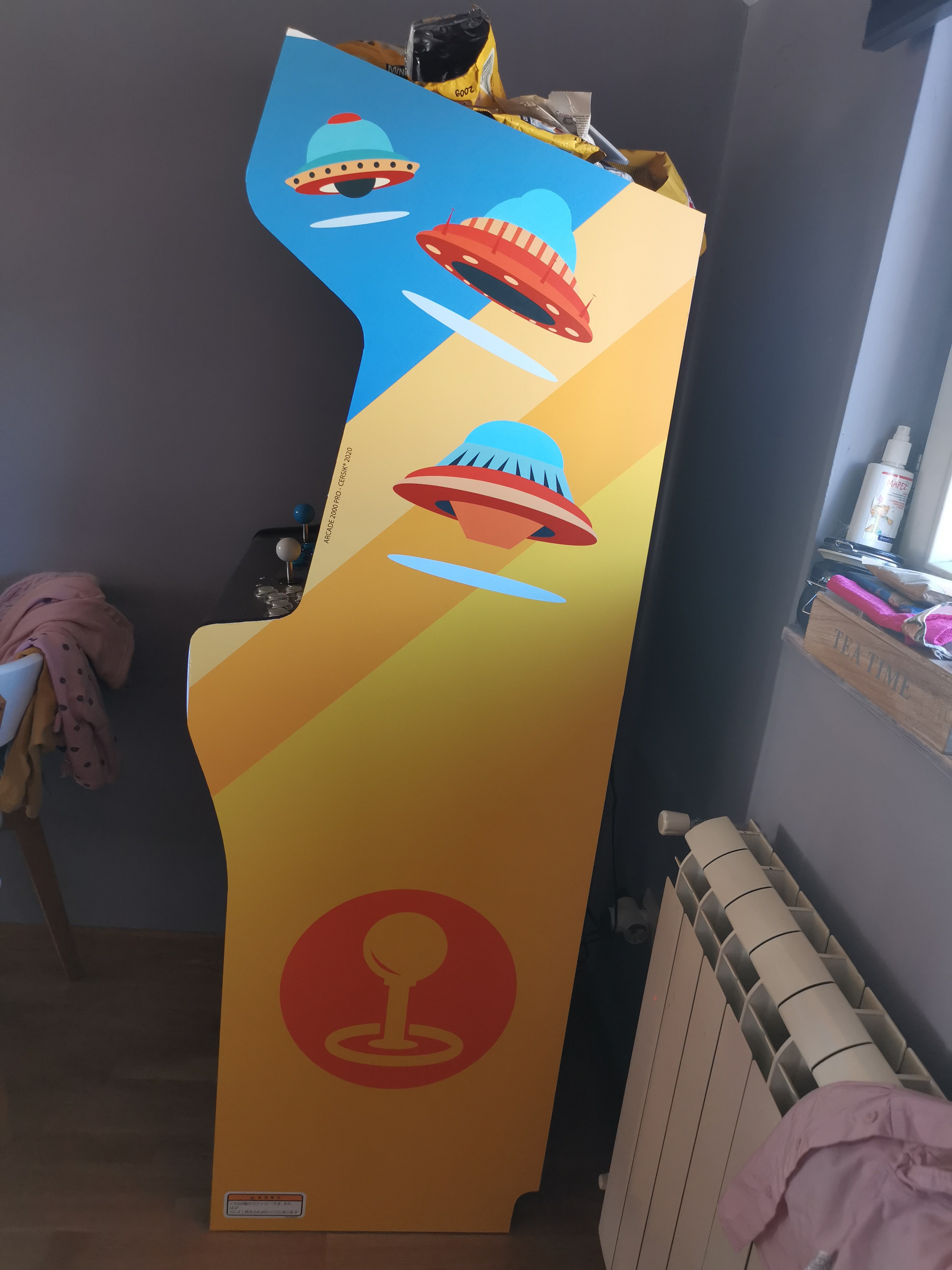
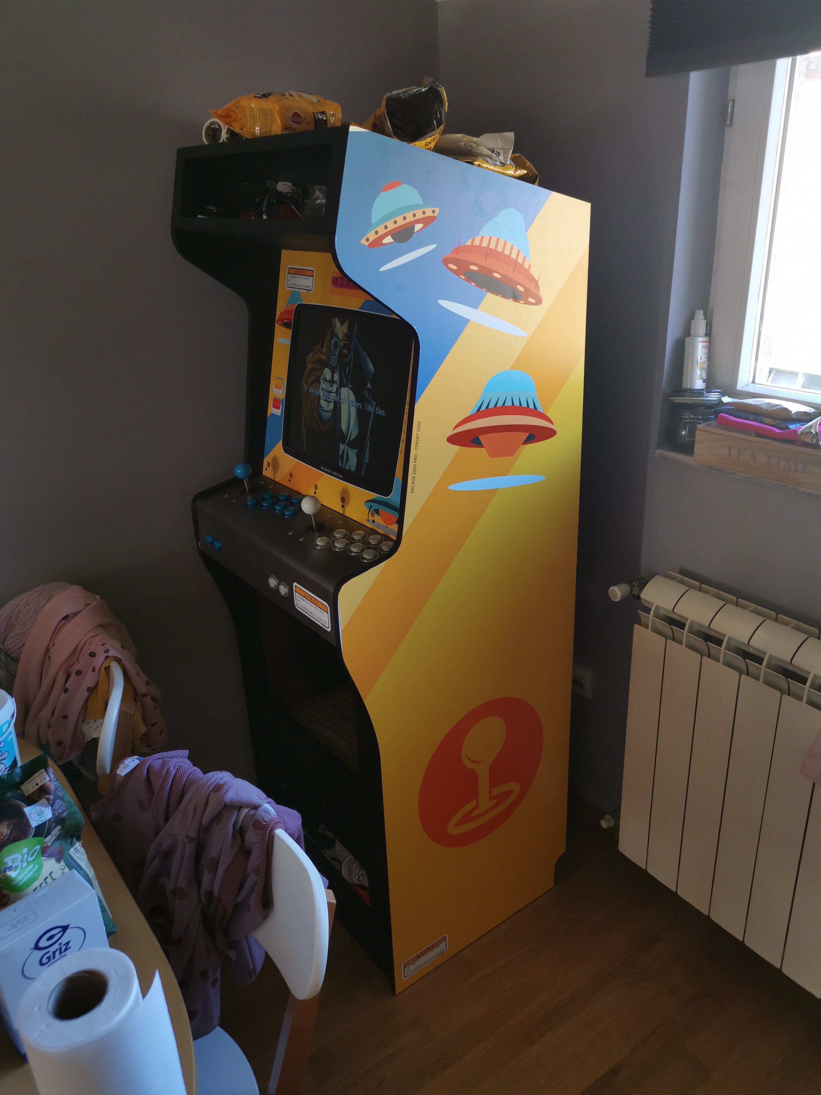
Wrap it up
01/31/2021 at 08:25 • 0 comments![]()
![]()
![]()
![]()
![]()
![]()
![]()
![]()
-
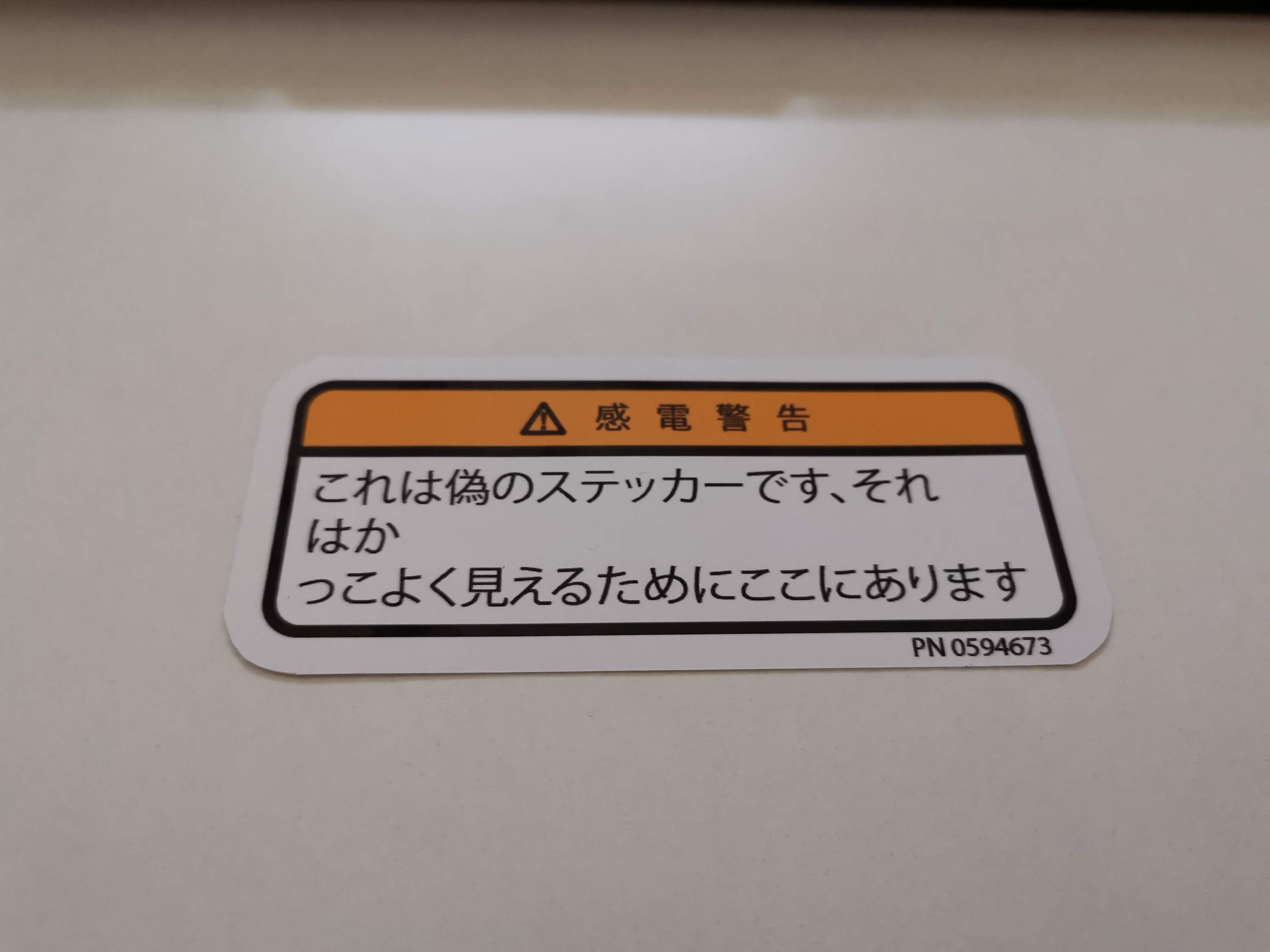
Got some stickers?
01/29/2021 at 12:05 • 0 commentsPrinted vinyl stickers have arrived! Here is the preview...
![]()
-
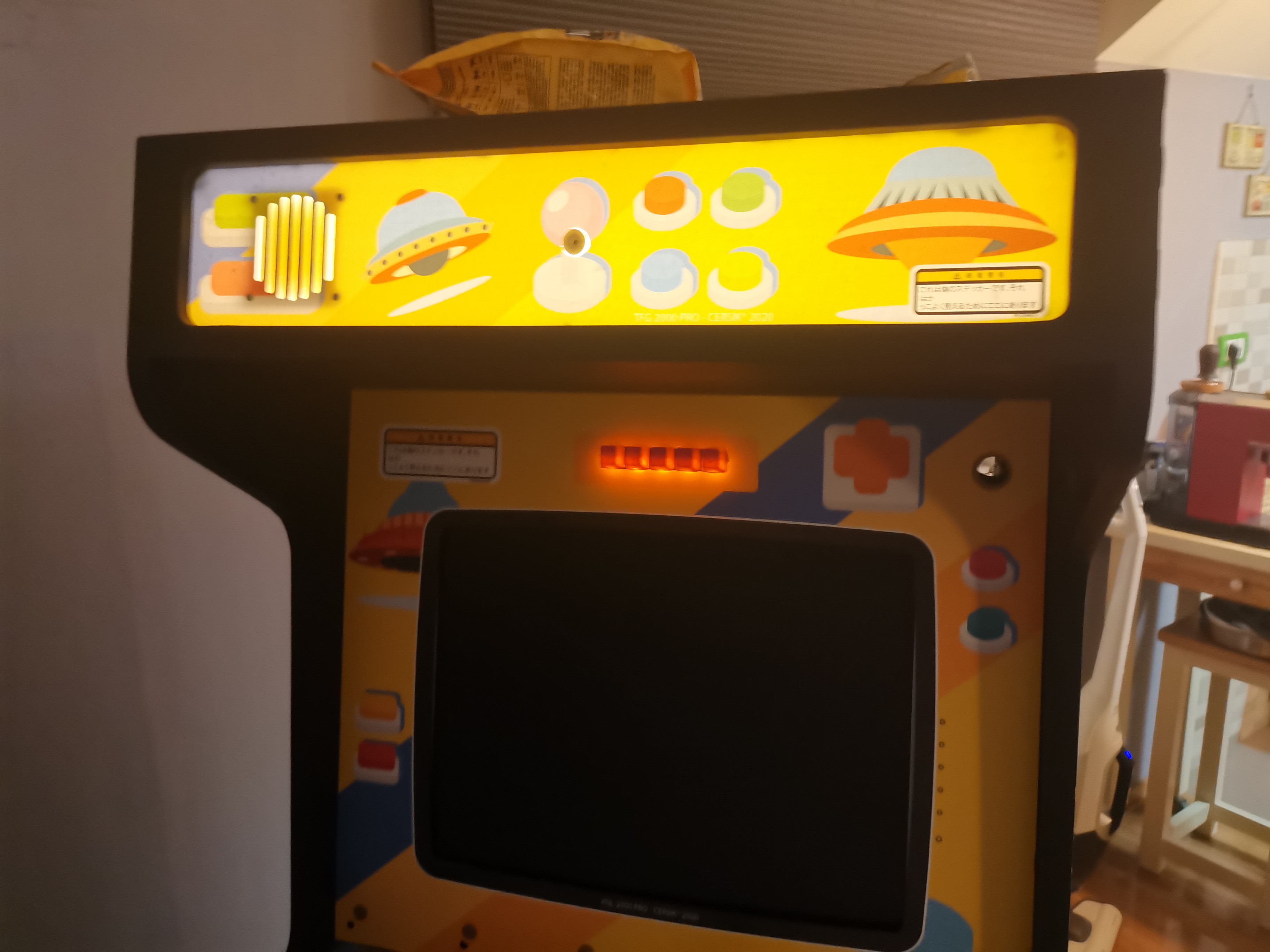
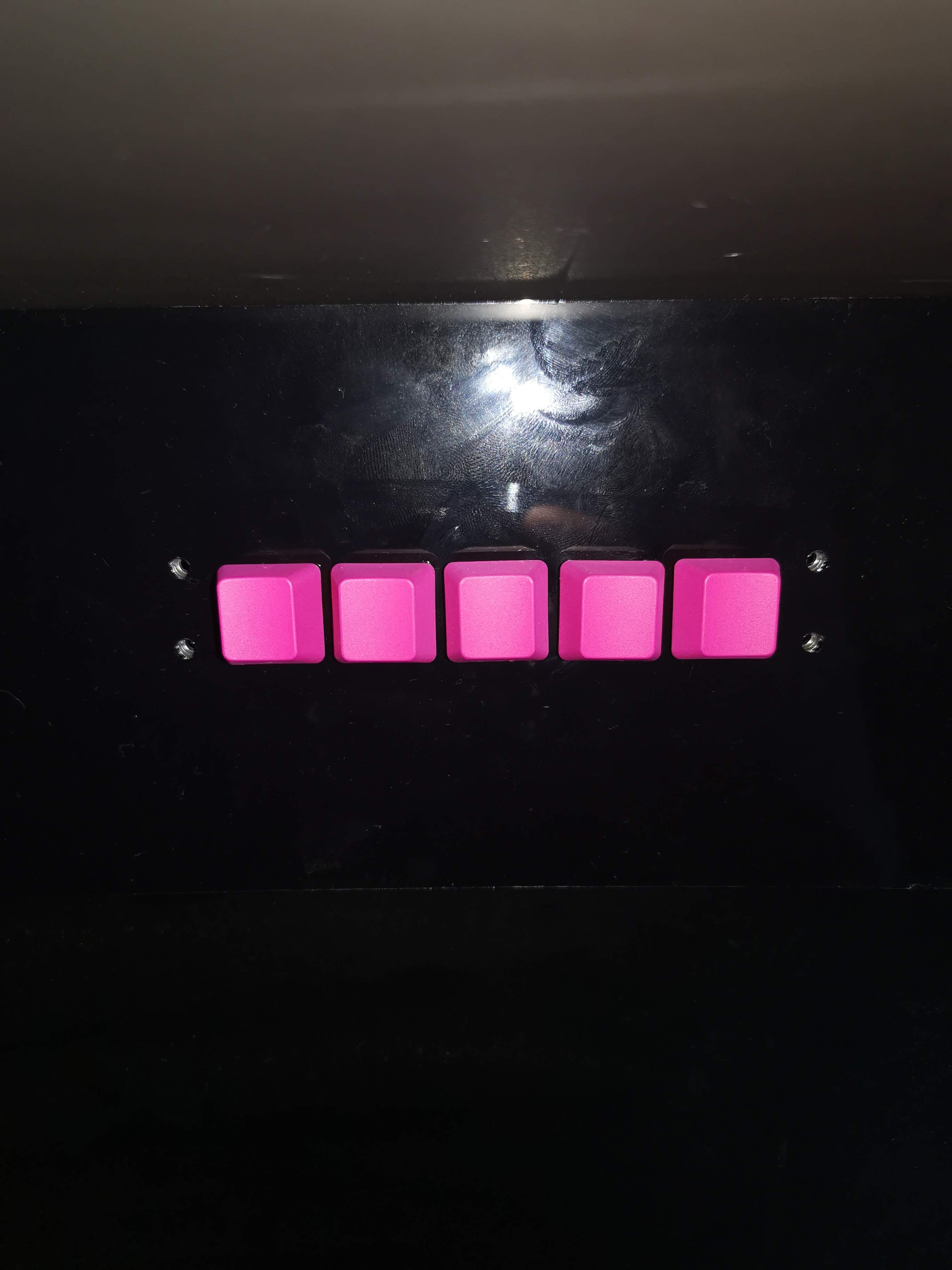
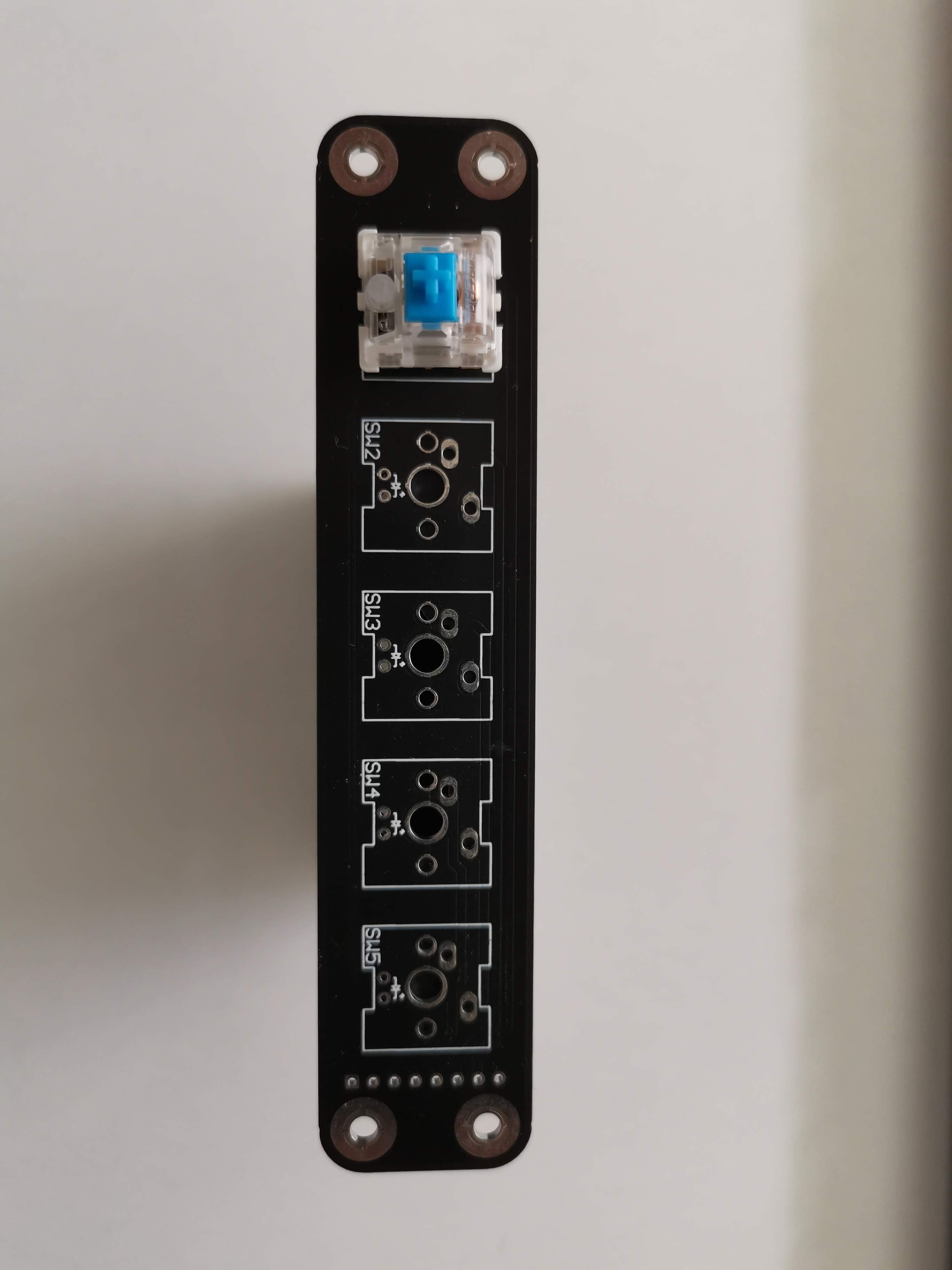
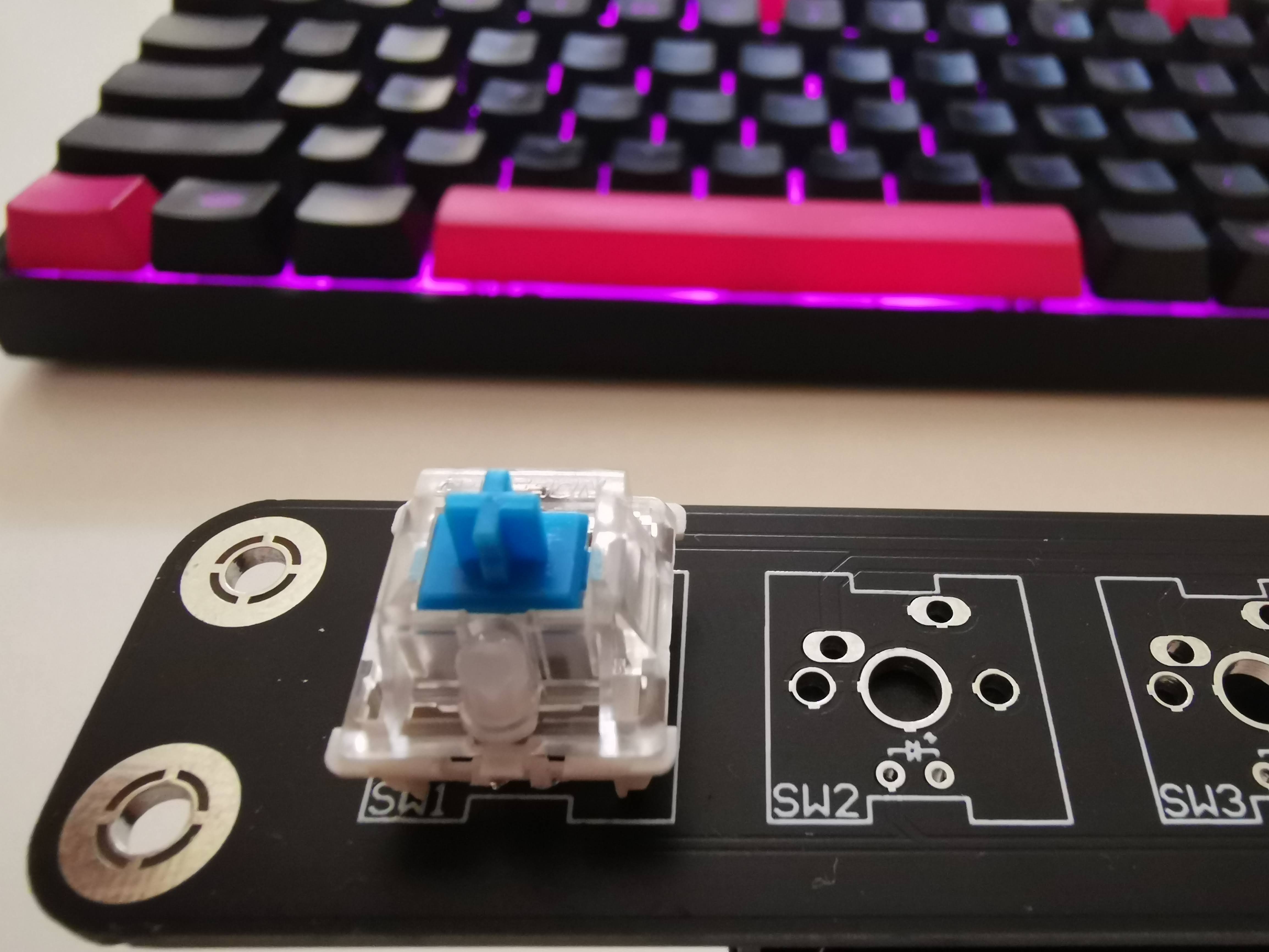
Front panel keypad
01/26/2021 at 11:00 • 0 comments![]()
-
Wiring (I'm lazy)
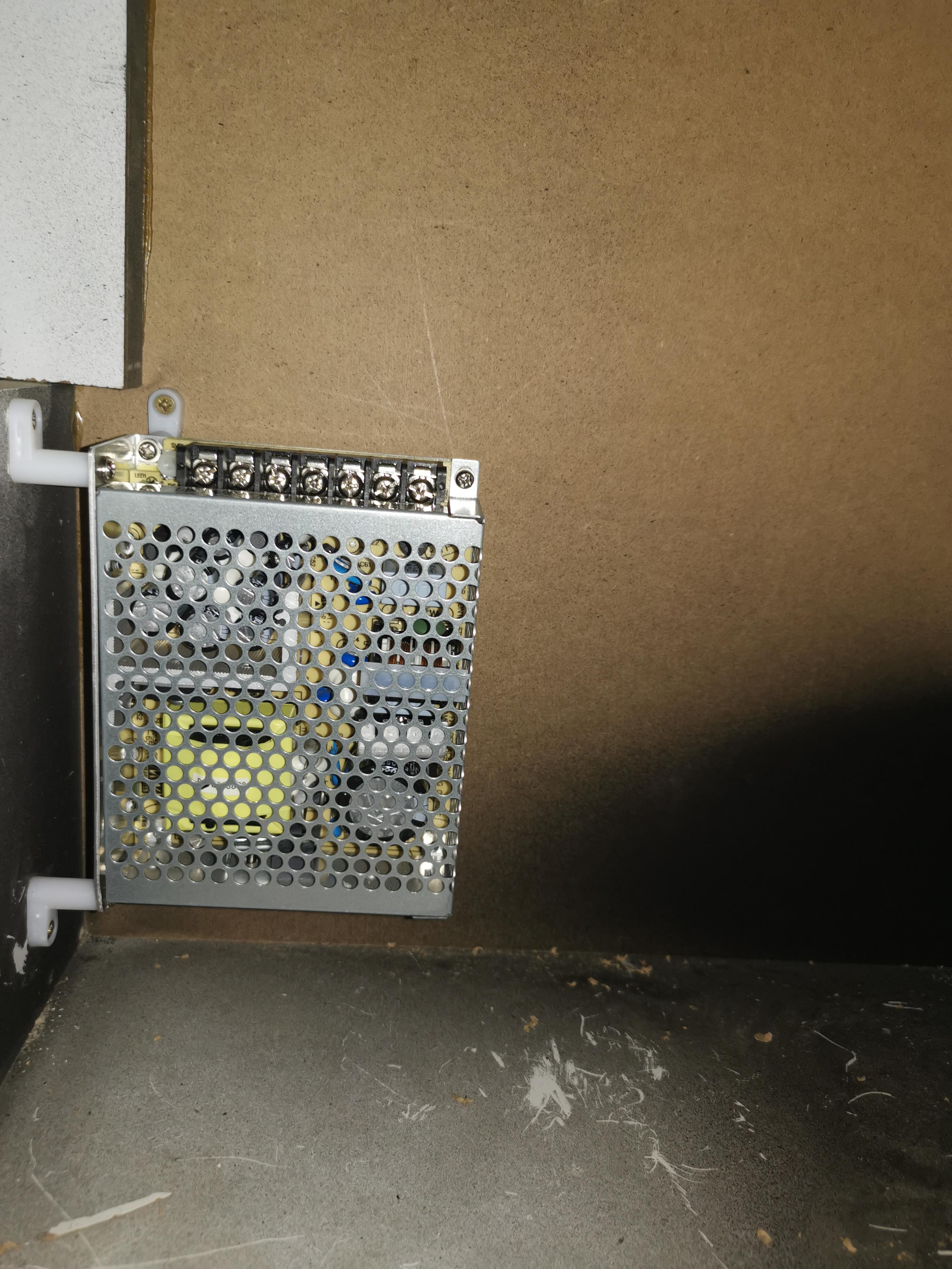
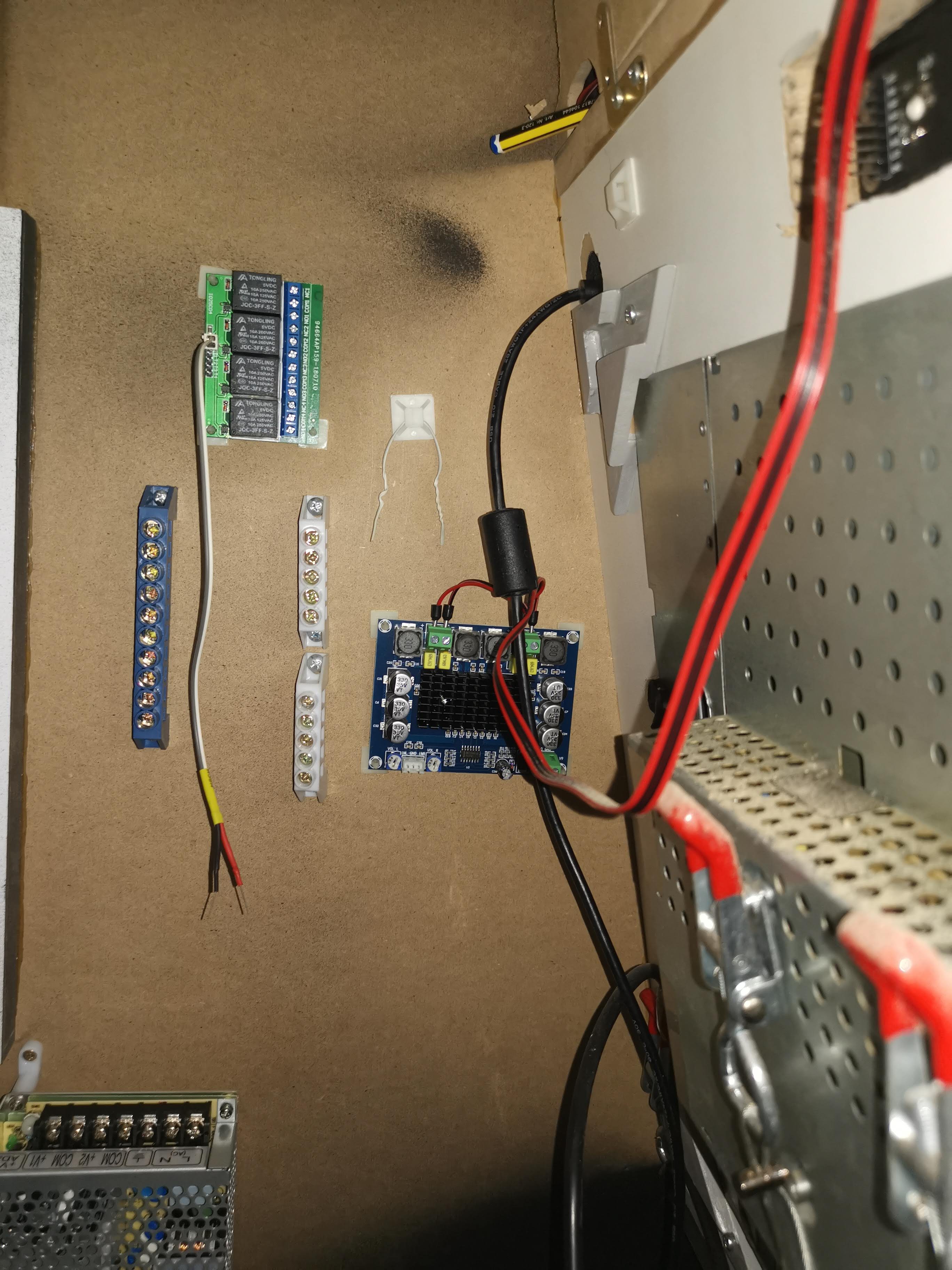
01/25/2021 at 10:01 • 0 commentsThis item on the arcade check list i long-overdue, all the components have arrived weeks ago, but i was to lazy to do this task. These are the components I put together:
- Power supply (Dual rail, 5V + 12V, SMPS)
- Latching relay module board (4ch)
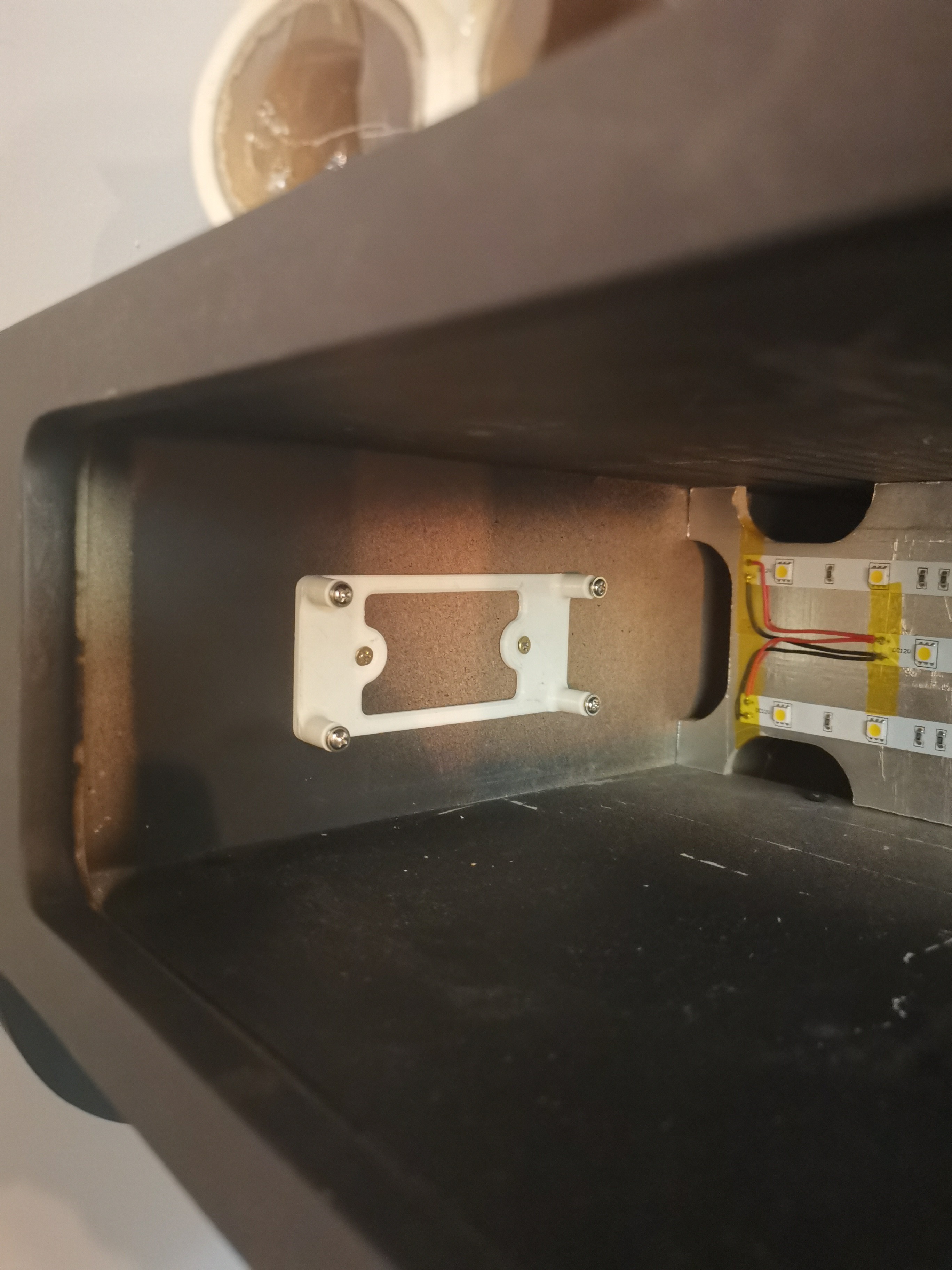
- Audio amplifier (D-Class)
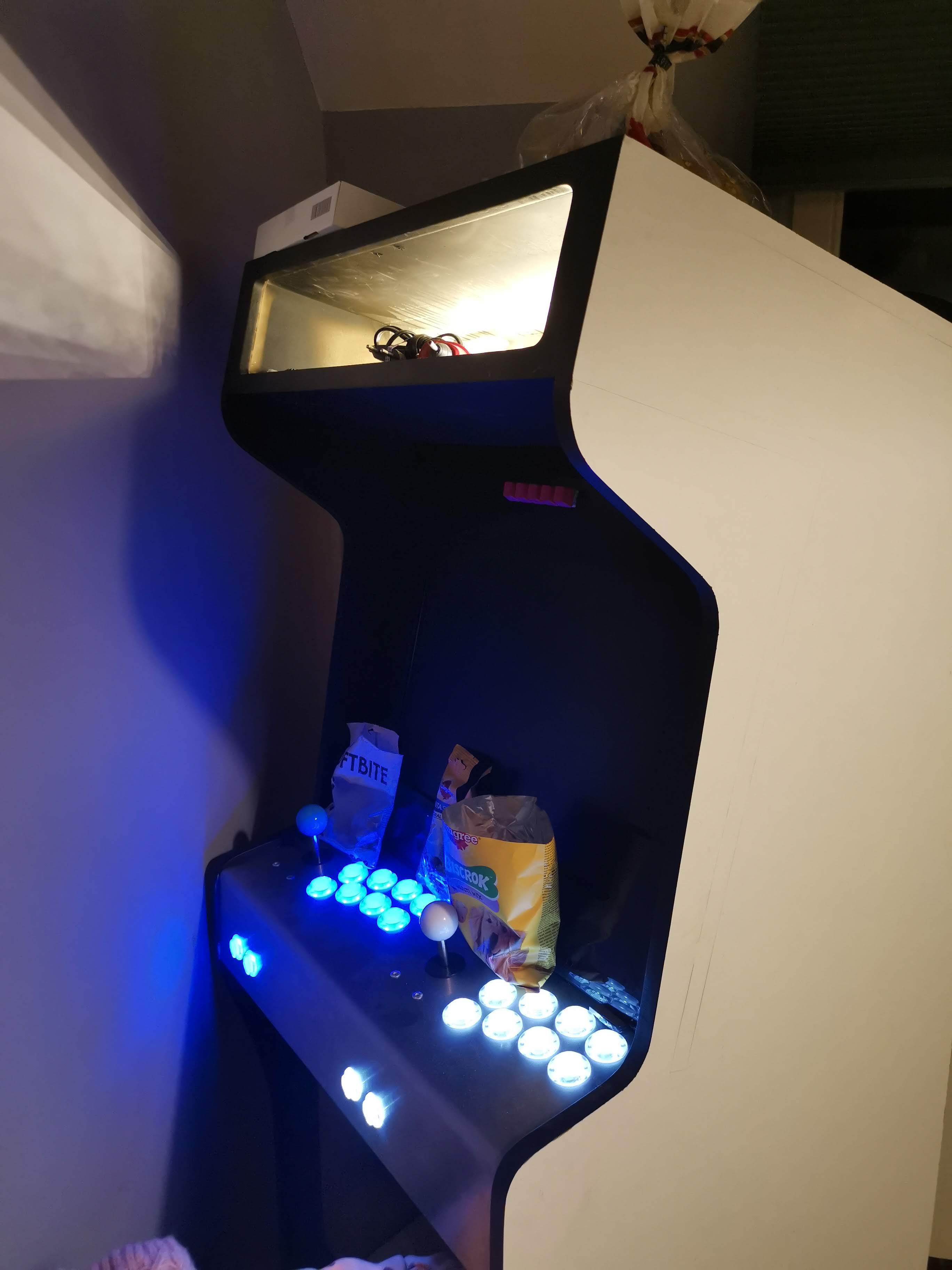
- Marquee LED backlight
- Controls backlight
- Front panel keypad
- Raspberry PI 3
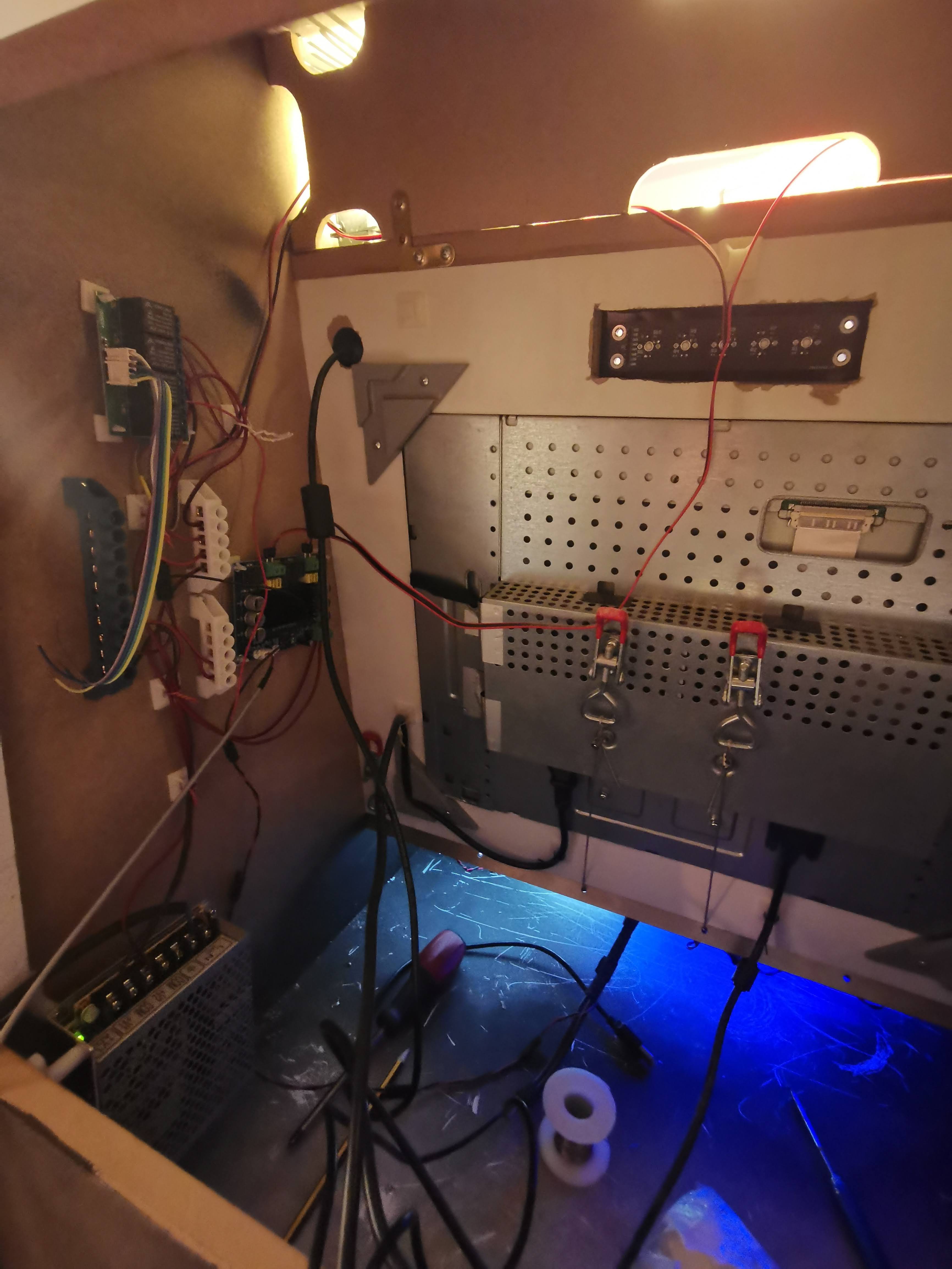
How it all works? Basically, front panel keypad controls latching relay module, 3 of available 4 channels, this is channel assignment:
- CH1 => Marquee LED backlight
- CH2 => Audio amplifier power
- CH3 => Controls backlight
- CH4 => FREE
Remaining 2 buttons on front panel keypad are connected directly to RPI GPIO port, and control the audio volume.
Power supply is distributed across all the components, including RPI and front panel keypad backlight.
Audio signals are also wired, directly to RPI 3.5mm audio connector, using custom made coax cable, including audio amplifier input and microphone mounted to marquee plate (To enable Google assistant support).
Next items on my check list are to create graphics, and replace RPI 3 with RPI 4 (This will enable Google assistant support and Wi-Fi connectivity)
Here are some photos
![]()
![]()
![]()
![]()
![]()
![]()
![]()
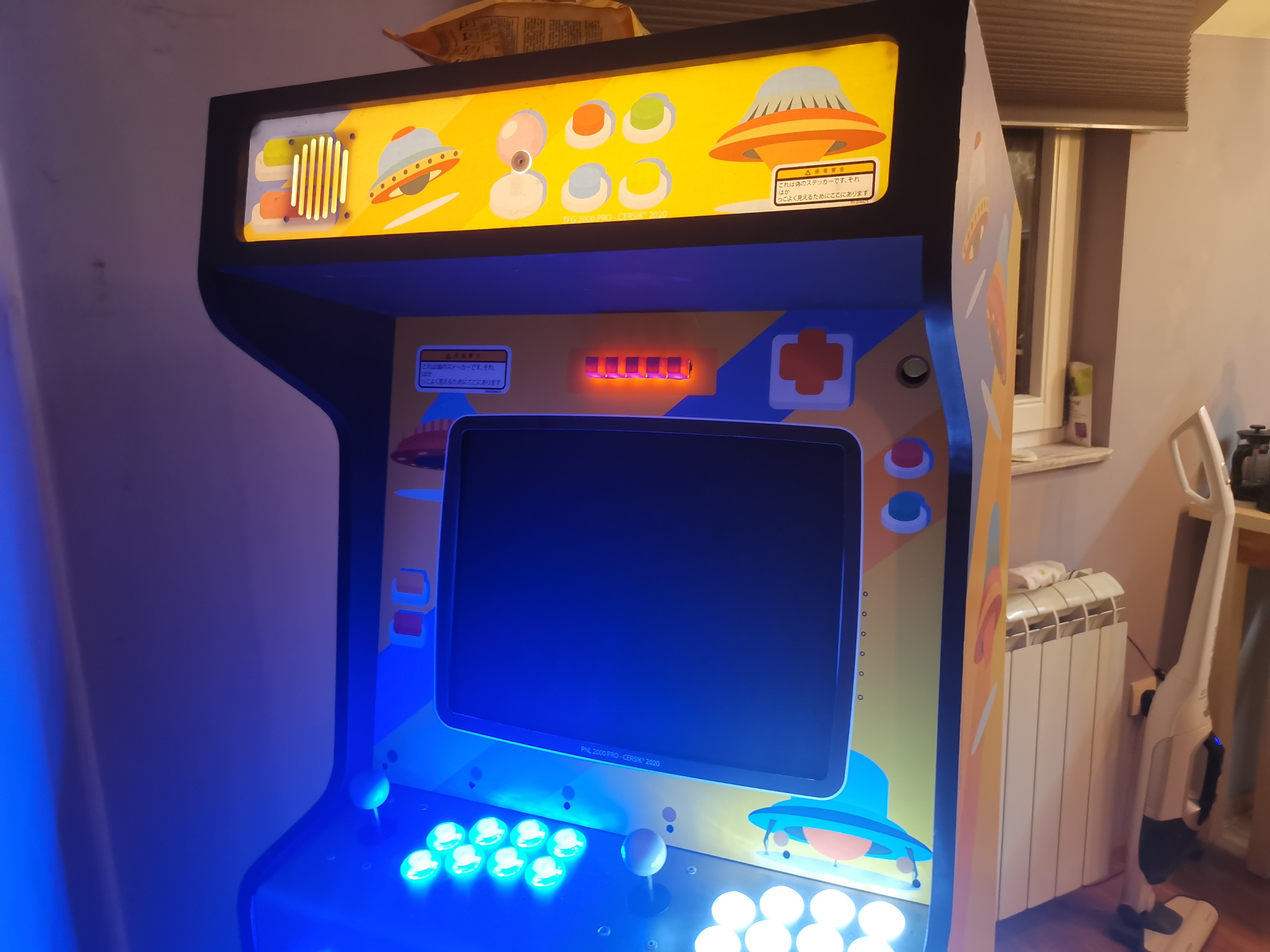
But mom, just one more game! [Arcade machine]
If you are an 80's kid, there is a great chance that you know what am I talking about, that's right, arcades!