David Tucker
-
Breathe-Right
03/01/2022 at 01:47 • 0 commentsSo my new laser module produces a lot more smoke, that makes sense since it is much more powerful. It is possible that I need to up my air assist game, although I did not see significant scorching on the few test cuts that I have done so far. What is clear from the smell in the garage is that it is time to revisit my air cleaner design. To start off lets look at what some commercial units achieve and how they are built. That will be our guide for trying to make a lower cost unit that is good enough for our needs.
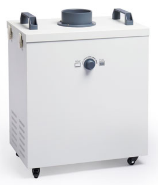
The Glowforge Air Filter is rated at around 350 m^3/h (200 CFM), and uses a 4" hose. It weighs in at around 22 kg ( 48 lb) and stands about 430 mm (17 in) tall and cost about $1,000. A glowforge is basically a 50w laser, so it is sized much larger than our needs, but it is a good upper bounds. The filter cartridg is a single monolithic unit that takes up most of the space in the unit and cost around $250. There are no details on this but presumably it is some combination of a HEPA filter and an activated charcoal filter.
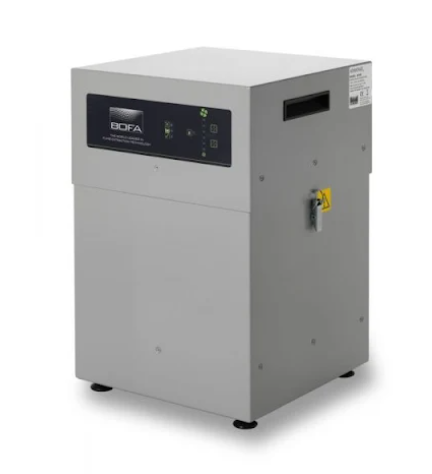
MatterHackers sells a BOFA AD 350 Fume Extractor for $2,500 that is suitable for even larger lasers. This uses similarly priced filters to Glowforge but they come in two parts with a lower cost $100 pre-filter and a $300 HEPA/Charcoal filter combo unit. It can generate 223 CFM, weights 77 lb and stands 23in tall. This is way overkill for our needs, but it is close to a professional grade filter.
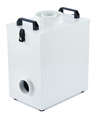
There are several lower cost filters available on amazon that are mostly geared towards solder fume extracting, but that may be big enough to get the job done. Example 1, Example 2, Example 3, Example 4. And there are a few that are geared more for laser cutters as well, like the ones from Omtech and Vervo. These are all a lot less expensive than the semi-pro filters above. However they are smaller, and the replacement filters are difficult to find and often cost as much as the whole unit.
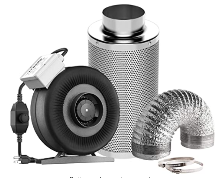
Finally we have carbon filters and exhaust fans from the indoor growing scene. These are quite inexpensive, but also lacking in many ways. For one they don't have an integrated housing, so you have to run the air backwards through the filter if you want to suck up smoke from a hose, or you have to build an enclosure for the filter. Another issue is that there is little or no pre-filter on these and they are mostly geared towards filtering out orders and not smoke particles so they really should be paired up with a proper HEPA filter. On the upside they are much better than a low cost soldering iron filter and they could act as a pre-filter for venting air outdoors that has less smell/smoke to it.
There is always the possibility of making your own filter from scratch. However that is tricky at best. Getting a fan and fabricating a case is not difficult but trying to come up with quality filters for a reasonable price is a challenge. It is easy to push the cost up into the price range of a proper unit.
-
2nd Pass
02/28/2022 at 00:44 • 0 comments![]()
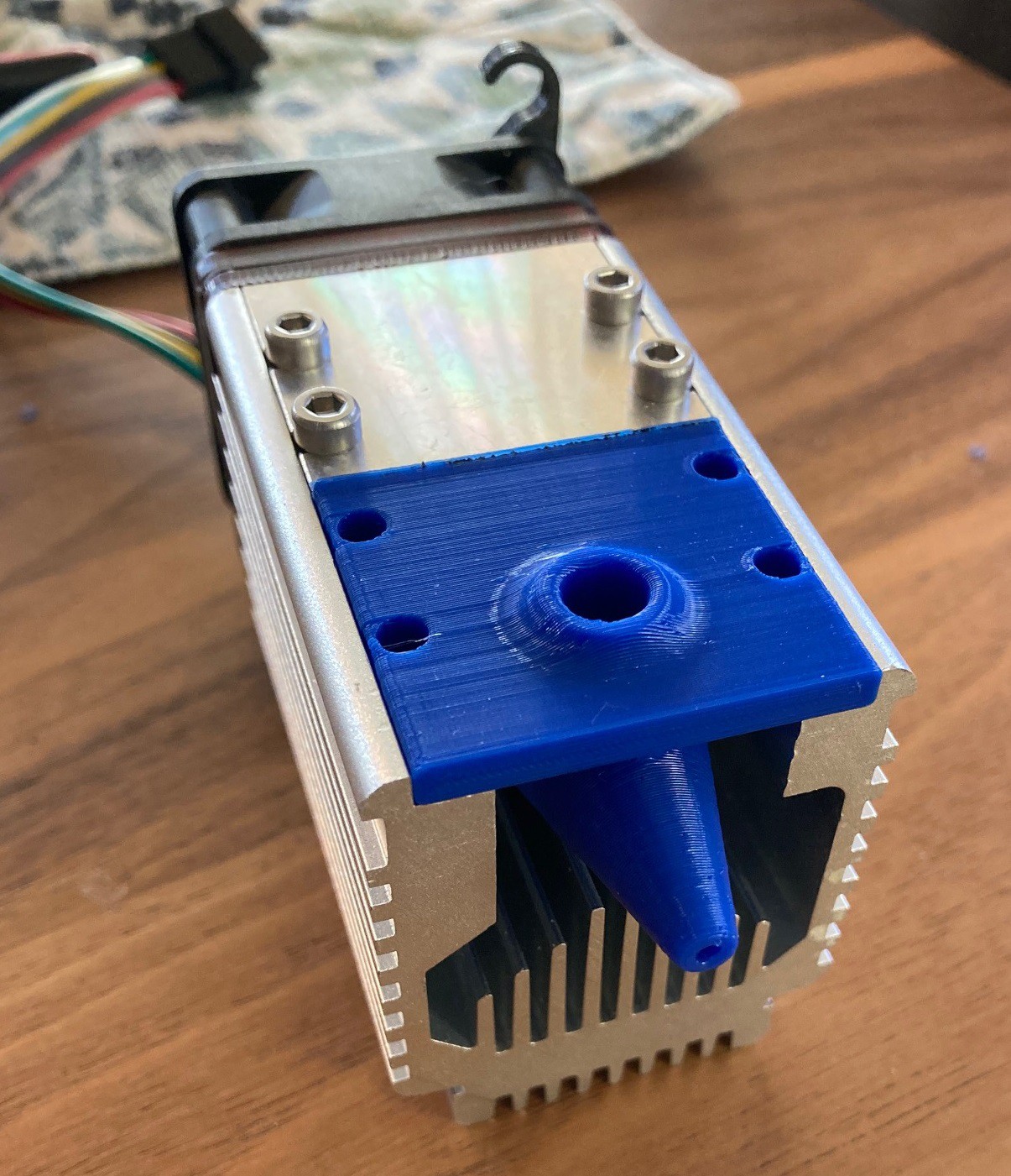
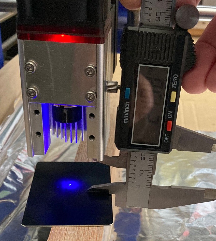
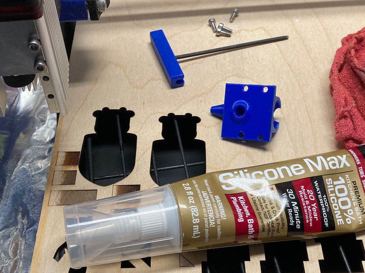
After a little trial and error I was able to make a new nozzle for my NEJE A40640 laser module. I put a bit of silicon on the end to seal it up and let it dry all morning. In the meantime I set the focus to 22 mm for both of my laser modules and made a focusing block that can be used at the base of the laser head or on the tip of the air assist as needed.
![]()
Once everything dried up I decided to run a few quick tests. I had a 12 mm piece of basswood that I decided to try cutting. At 80% power and 1,000 mm/min it cut 1.1 mm, 500 mm/min cut 3 mm, 250 mm/min cut 5.8mm and 125 mm/min cut 9mm, nearly all the way through the wood in one pass. I'm sure with a bit of tweaking I could have easily gotten all the way through.
I went ahead and tried engraving on an anodized aluminum card at 1,000 mm/min and 80% power. That worked ok, but my motors missed a few steps so repeating the cut caused a misalignment. I probably need to dial back on my acceleration values, I have them set high to try and get more speed out when engraving at 6,000 mm/min.
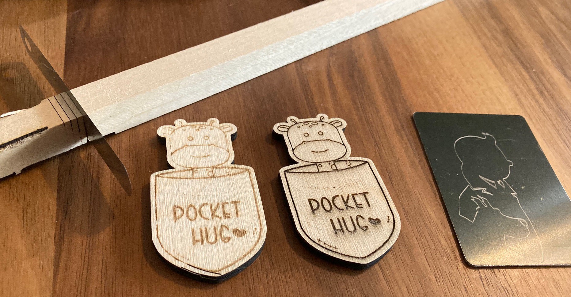
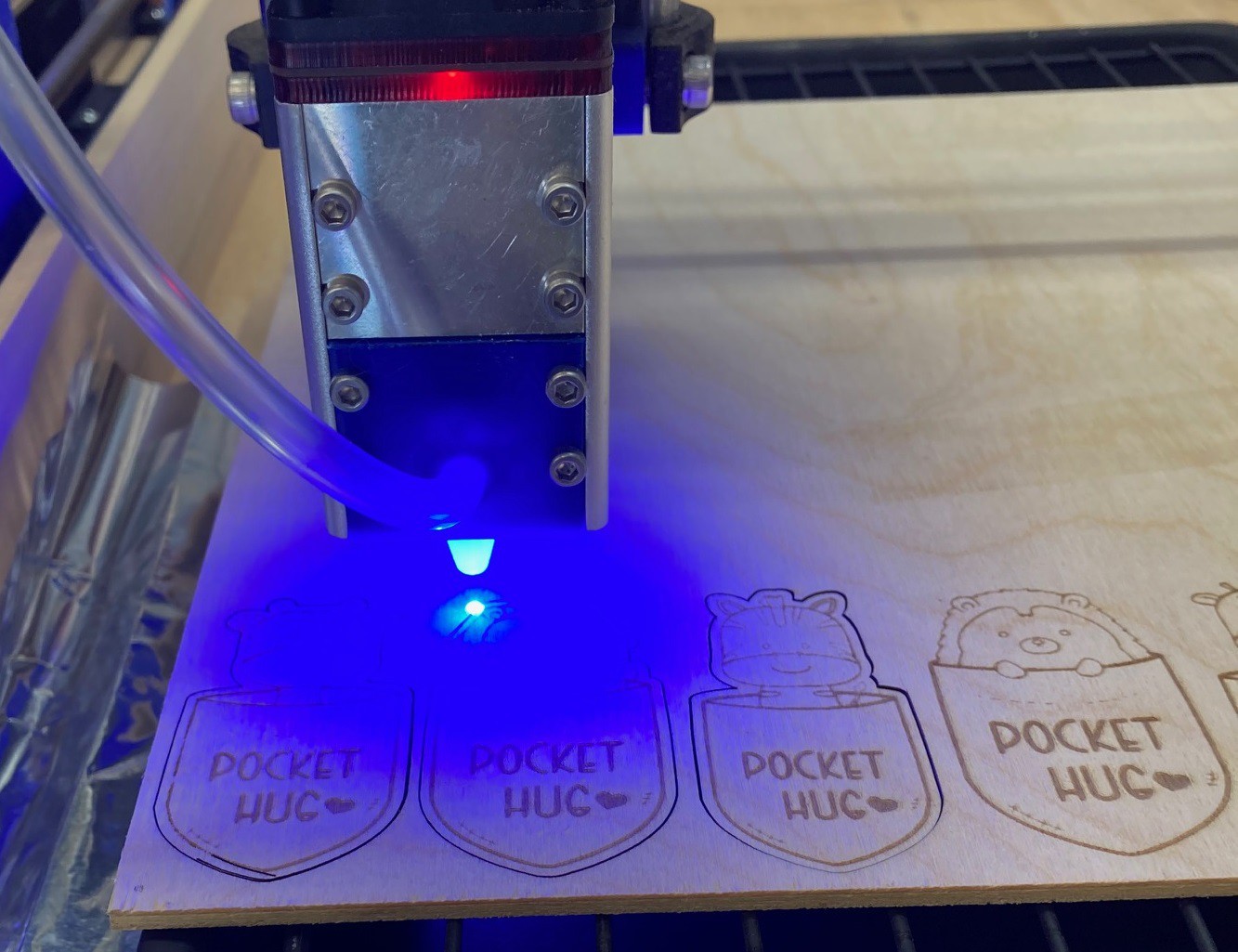
Finally I made a few quick test cuts then tried cutting out a pocket hug. Using relatively conservative values of 4,000 mm/min, 80% power and 0.15 mm line spacing to engrave and 200 mm/min, 80% power and 1 pass to cut I was able to cut one pocket hug out in 5 minutes. The estimator says I should be able to do a full sheet of 30 in 2.5 hours. I can probably shave a half hour off of that if I try to optimize the settings a bit more. In the picture above you can see my old attempt on the left with its washed out appearance and my new attempt on the right that is quite a bit darker and more defined as well.
I went ahead and put up my new air assist module on Thingiverse, however it probably needs more tweaking. In particular I should add a small lip to it to help contain the silicon better when trying to seal things up.
Anyway it is early days, but clearly this new laser module is working much better than the old one. I'm looking forward to really putting these head to head to see how much better it is. I did notice an odd behavior, when powered on but not firing the laser flashes periodically. Not enough to do any damage to the surface under it but it is strong enough to be noticeable even when wearing my glasses. I'm not sure if this is normal or not, or if it is some sort of byproduct of using too small of a power supply. I need to sort through my power supplies and see if I have a better one somewhere.
-
First Steps
02/27/2022 at 03:44 • 0 commentsI'm recovering from surgery so I'm moving a bit slow, but I managed to make an initial pass at looking into my new NEJE A40640 laser module.
![]()
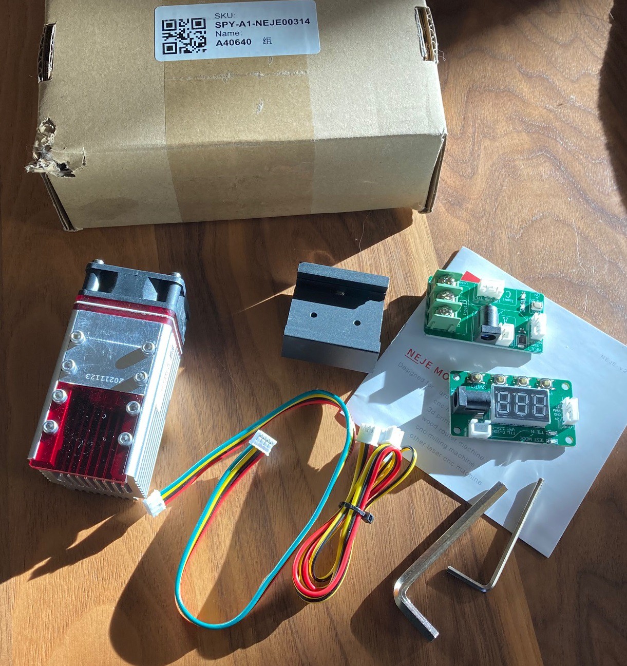
Here is what comes in the box. Don't mind the damage to the box, that was my dog's fault. Notice that there is no power supply or laser glasses with this module. Sadly they don't have an option to buy those parts.
The 30w module came with a 12v 3a power supply and the 40w module is suppose to use a 12v 4a supply. If you do the math then 12v * 3a is 36w, or just a bit shy of the 40w needed to run the laser at full power. I will try to dig up a proper 4a power supply, but not today, the 3a module should be enough for now.
![]()
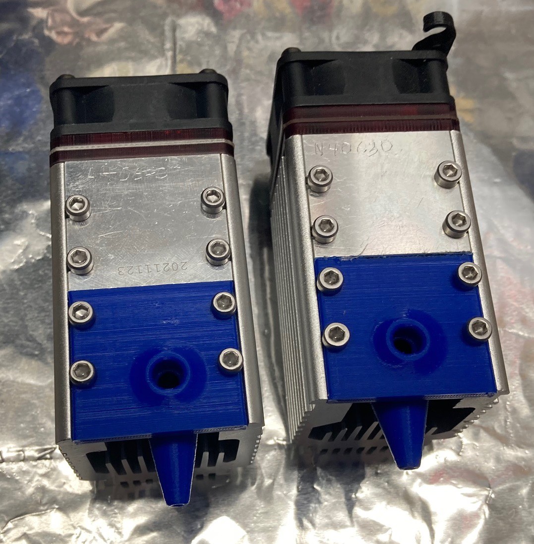
If you look at the modules, they are very close to each other but there are subtle differences. For starters the cooling fins on the 40w module are longer. Also the lens is offset to the right about 1.5 mm on the 40w module.
![]()
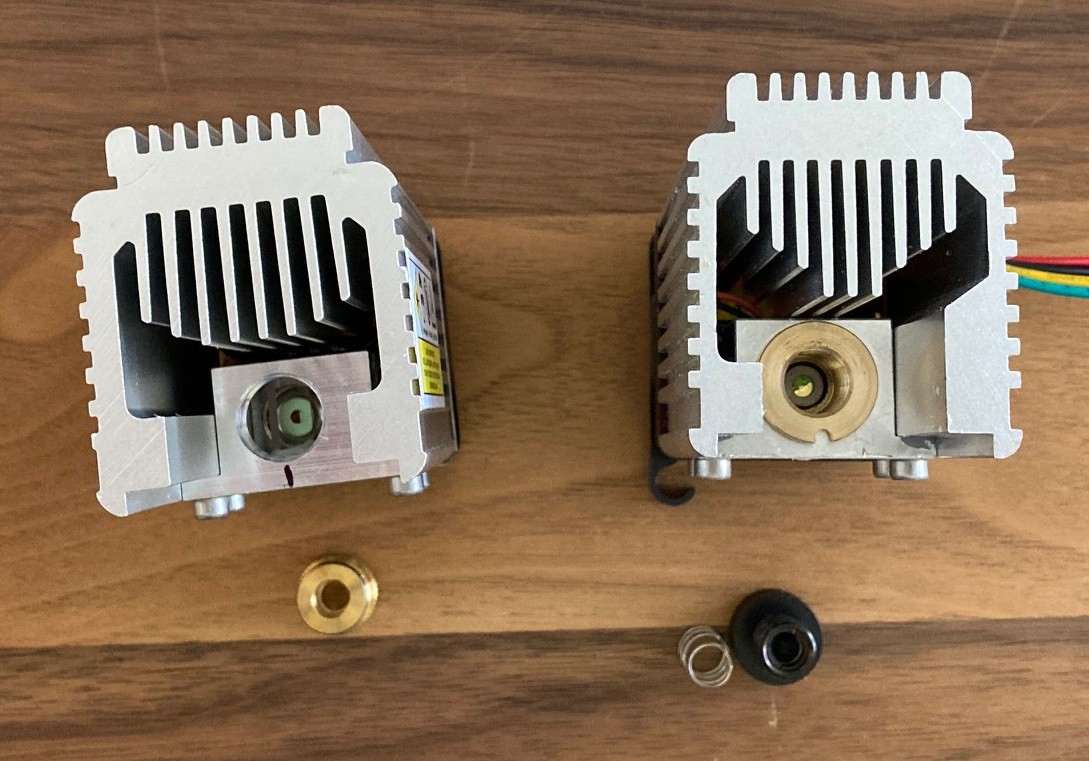
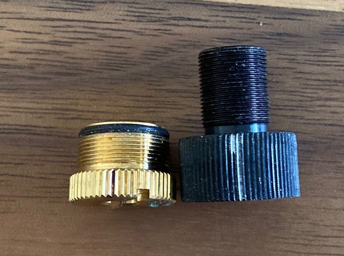
The lens is both smaller and shorter, only 13.5 mm in diameter and sticking 3.5 mm above the housing. If you screw the lens all the way in then it focuses about 22 mm below the bottom of the housing. Mine came unscrewed by one turn with a focus height around 17 mm (or was it 13?). Anyway I decided to set both of my modules to a 22 mm focus height, that will make them relatively even when comparing them together.
![]()
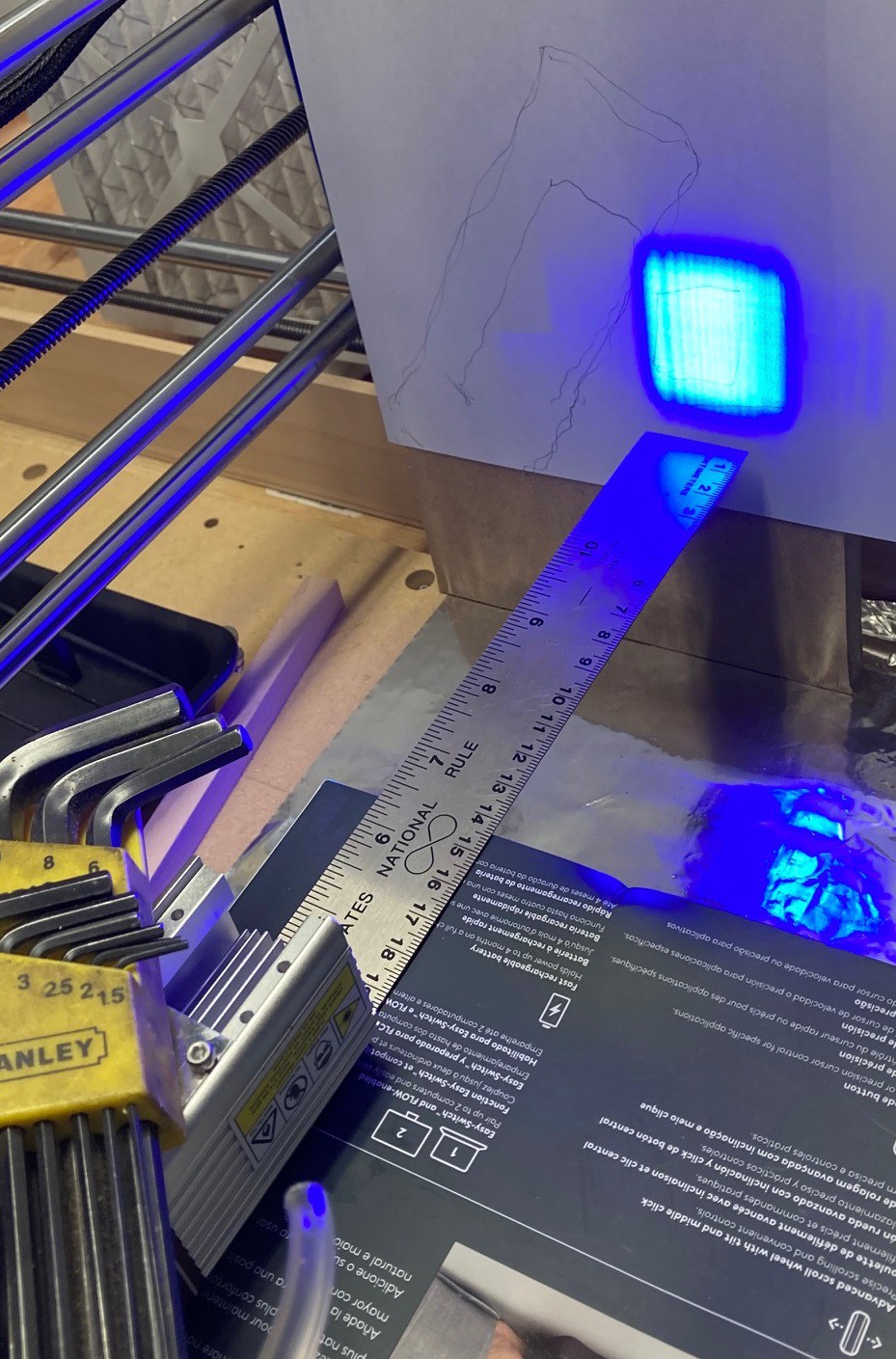
I pulled both lenses off and drew an outline of the resulting spot size at both 10 and 20 mm from the end of the housing. The NEJE N40630 came out to 9x3.5 mm at 10 mm distance and 16x5 mm at 20 mm distance. The end of the spot was cut off by the lens holder, so this is probably an underestimate. The NEJE A40640 module has a spot size of 3x2.5 mm at 10 mm and 5x4 mm at 20 mm. So it is true that the 40w module has a much slower divergence, that should result in a much smaller dot size, in theory.
I did not take a picture of it but it appeared that the 40w module had a larger spot size than the 30w module under the microscope. This is wildly subjective because the spot size changes dramatically as you increase the energy and the microscope can't view the spot head on, so it is possible that the microscope changed orientation between readings. There was also an interesting pattern of dots that appeared around the dot when it is in full focus. I don't know if this is a side effect of having light emitted in two orthogonal orientations or not.
Anyway I need to work up an air assist nozzle for this, then I can try to make a head to head comparison.
---
I found this new cad/cam program and wanted to drop a note on it. It is thin on documentation but it appears to have limited rotary support built in. Unfortunently it does not seem to have a trial demo, so there is no good way to verify that it would work for my rotary axis.
https://www.routcad.com/english/cad_cam/routcad25d.html
---
Here is an interesting way to generate dovetail connections with a laser. I cant remember if I mentioned it before or not, but I thought it was creative enough to be worth mentioning twice just in case.
https://hackaday.io/project/170065-laser-cut-dovetail-enclosures
-
Faster!
02/21/2022 at 17:58 • 0 commentsSo in my quest to engrave pocket hugs faster we already talked about upping the line step and how that has really only one proper setting. You can get quite a speedup with this, but you sacrifice a lot of quality in the process. The other way to speed things up is to bump up the speed the laser can scan at. This has the advantage of not significantly effecting quality (up to a point) but there are hard upper limits on this.
For starters if you double the speed you need to also double the engraving power to get the same power per mm. In the case of my N40630 5w module I'm already pushing the power about as far as I can. I could possibly engrave a bit faster, I will experiment with it, however I need my 4x stronger A40640 10w module to really benefit from this.
I experimented with bumping up the x axis velocity but quickly ran into a hard upper limit of 4,000 mm/min, at that rate I get a hard fault and the system stops running. My power supply is a 24 volt 3 amp unit, I have often wondered if this was strong enough. I'm using 4 stepper motors (5 with the rotary) and each is setup at around 1.5a power. In my mind that would require a 7.5 amp supply. However I found this article from Gecko Drive that says you need a power supply that is rated for 1/3 the amperage of the stepper. In that case my 3 amp supply is plenty since all steppers activated would only use 2.5 amps. They also give some interesting torque/power curves that suggest going with a higher voltage can in fact give you more torque at medium speeds, but no matter how strong the torque eventually falls off as speed increases.
I'm already running a 24v, and the drivers I'm using only go up to 28v so there is no real potential for bumping up the voltage. That leaves the amperage. To test out if I need a larger supply I pulled all the stepper motor drivers from my machine but the x axis. That way no power is being used by the drivers or motors and all the current is available just for the single x axis motor and driver. Repeating my tests I still had the same failure at 4,000 mm/min. So amperage is not the problem.
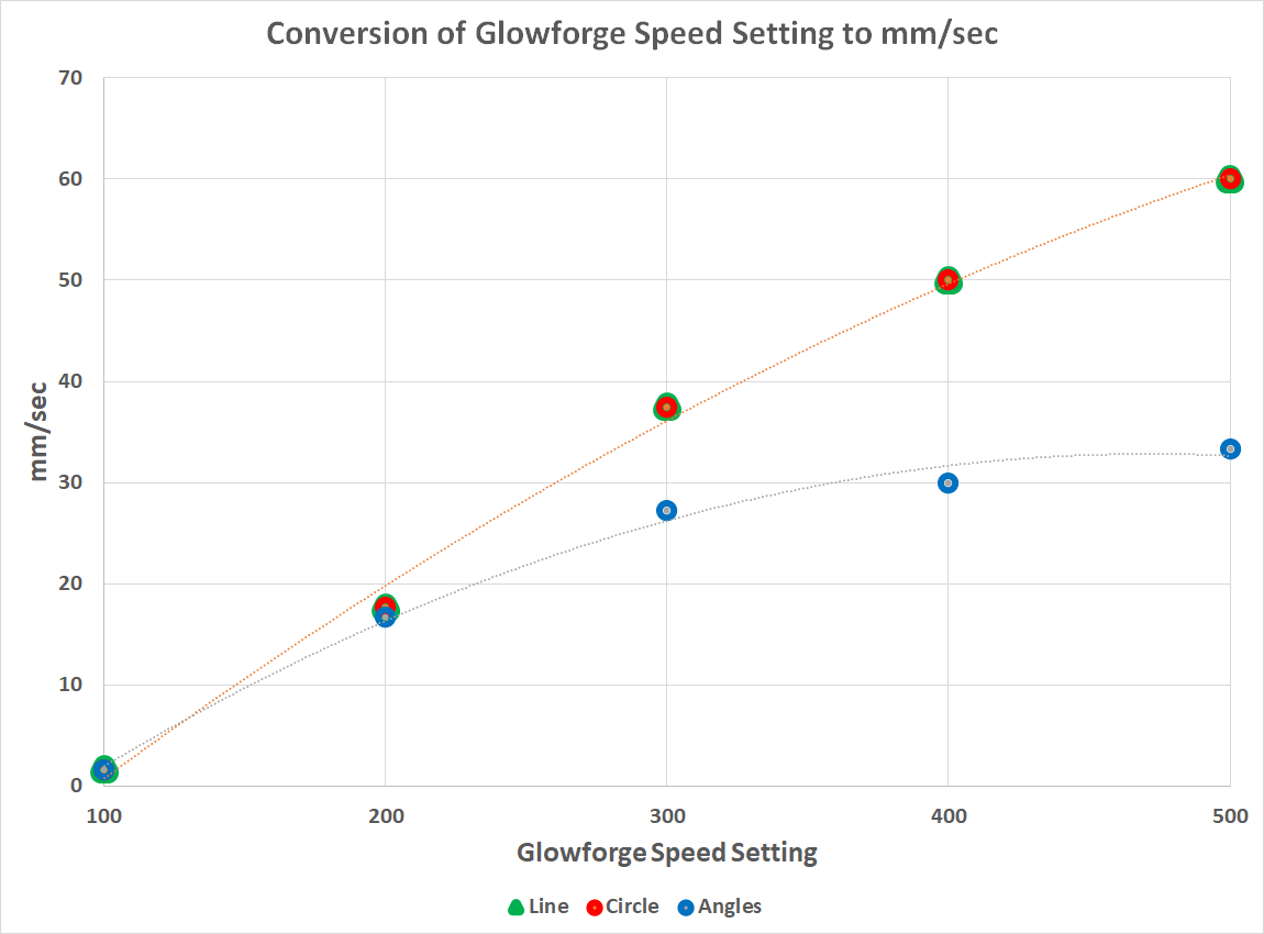
Another idea is that the arduino micro controller just cant keep up with number of steps required to run at these rates. My X axis takes 25 steps per mm, but with 16x micro stepping that is bumped up to 400 steps per mm. Running at 4,000 mm/min or 66 mm/sec that works out to around a 25 kHz step rate. The rumor is that an arduino could in theory run at 100 kHz step rate but things like interrupt handling may not be able to keep up at even 30 kHz. To test this theory out I pulled all the jumpers from my stepper, leaving it in 8 micro step mode. A quick tweak to the firmware to let it know about the change and I was able to run the X axis at speeds up to 7500 mm/min (125 mm/sec). So we found the culprit and I can in fact run my axis faster. However this comes with two catches. First the faster we go the more acceleration plays a role. That means that running at 6,000 mm/sec is not 2x as fast as running at 3,000 mm/sec over the full travel of the move because the start and finish of motion must begin at 0 and accelerate up to full speed. You can see this very clearly in this image from the Glowforge forum where they compare the actual speed of a 300 mm long cut using a straight line vs a series of 50 mm jogs in x and y. As they try to push the top speed up there is a point where acceleration overwhelms everything and there is little to no benefit to running faster.
![]()
We can play around with acceleration settings but eventually we will run into issues with lost steps when making small rapid motions, the same goes for jerk settings. Still it is something to play around with.
The other problem is that the stepper motors are not stable through there full range of speeds. Mine have an annoying resonance at around 3,500 mm/min. Running faster than that gives me smooth motion, but passing through that speed can result in a jarring sound and presumably unstable motion as well. This highlights a third closely related problem. These high speeds are fine for long linear motion but if we were trying to run at these speeds while tracing a complex shape we would most likely get oscillation when we have to rapidly change directions, like when cutting a square corner. And of course these speeds are not suitable at all for milling with a spindle. The motor torque is lowered at higher speeds and we would certainly miss steps, even if our spindle was capable of handling the speeds.
It would be nice to know what other machines manage to run at, that is a good way for us to estimate if we are in the ballpark or not. I did some digging around to find recommendations for various CO2 laser machines. I'm seeing numbers in the 100 mm/s to 300 mm/s range for the most part. That is 6,000 mm/min to 18,000 mm/min. Were never going to get up to 18,000 mm/min with this heavy laser diode on the end of a z axis but we could possibly hit the 6,000 mm/min range. Honestly I'm very suspicious of that 350 mm/s number, not that the machine can't be asked to run that fast, but that it has much impact on the real world speed, ie that the laser head can actually accelerate fast enough to achieve the speed it was asked to travel at.
I came across another note from a laser manufacturer that suggested that CO2 lasers can't really cycle faster than about once every millisecond. If your trying to hit a 0.1mm dot size that limits you to about 100 mm/sec for the top speed, 200 mm/sec if your going for a 0.2mm spot size (more realistic with a CO2 laser). You can of course go faster but your resolution will drop. And of course a CO2 laser has a larger dot size than a diode laser so they can run faster in the Y direction as well, but a diode laser will have an ability to engrave at a finer resolution.
Anyway I need to go back to the garage and actually try engraving at faster speeds to see if the laser can keep up and the motion is stable. I won't really be able to dig into this fully until I get my new laser module, but it has some serious potential to speed things up.
---
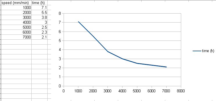
Here is a comparison of estimated run times (in hours) for engraving my project at 0.1 mm line spacing and varying the top speed from 1,000 mm/min to 7,000 mm/min using the current acceleration values for my machine. You can see that as we get above 4,000 mm/min the acceleration starts to overwhelm the process and the gains rapidly diminish with only a 30% decrease in time when going from 4,000 to (estimated) 8,000 mm/min. Note that doubling the acceleration only drops the run time by a small amount, there is more going on here than just the x axis travel.
---
I went ahead and pulled all the jumpers off of my x and y stepper motors, lowering there micro stepping from 16 to 8 (from 400 steps per mm to 200 steps per mm). This keeps my x and y axis using the same resolution. I left the Z at 400 micro steps but it probably could be lowered as well.
While I was testing everything out I noticed that a few of my clamps and backlash nuts on my lead screws had loosened up a bit. A quick bit of tuning things up and I was able to get rid of a lot of the resonance at 3,500 mm/min speeds.
In the end after some playing around I settled on a max speed of 6,000 mm/min in x and y with an acceleration of 200 mm/sec^2. This seems stable and yet does not over exert the machine. That is only good for doing a scan over a large area. Trying to do a vector cut at 2,000 mm/min caused some stability issues when doing rapid changes in direction. It is possible that I could tune this out by lowering acceleration, but that reduces the benefits of the higher speeds. For now I will leave it like this and just manually limit the speed of vector cuts to 1,000 mm/min or lower.
My birthday is on Wednesday, I cant wait to try out my new laser module and see what it really can do.
-
Refocus
02/21/2022 at 00:32 • 0 commentsSo a few posts ago I messed around with making the focus much higher. This is more in line with the current recomendations from NEJE and it allows me to have more clearance when trying to use my laser with the rotary axis. Using a 6mm focus height brings the laser housing very close to the jaws of my rotary chuck.
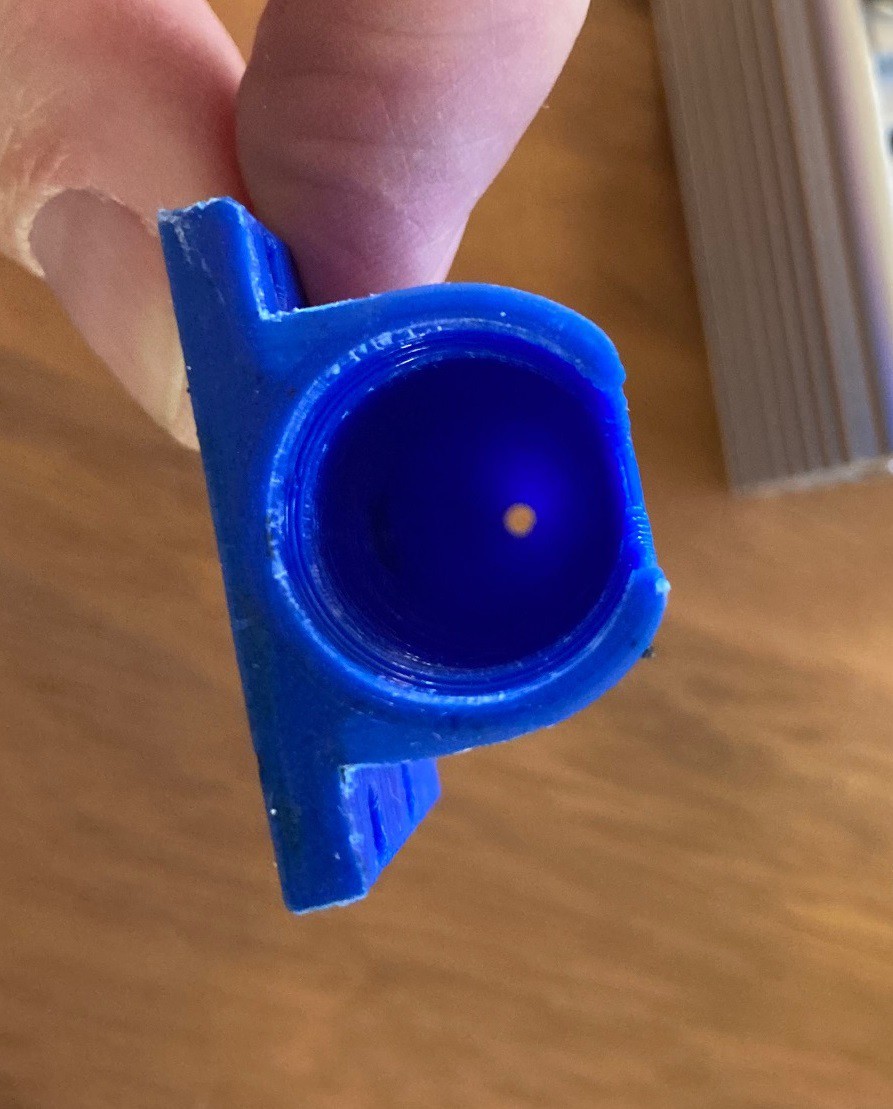
However going to this higher focus height caused interference with my old air assist nozzle. The bottom of the nozzle was being hit by the laser and it caused some melting of the nozzle as well as a loss of power from a reduced focus spot size. This lead me to redesign my air assist nozzle.
![]()
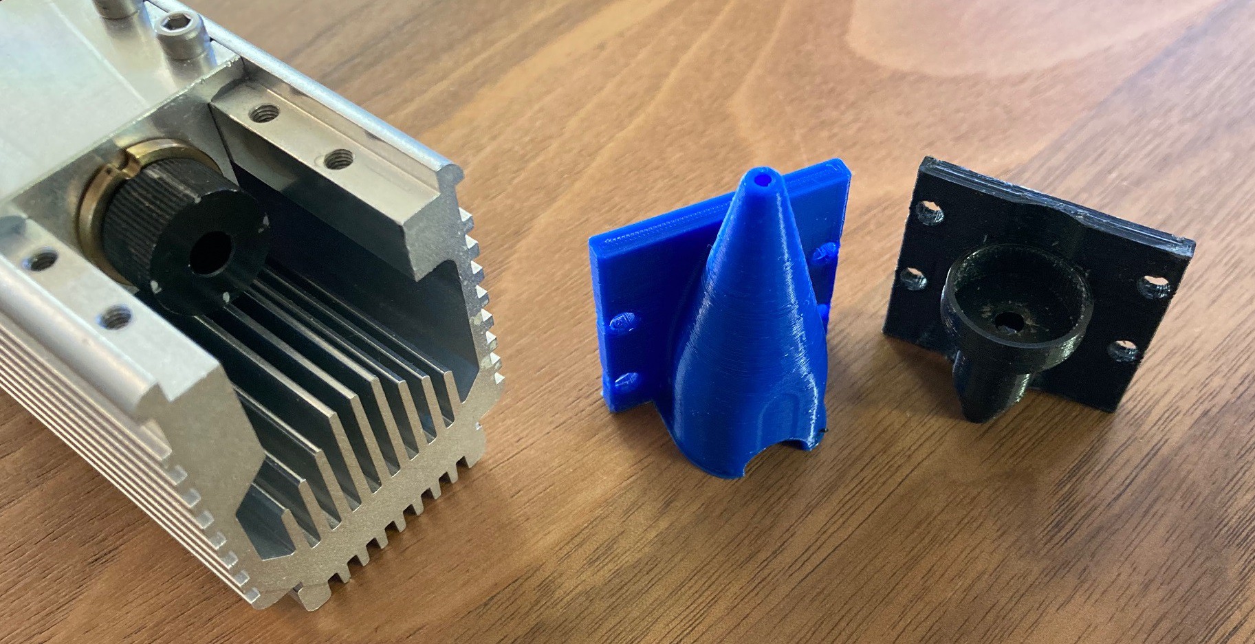
My old nozzle was designed to be printed tip down with no supports. It worked ok, although there was some issues with elephants foot on the nozzle opening. The new nozzle carefully extends the part that covers the lens all the way to the top so it can be printed upside down without any supports.
![]()
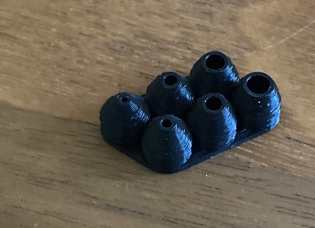
Since I changed how the nozzle was printed, I went ahead and made a new nozzle hole size test. This time I made it as a single monolithic piece that goes from 1.5 mm to 3.5 mm diameter holes. Again after lots of back and forth testing the 2mm sized hole appears to be optimal both with my aquarium fish pump and with 15 psi from my pancake compressor.
![]()
I designed this to have a 22 mm focus height from the base of the housing to the top of the work surface. The nozzle itself is 12 mm tall leaving 10 mm from the tip of the nozzle to the top of the cutting surface. This is roughly in line with what NEJE recommends.
![]()
The nozzle has a close interference fit with the end of the lens. However there is enough of a gap that a significant amount of air flows around the lens.
![]()
To work around this I applied a small amount of silicon all around the inside of the nozzle with my finger, then pressed the nozzle on over the lens and let it dry overnight. This has formed a solid coupling and since there is no lip inside the housing the extra silicon did not get forced back inside the lens opening, a problem I had with my last nozzle.
![]()
I have uploaded all my laser related models to Thingiverse if you want to grab any of them. This includes the air assist nozzle and a housing for the NEJE display/controller board.
---
Here are focus dimensions taken from various NEJE images posted to there website for several different laser modules. You can see that even there own numbers are not very consistent. That is why I picked an average value of 22 mm focal height from the base of the housing.
n30820
- 12(32) mm focus to top of lens
- 15(35) mm to base of wood
- 8 mm max cut
- 5 mm below top of material
- 2(27) mm to top of materialN40630
- 17(37) mm focus from base of laser
- 20(40) mm to base of wood
- 8 mm max cut
- 5 mm below top of material
- 12(32) mm to top of materialA40630
- 17(37) mm focus from base of laser
- 25(45) mm to base of wood
- 18 mm max cut
- 10 mm below top of material
- 7(27) mm to top of materialA40640
- 22(42) mm focus from base of laser
- 30(50) mm to base of wood
- 18 mm max cut
- 10 mm below top of material
- 12(32) mm to top of material -
Pocket Hugs
02/20/2022 at 21:03 • 0 comments![]()
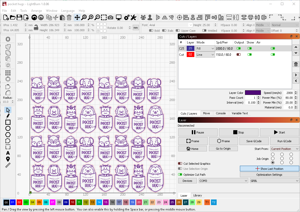
My wife saw these pocket hugs for sale online and asked me to work out how to make a set for her to give away to here students. I looked around and found this Etsy seller with some svg files that looked cute. I imported these into LightBurn and used the offset shape command to create a separate cut outline around the images and arranged them in a grid that would just fit on a 12"x12"x1/8" sheet of Baltic birch plywood.
![]()
This was a big project for my little NEJE N40630 laser so I have been spending some time experimenting with different ways to optimize the cut.
My initial attempt was:
Engrave: 7.0 hours, 1000 mm/min speed, 50% power, 0.1 mm line interval
Cut: 2.0 hours, 150 mm/min speed, 80% power, 3 passes
Total: 9.0 hoursThis looked good when I ran a test cut, but it was really slow. I tried bumping the speed up to 2,000 mm/min and bumped up the power to 80%, that cut the engrave time down to 5.5 hours. Why not to 3.5 hours? It must be down to acceleration limits and y moves. This is better, but it is still a 7.5 hour job.
So I started digging around to see what I could do to make this run faster. One idea is to bump up the line interval so we are making fewer passes. I jumped right to 0.2 mm and found that the quality was terrible. I then tried raising the focus height up 5 mm to make a larger spot size to compensate, but that cut the power down low enough that the image was completely washed out. So I decided it was time to start doing some actual research rather than just taking shots in the dark.
LightBurn has a tutorial on how to properly set the DPI/line interval, basically there is only one right number and getting it wrong will cause the contrast to be messed up or you to loose resolution. I also dug around and found this forum post and video talking about a way to actually test. So I sat down and tried to test it out myself. I drew a 20 mm long line in light burn then used the 'perforation' option to segment the line in 0.1 mm dots with 0.1 mm, 0.15 mm and 0.2 mm gaps between the spots then ran some test. I also drew a small box and filled it in with the same intervals. Using the microscope I could see that 0.15 mm almost worked but 0.1 mm looked better. Still it was close enough, and the speed savings great enough that I attempted to cut some tokens out at 0.15 mm line spacing.
This brings the time way down:
Engrave: 3.5 hours, 2000 mm/min speed, 80% power, 0.15mm line interval
Cut: 2.0 hours, 150 mm/min speed, 80% power, 3 passes
Total: 5.5 hoursHowever the small details are lost and the fill lines are light.
![]()
It worked, but not great, the speed is better but you loose detail and it was hard to capture the small lines in the source image. I also struggled to get the same depth of burn. However in a pinch I would be tempted to fall back to this if I really needed to speed things up.
My hope is that my new A40640 module will allow me to push things faster and I can cut this down from an all day project to something that can be completed in a few hours. I have some experiments in the works on pushing things faster, I will write about those later once I get some hard data.
-
Find processes holding a file open
02/13/2022 at 04:10 • 0 commentsThis is a little off topic, but I spent way too much time trying to work this out and need somewhere to post it. I wanted to get a list of other processes that where holding open a file (or other object) that I also was holding open. This is the core of what SysInternals Handle application is doing.
There is some limited example code out there that shows you how to do this using only the path to the file in question. However these example projects don't work if the process holding open the handle are running at an elevated privilege level to your own application. This is because they rely on you cloning a handle owned by the other process, something you can't do for security reasons if you don't have the right permissions.
In my case I already have a handle opened to the file of interest. My inspiration is to search through all available handles on the computer to find my own handle and then use that to look up the unique object pointer in order to compare against other handles to see if they also are pointing to the same object. That way we can identify the handle without needing to clone a pointer and we only need to use a much lower risk call to work out the process name. This should work with any resource and any process running at any level of elevation. It is also much faster since we don't have to mess with every process on the computer.
Note that this only cares about handles, it does not mater what resource you have opened. It can be used to find who else has a file opened, but it works just as well with loaded dll's or other resources that could have a windows handle.
// SYSTEM_INFORMATION_CLASS from winternl.h #define SystemExtendedHandleInformation 64 //0x40 #define STATUS_INFO_LENGTH_MISMATCH 0xc0000004 typedef struct _SYSTEM_HANDLE_TABLE_ENTRY_INFO_EX { void *Object; ULONG_PTR UniqueProcessId; ULONG_PTR HandleValue; ULONG GrantedAccess; USHORT CreatorBackTraceIndex; USHORT ObjectTypeIndex; ULONG HandleAttributes; ULONG Reserved; } SYSTEM_HANDLE_TABLE_ENTRY_INFO_EX; typedef struct _SYSTEM_HANDLE_INFORMATION_EX { ULONG_PTR NumberOfHandles; ULONG_PTR Reserved; SYSTEM_HANDLE_TABLE_ENTRY_INFO_EX Handles[1]; } SYSTEM_HANDLE_INFORMATION_EX; typedef NTSTATUS (NTAPI *_NtQuerySystemInformation)( ULONG SystemInformationClass, PVOID SystemInformation, ULONG SystemInformationLength, PULONG ReturnLength ); _NtQuerySystemInformation NtQuerySystemInformation = (_NtQuerySystemInformation)GetProcAddress(GetModuleHandleA("ntdll.dll"), "NtQuerySystemInformation"); // Print out every process that has the resource opened corresponding to the passed in handle // that is get a list of applications that have a speciffic file opened. void GetProcessNameFromHandle(const HANDLE h) { // is handle valid if(h != 0) { NTSTATUS status = -1; // take a wild guess at the size of the data, there are likely hundreds of thousands of handles opened ULONG SystemInfoLength = 5242880; // 5 megs SYSTEM_HANDLE_INFORMATION_EX *SystemHandleInfo = (SYSTEM_HANDLE_INFORMATION_EX*)new char[SystemInfoLength]; // try to grab the data // we can't use the ReturnLength parameter to work out this size, it always returns a small number that is incorrect. while(SystemHandleInfo && (status = NtQuerySystemInformation(SystemExtendedHandleInformation, SystemHandleInfo, SystemInfoLength, NULL)) == STATUS_INFO_LENGTH_MISMATCH) { // if our guess was too small then keep trying larger blocks delete [] SystemHandleInfo; SystemInfoLength *= 2; // double the memory over the last try SystemHandleInfo = (SYSTEM_HANDLE_INFORMATION_EX*)new char[SystemInfoLength]; } // did we grab data? if(SystemHandleInfo && NT_SUCCESS(status)) { // work out our own process id ULONG CurrentProcessId = GetCurrentProcessId(); // search twice through the data, once to find our own handle to the files // and again to find any other processes with handles to the files int hIndex = -1; for(unsigned int i = 0; i < SystemHandleInfo->NumberOfHandles; i++) { // if our own process if (CurrentProcessId == SystemHandleInfo->Handles[i].UniqueProcessId) { // did we find the handle? if(SystemHandleInfo->Handles[i].HandleValue == (ULONG_PTR)h) { hIndex = i; break; // no need to keep looking } } } // did we find our own handle to the file? if(hIndex >= 0) { // search again for other records matching our found files for(unsigned int i = 0; i < SystemHandleInfo->NumberOfHandles; i++) { // don't bother looking at our own process if (CurrentProcessId != SystemHandleInfo->Handles[i].UniqueProcessId) { // if were looking at the same object, this works because the object pointer is unique across all processes if(SystemHandleInfo->Handles[i].Object == SystemHandleInfo->Handles[hIndex].Object) { // then work out the name of the process that has the handle open // we use PROCESS_QUERY_LIMITED_INFORMATION so we can open the handle even if the process has elevated priveleges char processName[MAX_PATH]; HANDLE hProcess = OpenProcess(PROCESS_QUERY_LIMITED_INFORMATION, FALSE, (DWORD)SystemHandleInfo->Handles[i].UniqueProcessId); if(hProcess) { DWORD tMaxLen = MAX_PATH; if(QueryFullProcessImageNameA(hProcess, 0, processName, &tMaxLen)) { printf("%s\n", processName); } CloseHandle(hProcess); } } } } } } if(SystemHandleInfo != NULL) delete [] SystemHandleInfo; } } -
Speed vs Power
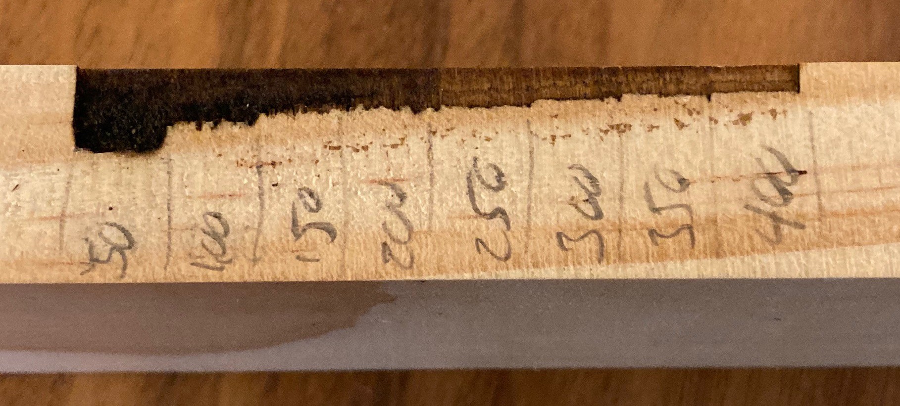
02/11/2022 at 04:15 • 0 commentsI wrote a new test to cut a series of lines on top of each other in the x direction while varying either the speed or power across the line. I used a 0.05 mm stepover in the y direction between lines, that works out to the equivalent of 2-4 passes over the same spot. That was too much of a stepover, I probably should be using 0.025 mm stepover since my kerf width is less than 0.1 mm
![]()
Here is the result when varying the speed from 50 to 400 mm/min in steps of 50 at 80% power with my NEJE N40630 module. You can see there is a lot of damage to the material when going at 50 mm/min, it is not super clear in this image but there is a lot of scorching on the wall of the cut. Things look much better at 100 mm/min and above about 200 mm/min the walls show very little damage at all.
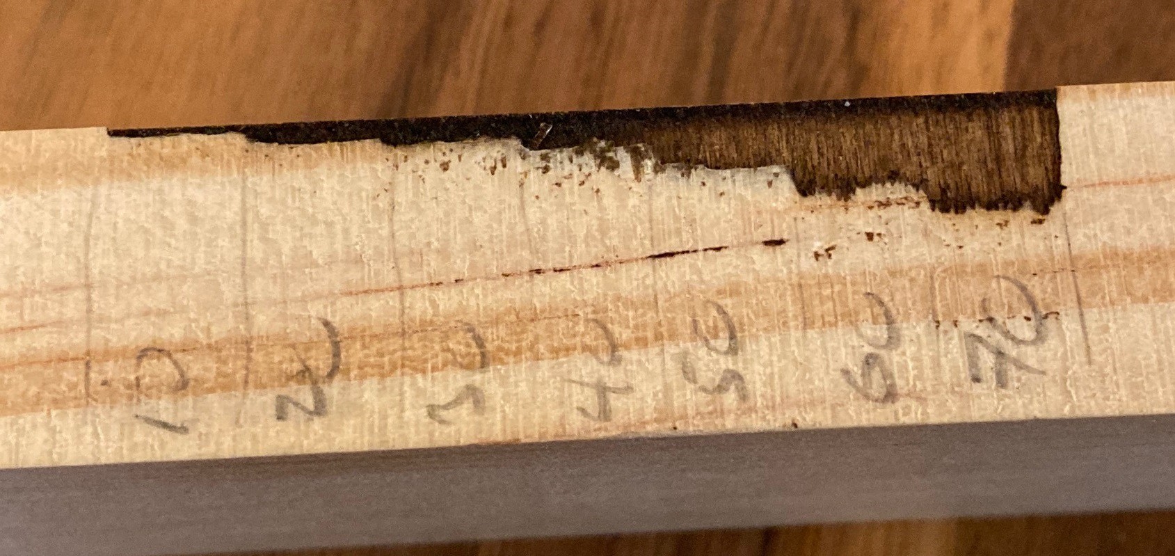
![]()
And here is another test where I varied the power from 10% to 70% in steps of 10 at 100 mm/min. At around 50% power we start to see significant damage to the walls, although not nearly as bad as 50 mm/min at 80% power. A bug in my test code prevented this from going to 80% so we can't directly compare it to the last test. However at 70% power and 100 mm/min we are cutting deeper than the test at 80% power and 100 mm/min on the previous test. I suspect this is because the wood is not very uniform and I hit a softer spot.
If you look close at both pictures when the cut is the deepest you will see that there is a lot of variability to the cut depth. I measure it at around a mm of variation.
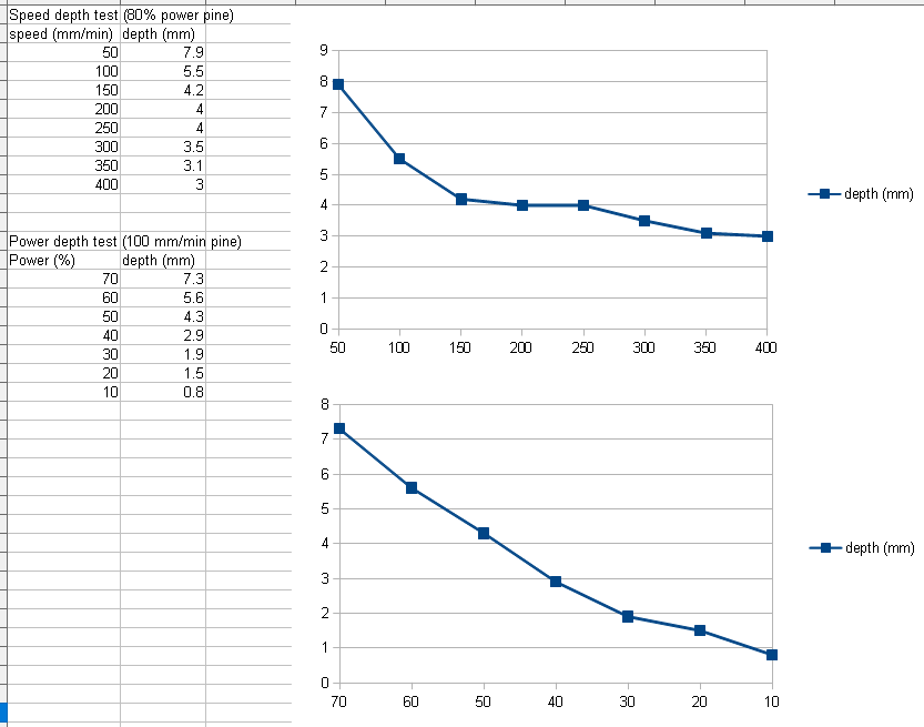
![]()
I roughly measured the depth of each cut, these are probably accurate to within a mm, and then plotted out both in the above graphs. You can see that there is a clear logarithmic (1/x) behavior when we vary the speed while varying the power has a much more linear behavior. It was difficult to measure the shallow cuts with any accuracy, this is probably more linear than it appears.
If you combine all this data together with the images above you can see that while we can cut material up to 7-8 mm deep with enough passes and a very slow speed we are probably better off running at 150 mm/min or faster and sticking to depths less than 4 mm to both optimize cut times and to get the best surface finish.
![]()
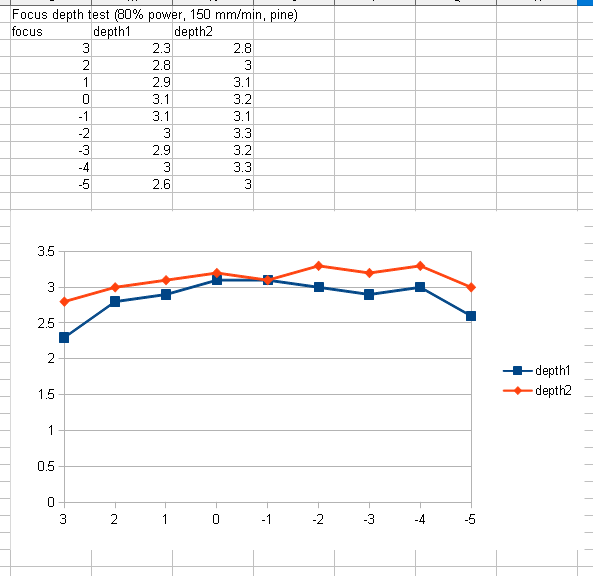
Finally I ran another focus test where I started 3 mm higher than focusing the laser on the surface and lowered it on each line to 5 mm below the surface. I first used my new microscope to verify that the laser spot was in fact focused on the surface of the pine. I measured the cut depth twice using my usual trick with a feeler gauge and calipers. The results came out almost 0.3 mm deeper the second time. My theory is that there is a lot of ash at the bottom of the cut and each time I insert the feeler gauge it cuts deeper into the ash. This variance makes it very difficult to measure anything to better than 1 mm accuracy.
Anyway looking at this I don't see much variance in the cut depth. I have a feeling I need a much wider range to truly see the effects on height. It looks like getting focus dialed in to within 6 mm (on this piece of pine) gets you a reasonable depth of cut. Next I need to do a ramp test and work out if it is resulting in a value that focuses at the surface of the material or deeper. Finally I can try re-running my previous test to see if lowering the laser between cuts has any value. It is very possible that in the past I was focusing well below the surface on accident and lowering the laser further had a negative impact on the depth of cut.
---
If you look closely at the cuts above you can see a definite darkening of the burn where the darker tree rings are. That throws any results off just a bit. I'm still working to find a more optimal material to run these tests on. I would like something that is extremely uniform in every regard. I may start looking at cutting foam or plastics that are more uniform.
-
Math
02/05/2022 at 23:41 • 0 comments
So I have been going over research papers trying to work out the relationship between laser power and cutting speed. I came across a few papers that seem to fit the bill.if you dig into the papers and do a little simplification you get an equation like this that tells you approximately how deep a cut will be.
This says that increasing the laser power or the number of passes should increase the cut depth in a linear way. While increasing the velocity of the laser head or increasing the size of the laser spot will result in a decrease in cutting depth at a logarithmic rate. This falls out of the math easily enough, if we plug 1 in for all values but power then we end up with depth = x, while if we plug in 1 for all values but velocity we end up with depth=1/x. This equation is missing some constants that dial it in for each material type, so keep in mind this is an approximation.
We can pull out a part of this equation and call it energy per unit length or energy = power/velocity. For any given material type it can only take so much energy before being permanently damaged (burning) and that defines the optimal ratio between power and velocity. Say the material can only take 1 unit of energy before burning, then we can choose to run 1 unit of power at one unit of velocity, or 10 units of power at 10 units of velocity resulting in a faster cut, but we can't get any more depth out of the laser than this. We can try to run more passes to get more depth without adding more energy, but only up to a point.
Another interesting point here is that it is the focus spot size that dictates the ultimate depth of cut. If the spot size grew to 4x its smallest size then we would only have 25% of the energy to cut material. The way the laser focus spot works we end up with a 'waist' where the laser spot size is relatively unchanged, but outside of that area the laser light diverges rapidly. This means that as our cut depth increases past the depth of this waste we start to loose cutting power and eventually it gets to the point where no amount of extra passes, reduction in speed or energy can overcome the loss. Basically any laser, no matter how strong, will ultimately have a maximum depth of cut.
![]()
According to these equations there should be no difference between laser power or passes. That is a laser with power of 1 running 2 passes should be equivalent to a laser with a power of 2 running 1 pass. Also there is an inverse relationship between speed and power, so if you want to run at 2x the speed you need 2x the power or 2x the passes to cut the same depth. In practice there are small differences in each material that make power and passes not fully equivalent, and the above limitations are still in place and you can't keep cutting deeper and deeper by just increasing power or reducing speed. But as a rule if someone says they cut at high speed for many passes you can reduce the speed and passes at the same rate and get an equivalent cut
---
Here are some of the papers I used to derive this.
https://citeseerx.ist.psu.edu/viewdoc/download?doi=10.1.1.461.8005&rep=rep1&type=pdf
https://www.fpl.fs.fed.us/documnts/fplrp/fplrp250.pdf
http://alumni.media.mit.edu/~yarin/laser/physics.html
https://makezine.com/2019/03/04/a-deep-dive-into-laser-cutter-speed-and-power/
https://www.sciencedirect.com/topics/engineering/laser-power-density
---
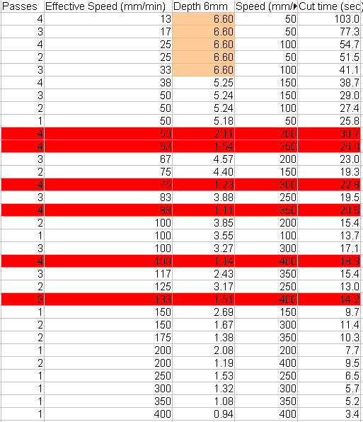
Edit, I went back to some of my old data and calculated an effective speed that is just speed/passes, then I sorted the data by effective speed and then by depth. The data is below, you can see the red columns are way out of range. Most of these are 4 passes, resulting in a much shallower cut than the 3 passes. I have no explanation for this, but it is interesting to see strong evidence that 4 passes does result in a shallower cut (at least a cut that is full of ash or something). Also the first 5 entries are actually deeper than the material (over 6 mm deep) and there values are basically useless. Looking at the data, 4 passes at 200 mm/min results in a depth of only 2.11 mm while 3 passes at 200 mm/min has a depth of 4.57 mm, over twice the cut depth. This is crazy, but I keep running into it.
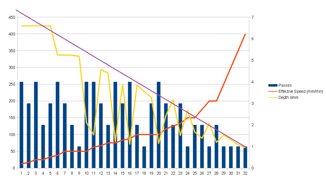
Plotting the data you can see what appears to be a linear relationship between cut depth and speed (all using 80% power). You need to squint a bit to rule out the 4 pass points that fall out of the norm. And the first 5 points are not worth much as well. What is interesting is that as the cut depth drops (the speed increases) we start to see 3 pass cuts that are not as deep as 1 pass cuts and so on, but the discrepancy is not nearly as dramatic. I drew the purple line in by hand to give you a rough idea of what a truly linear result would look like.
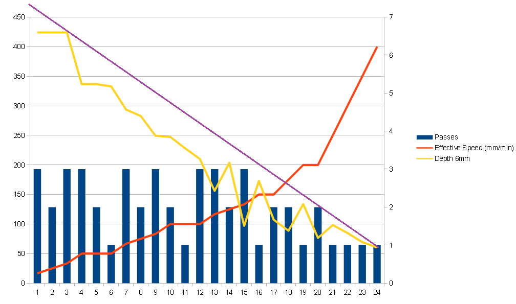
Here is the same data with all 4 pass data removed, you can see that it is a lot more linear but there is starting to be some discrepancy with the three and two pass data as the effective speeds increase.
-
Small notes
02/03/2022 at 00:57 • 0 commentsSo I took a moment to play with my new usb microscope and thought I would post a few notes on it.
First off this claimed to be a HD camera but really it only has 640x480 resolution. With that said, this is enough to get the job done. And chances are all the other low cost units on amazon and ebay have similar resolutions. This one came with two holders, neither are worth anything. You can easily hold the module by hand while adjusting focus, a holder is not needed.
I tried using my yellow filter to block most of the blue laser light. I was hoping this would allow us to see the spot in more detail rather than just being blown out in the camera. However it was a dud, it had no benefit on the light. That is ok, I really picked up a variety pack of acrylic sheets. I have always heard that blue lasers can't do anything with these, but I wanted to prove it for myself in a future experiment.
I had also picked up a pack of anodized aluminum black sample sheets to use as focus targets. They work great, there is a lot less back scatter and the surface is smooth so it is easy to focus on consistently. The spot is difficult to see with your eye (when wearing safety glasses) so you don't want to use these without a microscope. You could do just as well by painting a smooth piece of plastic or metal matt black. I really picked these up to experiment with lasering off the anodizing so I'm glad I got them.
The microscope works great, you can get the focus dialed in to within a mm or two, however it is difficult to get it dialed in perfect even with this. There is just too much variability, even the pressure of your hand on the focus material is enough to add a mm of error. You could probably improve accuracy by jogging the laser a bit out of focus on either side then splitting the difference, using some sort of reference to make sure the out of focus spot is the same size on either side.
I thought I had my laser set to focus 6 mm below the bottom of the laser housing, however it appears I had it set lower than I thought at 3-4 mm. That may have colored some of my previous experiments. It is very possible that the ramp test and this focus test give quite different results. I will look into that next. Anyway I found an aluminum block to use as a new focus block, I have not measured it yet but it appears to be about 15 mm tall. I will try to find time to run a ramp test tomorrow and see how that compares to my manual focus.
MultiBot CNC v2
A low cost 3D printed CNC that can be built with minimal tools yet is capable of great things.