David Tucker
-
Test of power
02/02/2022 at 04:26 • 0 commentsSo with a new laser on the way I have been thinking of how best to compare my old 30w (7w optical) laser with the new 40w (15w optical) laser. In addition I would like to compare it to a low end CO2 laser like a K40 or Glowforge. I have not checked them out yet but my local makerspace has a few lasers that look like good candidates for comparison.
For starters I have been trying to find examples online of peoples settings when they cut through various materials. This sounds like a good idea but most of the data out there is sketchy at best. I have a feeling a lot of it is just made up, or loosely recalled rather than based on facts. And the ones that are factual are usually woefully incomplete. Often you get a speed without knowing the number of passes or laser power setting. If you do get good data then you can work out the actual cut speed by taking the cut speed and dividing it by the number of passes. So 500 mm/min with 8 passes is only about 62 mm/min in cut speed.
It would be nice to directly measure the optical power of all the machines. I can use my old laser calorimeter test to compare the relative power of each machine. I probably need to increase the size of the target material and come up with a better holder for it. And it would be nice to get an IR thermometer with a better range and some sort of a min/max function. If this was capable of measuring the power of a CO2 laser then it could not only tell us how linear the output power is on a CO2 laser, it could also give us a good idea of how much more raw power a CO2 laser has.
The real test is to try and cut some different materials and see how deep the cuts can get. This is made extra hard because there are many variables at play, making it hard to come up with an optimal set of parameters without a lot of experimentation. Here are some of the factors at play.
- Laser power - Typically you would want to use the max power of your machine since that will give you the fastest cut. However both CO2 and Diode setups typically overdrive the lasers when they are run at 100% power so for the sake of laser life we need to come up with a lower safe power level. Also if the power is too high the material can take on extra damage.
- Cut speed - We can control how much power is put into each part of the material by speeding up or slowing down the laser head travel. Typically we would set the power to a high but safe level, then adjust the speed to adjust our depth of cut.
- Cut passes - We don't have to go through the material in one pass, we can go over the same line again to increase the depth. This can also help us get through thicker material that could not be cut in a single pass. The final cut speed is cut speed divided by the number of passes.
- Laser focus - If we get the focus wrong we won't cut so deep. We need to come up with a good way to set the focal height with some precision. A ramp test seems like a good way to do this, however that is not measuring where the focus is, only what focus creates the finest cut.
- Focal depth - We don't have to focus at the top of the material, we can focus below the top of the material as well. We can even change our focus depth from run to run. In theory this can increase our depth of cut, although so far I have not seen strong evidence of this.
- Focal length - By changing the focal point or the physical lens we can change the shape of the laser beam. In theory this makes the laser better at engraving or better at cutting but not both. There is a lot of talk on this but few actual back to back measurements. I have experimented with changing the focal length in the past and have not seen a strong difference yet.
- Optical quality - Using better optics, or even cleaner optics will allow more of the light (energy) pass into the material. Soot on the lens can have a big impact on cutting power.
- Target material - Different materials absorb the laser light better or worse and some materials are more uniform than others. Also CO2 and blue light is absorbed at different rates for different materials. We know for example that clear plastic can often be cut by a CO2 laser but not by a blue laser. If we want to directly compare cut depth or quality we need a material that is easily cut by both laser types.
The author of LaserGrbl put up this video showing a way to estimate depth of cut of different lasers by doing an incline test as a way to measure the thickness and height of the waist of the laser beam. I'm not sure how well this works, but it is something to experiment with.
It would be nice to know exactly when we are focused at the top of the material. That way we can run tests with the laser raised and lowered from that point to see if the cut depth or quality is affected. To help this along I have ordered a $18 usb microscope and some black anodized aluminum cards to focus on. I also picked up some clear yellow plastic to try and cut the blue light from the laser to help the microscope better see the spot.
Finally I plan on picking up several different samples of hard and soft wood from the hardware store for comparison. My hope is to pick a few strong contenders and then cut 1-4 passes in each with the most optimal parameters for each laser to see how deep and fast we can cut. This part is rather fuzzy in my mind, hopefully it becomes more solid over time.
-
Reorient
01/30/2022 at 22:52 • 0 commentsI have been hung up on the rotary axis for too long, it is time to reorient before I burn out on this. I will circle back around again and work out a way to drive the rotary axis at a later date. I may even explore writing my own post processor to unwrap and wrap toolpaths.
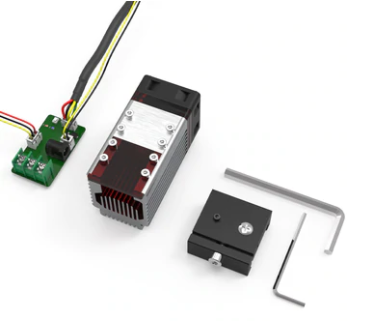
My birthday is coming up soon and I decided to ask for a NEJE A40640 laser module. This cost quite a bit more than the module I have now and honestly I don't need it, it is a total splurge. However the laser has been the most fun I have had with the machine by a longshot. I find it fascinating, and so I want to keep going down that road and see how far you can push a diode laser setup.
![]()
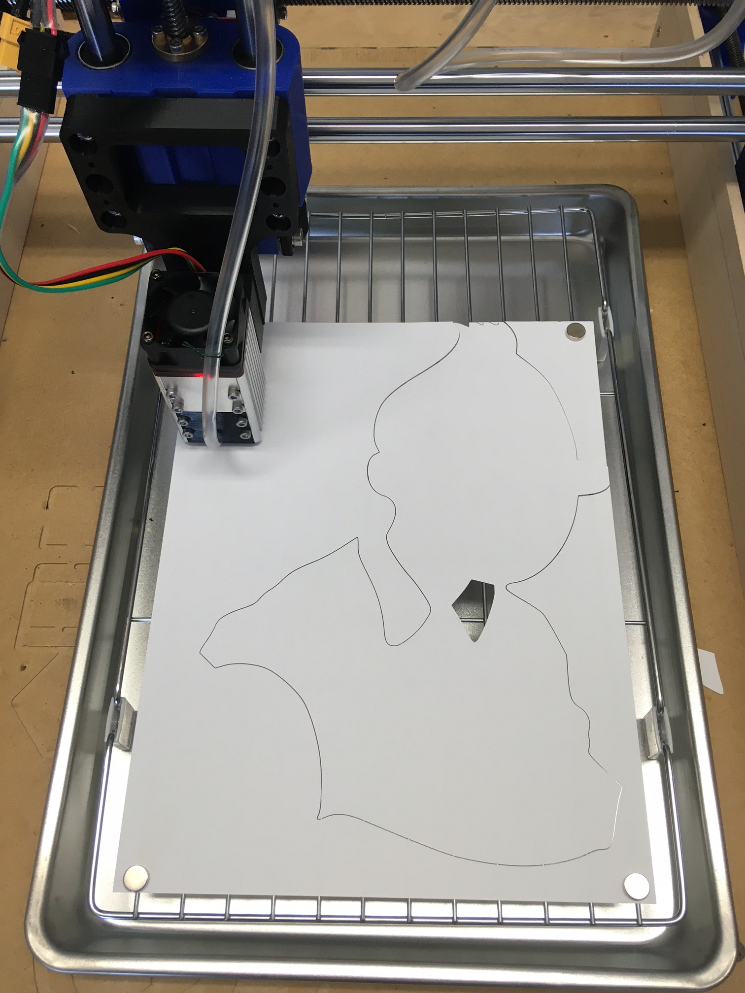
To that end I have been looking really hard at upgrading the laser bed on my machine. I have been using a cheap cookie sheet and cooling rack as a bed but the one I have is small, being a 1/4 size sheet at 9x13 inches. It just barely fits a piece of paper on it, and it has wide parallel bars that I struggle putting magnets on to hold down the paper. On top of that being a cheap rack it is not very level and it has no registration marks or way to reliably line up parts with the laser.
![]()
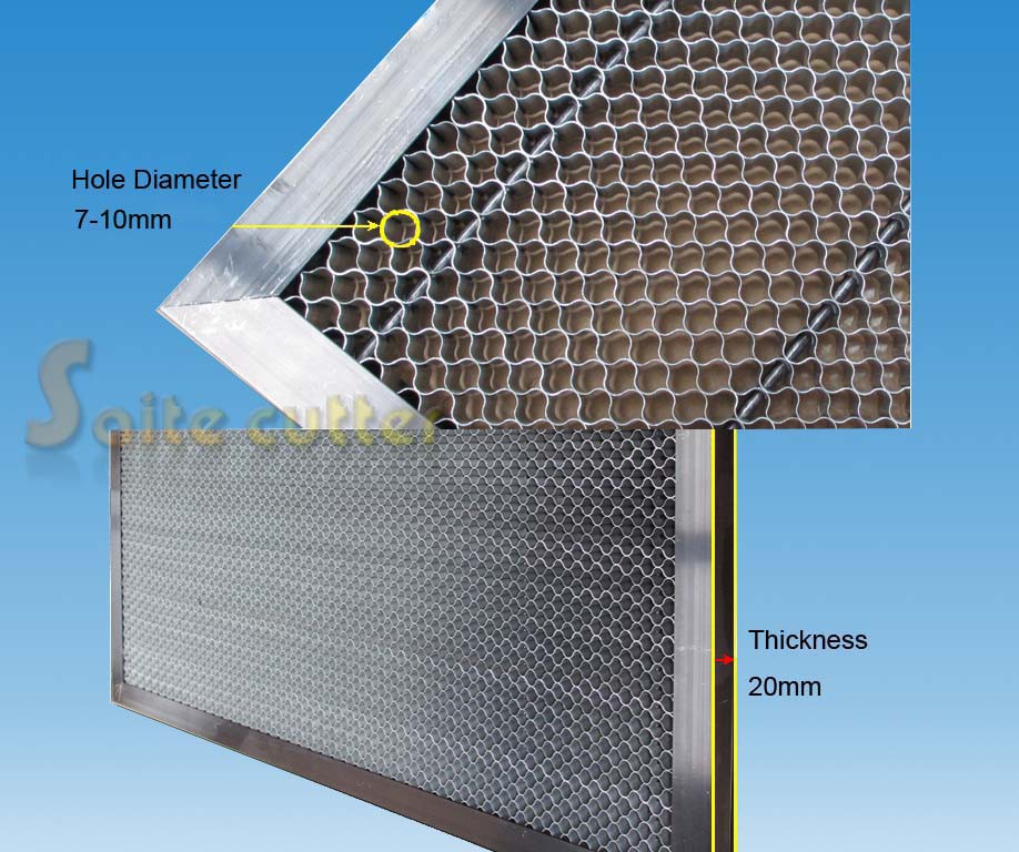
I really want a honeycomb bed. These have an inch of steel honeycomb to support the material, with steel rods running through the honeycomb to support it, and with an aluminum frame around the edge to protect the fragile honeycomb and give it strength. The bed has no bottom, you still need to add a steel or aluminum plate under it to protect the surface of your machine, and you want a gap between the honeycomb and plate so there is plenty of room for air to flow out from under the cut as well. These are expensive to start with and adding that extra material further raises the price. The largest one I could find that would still fit my work volume was a 400x430 mm unit for $70, add in the bed material and it is around $100 plus some effort to put it all together. Plus you loose 50 mm of working volume because of the edges, so you can only use a max material size of 350x380 mm, that is large enough to handle 12" plywood squares, and letter paper, but nothing larger.
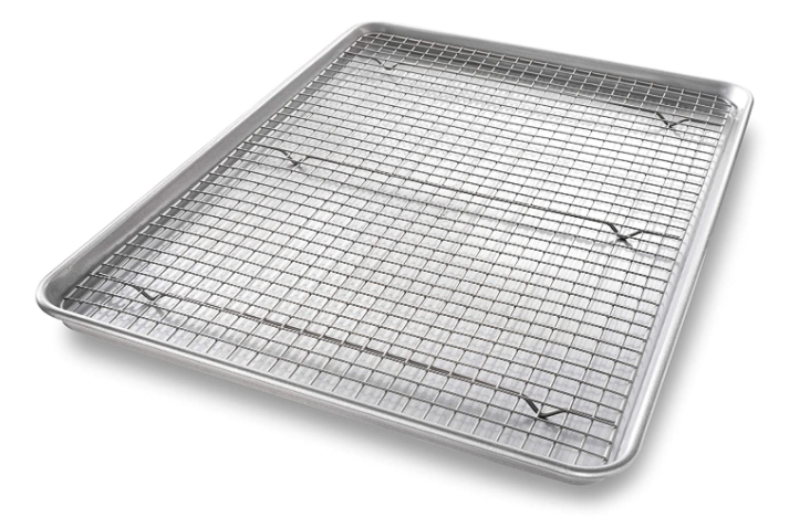
That is way outside of my budget for this machine so I have been looking around all over the place for an alternative that is lower cost but almost as good. I ended up settling on using a larger cookie sheet and cooling rack. I found a 3/4 sheet with rack for $35 that is 21x15 inches (534 x 381 mm). My laser can only move 18.5 x 14 inches (470 x 355 mm) so this is larger than my working volume and yet it still fits on the bed of my machine. It also uses a grid pattern rather than parallel bars, that should make it easier to put weights or magnets on top of the piece without falling between the bars. I could save $10 by going down to a 1/2 sized sheet pan at 18 x 13 inches (458 x 331 mm) for $25 but I would loose working volume on both sides, I think spending the extra $10 is justified.
The whole structure is still just not level and sloppy with no registration or repeatability. I'm planning on mounting it to a piece of MDF that can sit on top of my spoiler board and slot into pre-existing holes on the board so it always ends up in the exact same spot. Then I want to add leveling feet to the cooling rack so it is also hard mounted to the board and easily leveled. Finally I want to add a right angle at the lower left corner that is perfectly registered with the laser head. This can all be done with the help of a few 3D printed brackets and some plywood (in theory).
This is a tough call, on the one hand with a bit of work the honeycomb board would be an excellent bed, but on the other hand it is still too small and would be one of the most expensive parts of the whole machine. I think with a bit of work I can overcome the shortcomings of my baking sheet and make a good bed for 1/3 the price.
Here are all the measurements I used when working this all out.
Baking Sheet Sizes
26 x 18 (661 x 458) - full
22 x 16 (559 x 407) - 2/3
21 x 15 (534 x 381) - 2/3 Nordic Ware
20 x 13.5 (508 x 343) - 2/3 cooling rack
18 x 13 (458 x 331) - 1/2
17 x 12 (427 x 300) - 1/2 cooling rack
13 x 9.5 (331 x 242) - 1/4Material sizes
24 x 12 (610 x 305) - plywood
12 x 12 (305 x 305) - plywood
11 x 8.5 (280 x 216) - letter
14 x 8.5 (356 x 216) - legal
17 x 11 (432 x 280) - ledger or tabloidDimensions
24 x 15.75 (610 x 400) - Max bed size
18.5 x 14 (470 x 355) - Max movement
16.75 x 14 (425 x 355) - Max move on bed -
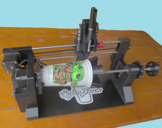
CylinDraw
01/29/2022 at 03:42 • 0 commentsI came across a project that uses an x/z/a rotary setup to draw or engrave on the surface of a cup. It is mostly 3D printed and appears to be very well thought out. They even have there own software that can convert a bitmap to a stippled pattern ready to be drawn. I don't think you could use there software with my rotary axis, but it is nice to see others working on new rotary software.
I also came across this blog post about a drag knife. They are using a tool called dxf2gcode to convert vector drawings directly into gcode that corrects for the drag knife offset. It looks like an interesting tool, and worth a second look. I had trouble previously when I tried loading a large svg file into fusion360, it bogged down and was running painfully slow. It would be good to have a new drag knife tool that can handle large files.
That blog has several interesting posts hiding in it. Search it for laser, cnc, and drag knife and you will find them easily enough.
There are rumors that LightBurn will be adding drag knife support in the near future, and possibly support for pens and engraving bits (drag bits). This would be great, lasers, pen plotters, drag knifes, embossers, and drag bits are all basically the same thing. There are small differences but one program should be able to support all without adding a lot of extra complexity.
*** Edit, I tried dfx2gcode and it seems to be a reasonably well thought out tool. However it is designed for LinuxCNC and not GRBL and is using some more advanced gcode calls that grbl can't work with. I'm sure with enough effort you could write your own post processor to work, but a quick search online and it does not seem like anyone has done this yet. Also this is a post processor tool, there is little logic there to work out part placement or scaling of the design so you need to think that all through when making the dfx files.
-
Crimp my style
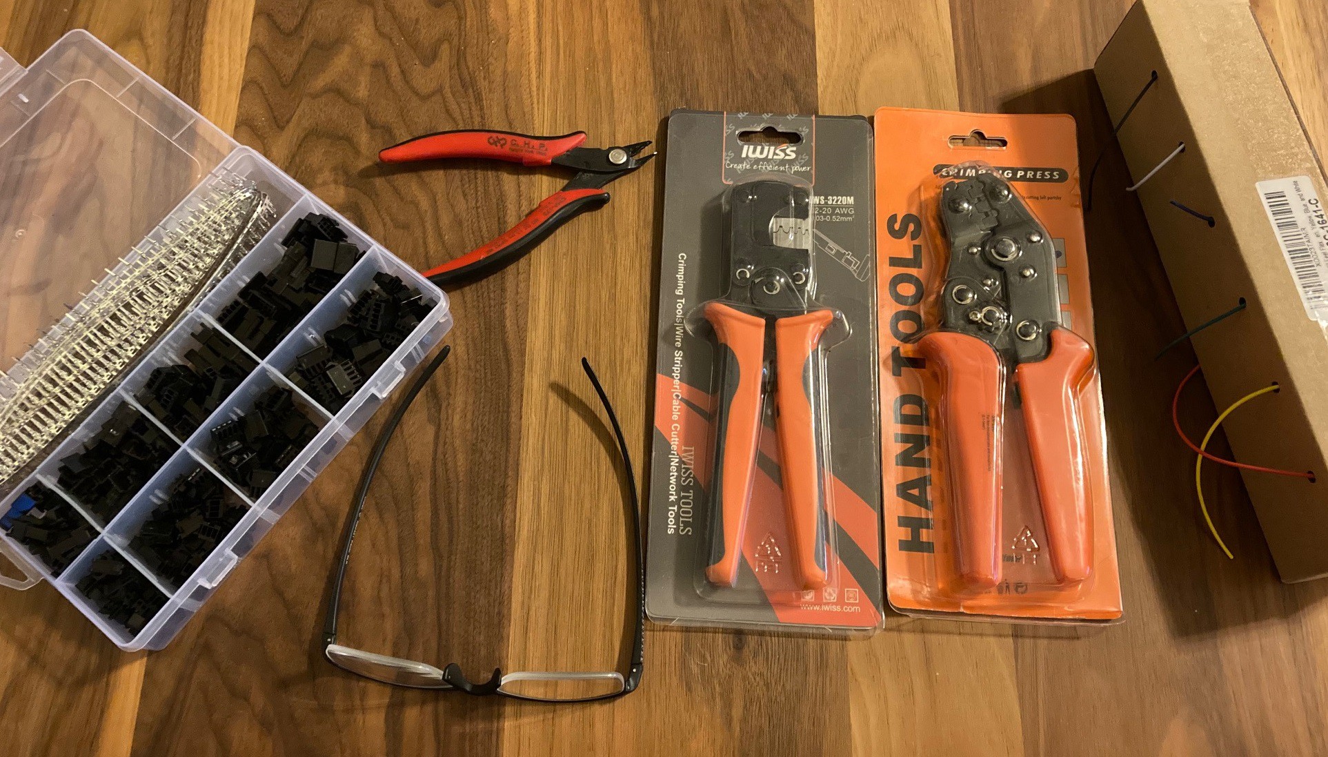
01/27/2022 at 04:58 • 1 commentI have been struggling getting good crimps from my crimp tool so for Christmas I asked for a new crimp tool. My wife still thinks I'm nuts, but she bought it for me anyway.
![]()
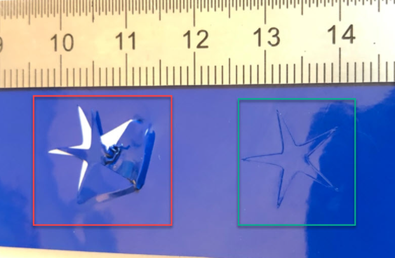
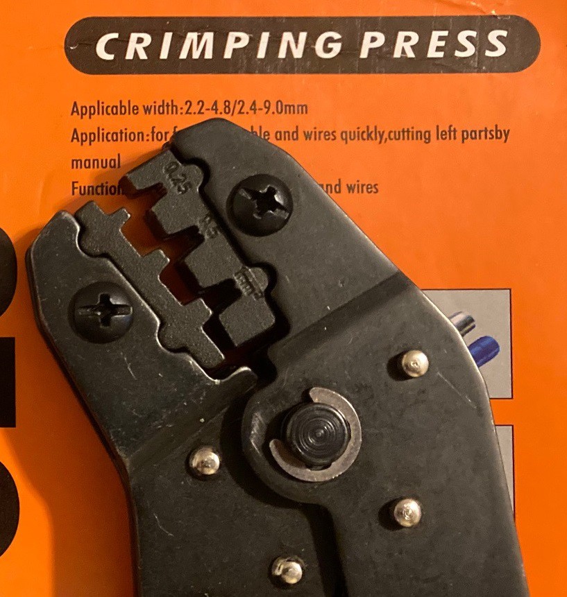
My old tool was a Wovier SN-28B, this is using a cast metal pair of jaws that are not well formed. I have never had much luck with these. The jaw is so wide that I can't see how far to insert the wire when crimping. I have resorted to marking the wire with a marker before inserting everything in the crimp tool just to make sure I can get it all lined up. These are designed for crimps between 2 mm, 2.5 mm and 3 mm wide, however they are marked 0.25, 0.5 and 1mm.
![]()
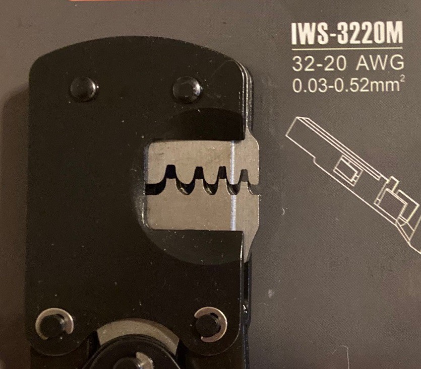
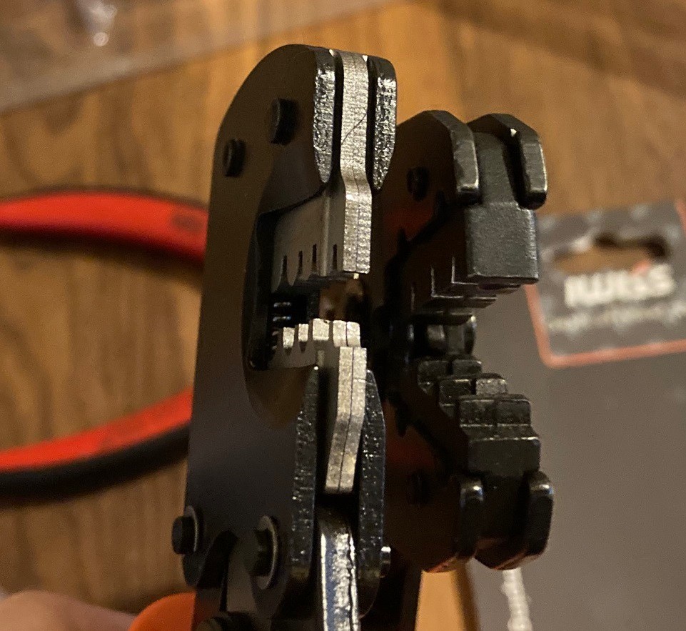
My new tool is a IWISS IWS-3220M crimp. This uses 4 pieces of EDM cut steel to form the jaws. That lets the jaws be formed quite precisely. When fully crimped the jaws touch each other everywhere, there is no room for the metal we are crimping to slip out of the jaws. These are designed for 1.0 mm, 1.3 mm, 1.6 mm and 1.9 mm wide connectors. This does not actually overlap with the other set of crimps, although the 1.9 and 2.0 mm holes are very close.
![]()
You can see the new set on the left, the jaws are just wide enough to crimp a connector, while the ones on the right are 2x wider than they need to be and it is difficult to see what is going on when your using them. This is the main problem with them, although the poor registration of the jaws does cause trouble as well.
![]()
I decided to run a quick test. I have some 22 AWG 6 gauge wire, two crimp tools and a box of crimp connectors. As a small tip, a pair of reading glasses works well as a magnifying glass for looking at small wires. They are annoying because they tend to have a very short focal range, so looking away from the work will give you a headache, but they are not as cumbersome as a desk mounted magnifying glass and they don't need any hands to operate.
![]()
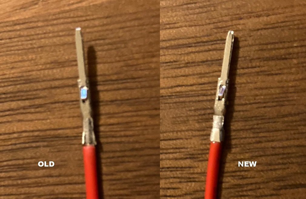
My camera was not happy trying to focus in on the wires so these are a bit fuzzy. But you can see the old crimp on the left and the new on the right, done with the 2mm and 1.9mm holes respectively. The metal of the crimp that goes around the shield has escaped past the jaw and been bent backwards. This leads to the small tabs falling off and makes it harder to insert the crimp into the connector housing. With the new connector the crimp is round with none of this blead and the wires are very strong.
Both crimps are very snug when used with this gauge wire, after crimping the connector gets stuck in the tool and has a small warp to it from being compressed too far. However using the 2.5 mm hole on my old crimp leads to a crimp that is loose and that can be easily removed from the end of the wire.
I'm happy with this new tool. It is better quality than the older one and much easier to use. It would have been really handy a month or two ago when I was trying to rewire my machine, however I have a few poor crimps to redo already so it will get used plenty.
-
Future Plans
01/25/2022 at 05:23 • 0 commentsIt is time again to summarize future tests that I need to run.
- Test new wire crimpers out. I upgraded my cheap $10 crimpers for a cheap $25 set of crimpers, maybe they work better.
- Cut aluminum, in particular cut a corner touch plate out, if I can find a block of aluminum somewhere.
- Cut/engrave plexiglass. I have no ideas here, but I do have a scrap piece.
- Test my speed/feed calculator out and try to work up some reasonable speeds/feeds for various materials.
- Test the output of gcode ripper on my rotary axis.
- Pick up a diamond drag knife tool and try etching glass or metal.
- Look into a honeycomb work table for the laser bed.
- Make a proper drag knife bed.
- Come up with better drag knife software than fusion, or work out how to load large svg files into fusion without it choking.
- Add a removable dust shield across the back of the work area to reduce chips flying all over my shop.
- Look at a stronger box fan to see if we can improve fume extraction. Or investigate a more focused extractor.
- Put Loctite on all screws. I have rattled quite a few loose over the last year and a half. I should have done this initially.
- Reinvestigate laser focus for optimal cut depth, in particular work out of moving the tool over 0.5mm can lead to a deeper cut.
- Build a full size drag knife using a box cutter blade.
- Etch paint off of a tile and/or slate rock
- Try engraving on wood using the laser
- Try doing an inlay on wood using the v-bit.
- Try doing a 3D carve using a ball nose bit.
- Try doing an inlay with epoxy.
- Actually come up with a project to make!
-
More Feed
01/17/2022 at 03:42 • 0 commentsHere is another interesting guide to feeds and speeds. This one seems much clearer than the others I have read.
-
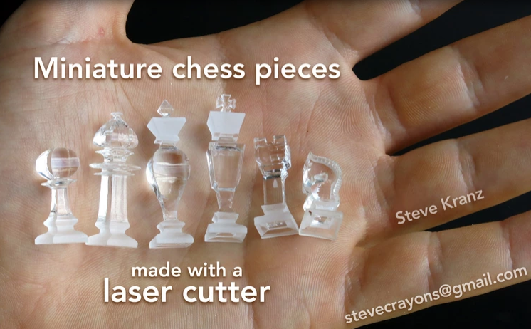
Chess
01/16/2022 at 05:12 • 0 commentsHere is another interesting take on rotary type cutting. In this case they are using a laser to cut a profile out, then turning the part 90 degrees and cutting the same profile out again. This produces a complex 3D profile with a relatively simple 2D drawing. In this case you don't need a rotary to pull this off, but if you took the idea further you could cut on 3 or more orientations and use the rotary to more quickly orient the part.
This is something you could do just as simply with a bandsaw. Honestly it is not a very good match for a spindle, but it does show how thinking a bit outside of the box can give you interesting results.
-
Hope
01/16/2022 at 04:26 • 0 commentsHere is a project I came across that is a new take on the rotary axis. This uses a rack and pinion to rotate a part when the Y axis moves, basically turning y motion into rotary motion. This is similar to the belt driven solution I posted earlier for lasers but this is ridged enough to use a spindle with.
Here is another thread on a similar project. They are programming the mill by drawing up 2D paths, so for example they draw the profile of a bat on the XZ plane and extrude it horizontally, then wrap that to fit the rotary axis. In there case there rotary is driven by the Y axis so instead they need to do a bit of math to scale things correctly and just machine it as if it was a regular XYZ machine.
![]()
![]()
Anyway the point here is that I'm overthinking things a bit. Yes it would be nice to model a 3D part and have it cut out perfectly on the rotary axis without modification. But it is possible to get some complex shapes out of the rotary using 2D cad (2.5D) and some creativity with the math.
-
Frustration!
01/16/2022 at 00:14 • 0 commentsI have been hung up on what software to use for my rotary axis for weeks now. It is getting very frustrating. I have tried every software on my list twice now and none of them are winners so far. I feel like somewhere out there is a great piece of software and I just can't find it. Here is a breakdown of what I have found so far.
- GrblGru - This has soo much promise but somehow it falls short. It is clear from videos online that older versions of this software can get the job done but I can't get the latest version of the software to work. I get something close to a rotary carving but it comes out all distorted. I have tried to dig up older versions of this software but with no luck so far.
- SketchUCam - This is well out of date and only works with old versions of sketchup. I only gave this a half hearted attempt, but I could not work anything out at all with it. It is a poor long term solution being that it has not had serious work done on it for years and it is unlikely to move forward ever.
- FreeCAD+path - This is probably the most frustrating of the bunch. All the pieces are there and yet it does not work at all. As a cad program it is annoying, everything that Fusion360 does so simply is tedious in FreeCAD. Trying to use path for 2D cutting is frustrating, but functional. However I was unable to make the rotary support work at all. I need to revisit this again but I have a feeling the solution is to install some unsupported patches to get it working. It should be a good solution in 2-3 years when they finally get path all sorted out.
- Grbl-Plotter - I actually like this one a lot, however it is laser only. If you don't already have LightBurn then this is a good alternative.
- G-Code Ripper - I have had the most luck with this one. It appears to properly wrap a 2D carve around a cylinder. However when I tried to load the resulting gcode into UGS it does not look like it is correctly driving the A axis but rather messing with the Y axis. I need to sit down at the machine and see if UGS is just rendering the moves wrong or if G-Code Ripper is not generating the right code.
- CNC Wrapper - There is no way to get your hands on this, and looking at the wayback machine it seems to have been out of circulation for several years now. I found an old version from a dodgy website and tried to run it but it is not functional. This is a more polished version of G-Code Ripper in theory.
- D2nc - I could not work out how to use this to wrap gcode, maybe I'm just not smart enough. It looks like a nice enough tool for tweaking gcode, although it is a bit pricy for what it appears to do.
- CamBam - I spent some time looking into this and find it to be a frustrating tool. I have looked into it previously when I was investigating cad packages. It does not actually have rotary support built into it. There are some very old plugins out there that can unwrap 3D models and wrap 2D gcode onto a cylinder, much like G-Code Ripper. There is some potential for this to work, but I spent several hours on it and did not make much progress. Still it is worth another look.
- DeskProto - This one works great, it is amazing how easily it is to work with. It is just what I'm looking for. However the demo version is completely crippled and can not generate functional gcode so I can't test the results. And it cost almost as much as my whole machine for a tool that is not as nice as Fusion360 (but still nice) so it is hard to justify the cost just for the occasional rotary work. If I do pony up money it will probably be on this. If it was $80 I would have picked it up already but for almost $300 I could get myself a better laser or a table saw.
- vCarve Desktop - This appears to have rotary support but when I grabbed the free version I could not get it to work. I followed there guides but the rotary modules are not installed or activated. I even went all in and downloaded Aspire but it also was missing the rotary modules. This could be user error but I went over there documentation several times and did not see a way around it. I suspect the rotary support is just not enabled on the demo. vCarve is like CamBam, I find it very counter intuitive to work with, I much preferer Fusion360. However plenty of people manage to make it work so it is probably just that I'm not comfortable with it yet. Again the cost is very high for the desktop version, for the full Aspire it is crazy expensive.
- Fusion360 - This looks great, but the rotary support is disabled. I know in my heart that this can do everything I want however the cost is just way too far out there. $500 a year for rotary support is probably nothing for a commercial shop, but for hobby work that is close to my annual budget for all my projects. My wife is a teacher and I have a kid in highschool and college. I may abuse one of there emails to get a student license. However that is only a temporary solution, eventually they will graduate and I will need to pay for it or loose rotary support. Besides this offends my sense of justice, somewhere out there is a good piece of software that supports a rotary attachment that is priced for the hobby market.
I'm not sure how many of my issues are user error or how many of them are just poor pickings. I'm a computer developer by trade so I consider myself a reasonably qualified computer user, but still I'm having no luck at all with any of these packages.
---
Edit: I found another wrapper tool called GCODE Wrapper that is very similar to G-Code Ripper but it only wraps gcode without the other features. The output from it looks just like the output from G-Code Ripper so I suspect that UGS is at fault for the code looking wrong.
It gives me some hope that one or the other can be made to work. Both are compromises, you cant directly model a part and turn it into gcode, you have to find a way to unwrap the 3D model first. It is better than nothing but it is not full 4th axis support.
-
Small progress
01/08/2022 at 05:13 • 0 commentsI spent some time today trying to get the rotary axis programmed up using GrblGru. I'm convinced it can work, but I have yet to make it happen. This is a frustrating program, it has a lot of potential but it is buggy, slow, and confusing. Still I will keep at it, for sure all the pieces are there and it can turn my rotary, I just can't work out how to make a 3D carve.
I have started looking in earnest for alternative programs that could work. For less than $400 I can find several, but trying to get something for free or a reasonably small fee is proving tricky. That is trying to spend as little on the software as I did on the hardware is tough. It is a real shame that Fusion360 has disabled support for there rotary axis in the non commercial license. They could have had a big impact on the small rotary machine market. LightBurns rotary support has had a measurable impact on the laser rotary community, it is a much more mature community with many options for hardware and software.
I have put together a google doc with my findings so far. If you know of any tools I have missed, feel free to drop me a note.
https://docs.google.com/spreadsheets/d/1N2nNWQVzIz3wmb2btbQ4Dors2ToLn0SSubN6PVv-1Zo/edit?usp=sharing
Edit, it looks like FreeCAD has been working on rotary support and the latest release has made some progress. I'm going to take a hard look at this, if true then not only is this a good way to handle rotary support, it is a reasonable alternative to Fusion360 that is truly free and open source.
MultiBot CNC v2
A low cost 3D printed CNC that can be built with minimal tools yet is capable of great things.