-
MCPCB - METAL CORE PCB
12/24/2020 at 07:09 • 0 commentsSince there is no looking back now, there is only moving forward, MCPCB seems like the only logical choice. Will try to find a way to design the files in Kicad.
From what i gather here and there, no vias (or very few) is allowed.
It´s possible to make it with 2 copper layers. Either with aluminium sandwiched in the middle or as a backing plate.
Im thinking to maintain the fan´s.
Now, having come to the conclusion, that the heat-dispersion (cooling) and thereby the mechanical buildup of the finished design, is fundamentally important for a good and lasting design, the inevitable question arises. There are techniques of which the pcb maker connects the aluminium or copper layer of the metal-core pcb directly to the heat-pad of the high-power LED. This technology has different brand names and probably different ways of achieving the same goal. Now back to the question. There is no question about the advantages of such a direct path for heat to flow. The question is how and how much. If a special tool for the process is needed, cost goes up. Especially for prototypes.
So what´s the plan?
My plan is to do prototypes the regular way of doing Metal-core pcb with a layer between the copper and aluminium. The copper thickness will still be 105µm. This way I will validate the design and at the same time learn from the manufactures doing direct heat-transfer MCPCB pads.
-
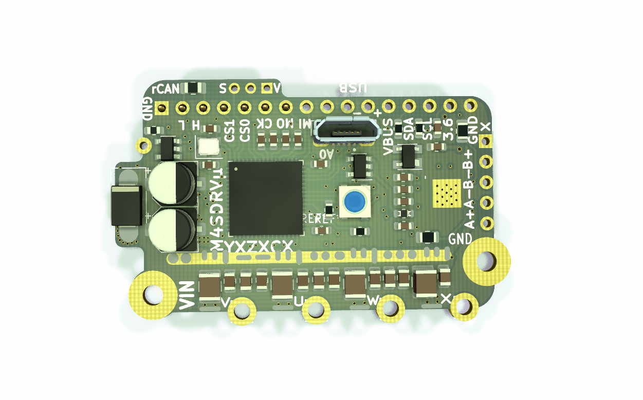
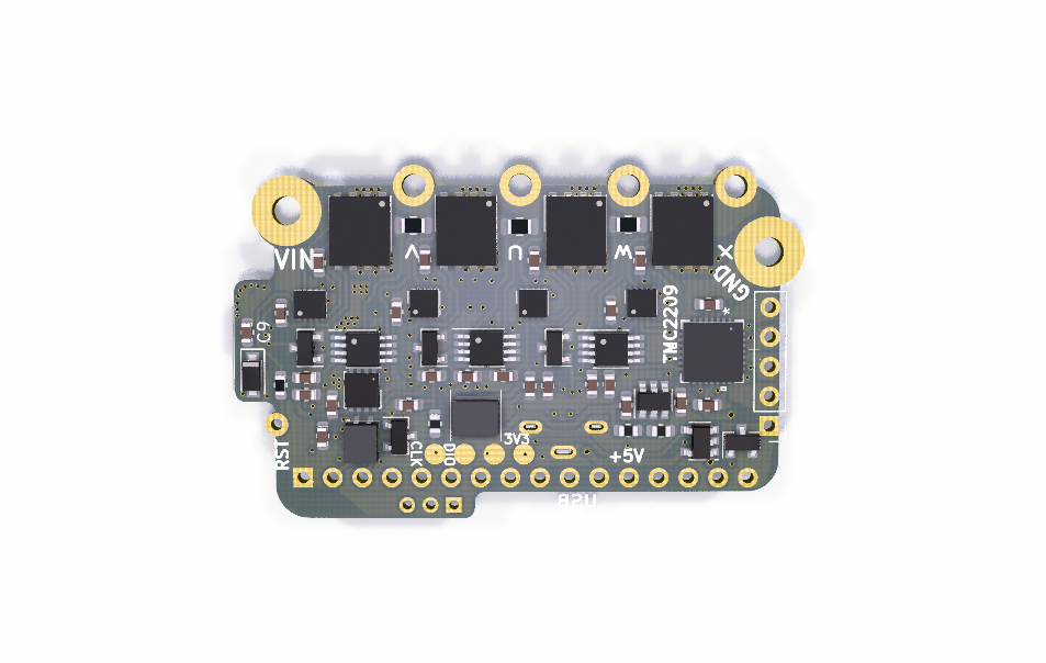
Controller design done
12/21/2020 at 23:38 • 0 commentsAdded 6amp MOSFET next to the TMC2209 stepper pins (A+/-B+/-), tied to ground. X
Added text rCAN next to CAN termination resistor. Note: The two end-nodes in a CAN network must be terminated with 120ohm resistor.
Added AP2161W (active low) to cut USB power when VIN is applied.
Ready for prototypes!
-
Calculating power consumption
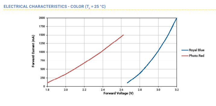
12/15/2020 at 23:59 • 0 commentsWith the below chart, you can se the voltage drop related to current consumption. If we stay well within the 12v, we can drive the leds to their max. The max current is controlled by dimming the LED´s while monitoring current consumption, temperature and PWM.
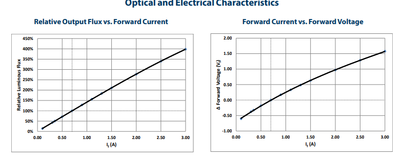
For a string of Photo Red´s from Cree Inc. 4 leds will produce a voltage drop of 10.4 v. (If there where 5 leds on the string, we would exceed the 12v by 1v. Using 5 Led´s on a string would max them out at 1000mA. 1amp times 2,4v is 2,4watt. Driving them to 1500mA gives (2.6v x 1.5A) 3,6watt. 3.6 x 4 LED´s = 14,4watt - 2.4 x 5 LED´s = 12watt. With the Blues there is a even greater gab, since they can be driven to 2amp. The luminus RED´s on the other hand can be driven to 2amp and has a max power dissipation a 5W. (depending on cooling). With a forward voltage at 700mA of 2.35(datasheet) the voltage drop at 2amp is 3.35, looking a below image (source). 3.35 x 5 = 16,75, so well above 12v limit. But then again, this is full on 2amp per LED, which will generate heat. Since this concept tries to explore on how to use this excess heat, the heat is somewhat welcome, but generating that heat, we might as well make the most of it. At 1.5amp the drop is around 3v, so on a 12v string with 4 LED´s, it will not go higher. Something to take into account when choosing LED´s.
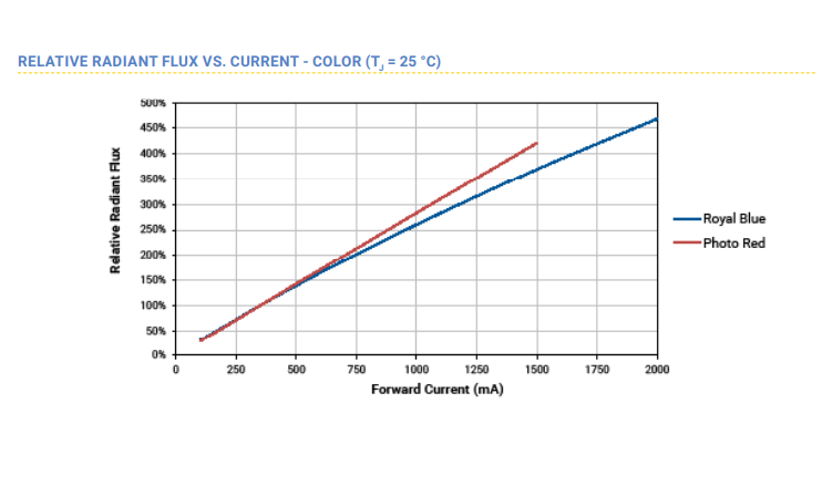
Here is where it gets interesting. Below we have the radiant flux output of the Cree´s. This looks nice and well distributed over the 2amp area which is max for the Blue. So at 700mA the Luminus chart is 100% and the Cree´s is 100% at 350mA. That a pain in the blibinglyblib. How should we compare. The graph looks pretty linear in both cases....... hmm.
Cree red (XPGDPR-L1-0000-00G01) has a min 525 flux(mW) at 350mA. So at 700mA, looking at below graph, it should be 200% = 1050mW flux.
Luminus red (SST-20-DR) has depending on which flux bin up to 990mW @ 700mA. In the low end of their bin it is at 790mW, which is strange becouse that is also seen in the mouser part. Maybe that is why the SST-20 has a lower price tag. I guess the V in the product name implies the bin (SST-20-DR-B120-V660). If we say the V type is on avage 810mW at 700mA. That is quite the difference. 1050 for the cree top line and 810 for the Luminus low end @700mA. This difference is what the price reflects.
There is the calculated output difference in "brightness". But note it is relative.
Anyways, to sum it up. 14,4 watt @1500mA using 4 LED´s on a string. times 8 strings on each controller channel = 14,4*8 = 115.2 watt. 115.2 watt is around 10 amp @12v
-
Cree XP-G3 vs. Luminus SST-20
12/15/2020 at 19:26 • 0 commentsThe Cree XP-G3 and Luminus SST-20 are close contenders. Naturally the prize of the parts and thereby the final BOM is importand, but likewise the efficacy and real world foton flux.
The final current consumption is a big consideration, since the switches and the controller has a upper limet. With that said, it is unrealistic to drive the LED´s a full capacity since this will lower the lifetime of the LED´s.
The temperature rise is difficult to compare, but the Luminus SST-20-DR seem to have a lower Thermal resistance.
My overall verdict, looking at the datasheet and prices, is in favor of Luminus for RED.
Why? The Cree XP-G3 RED does have a higher efficacy but also a higher thermal resistance. And it is twice the prize:
(Source: Cree XP-G3 - Luminus SST-20-DR-B120-V660). A side by side comparison would be interesting, unfortunately the footprints of the two does not mach. The Blue SST-20 does come in two versions, one of witch has the same footprint as the Cree. Seems strange, but maybe a way for Luminus to bind their costomers to this particular part.
Note: The datasheets of the two candidates is hard to compare, since the two manufakturens might have used different methods of measuring umol/watt output. To compare the efficiency, one needs to measure umol/watt with exact same current and distance (conditions). There are some noticeably different specs.:
Here Cree gives a maximum mmol/J, which is staggering 12.0 mmol/J. But is this at 1500mA? To compare, the Luminus state a 700mA value of 4.82 mmol/J. The maximum drive current is 2Amp. So maybe this is the mayor difference. To make the choice even more confusing, the Blue Luminus SST-20-B-A120 has a thermal resistance of a whopping 3.5 C/W. Where the Cree royal blue has a thermal resistance of 2 C/W. Here the two candidates does not differ so much in price. And my preferred choice would be Cree. Since the two has the same footprint, one can mix and mach.
Any real world experience with comparing the two is most welcome.
Cree XP-G3
PPF Efficiency (PPE) at 350mA: Royal Blue(2.83 mmol/J) Photo Red (4.08 mmol/J)
Thermal resistance: Blue(2 C/W) Red (2.5 C/W)
Luminus SST-20
PPF Efficiency (PPE) at 350mA: 3.28 mmol/J
Photosynthetic Photon Flux (PPF) at 700mA: 2.99 mmol/J
Thermal Resistance (Electrical) Deep Red (RTH 1.8 °C/W) Blue (3.5 °C/W)
Note 2: Sustained operation at maximum current will result in shortened lifetime
-
Added 5 x 4pin pwm fan driver (I2C) EMC2305
12/14/2020 at 05:59 • 0 commentsAdded EMC2305 4pin PWM fan driver. The driver monitors the 4pin fans sense output, it ramps up and down based on internal algorithm. The IC next to is is a temperature sensor MAX31725MTA+T with a 150C rating and decent precision. So there is now 5 individually controllable fan PWM outputs with RPM feedback, controlled through I2C. The MAX-31725 temperature sensor has a fast response time, which will hopefully make it a good choice for intuitive LED control based on temperature and current consumption.
-
Utilizing space
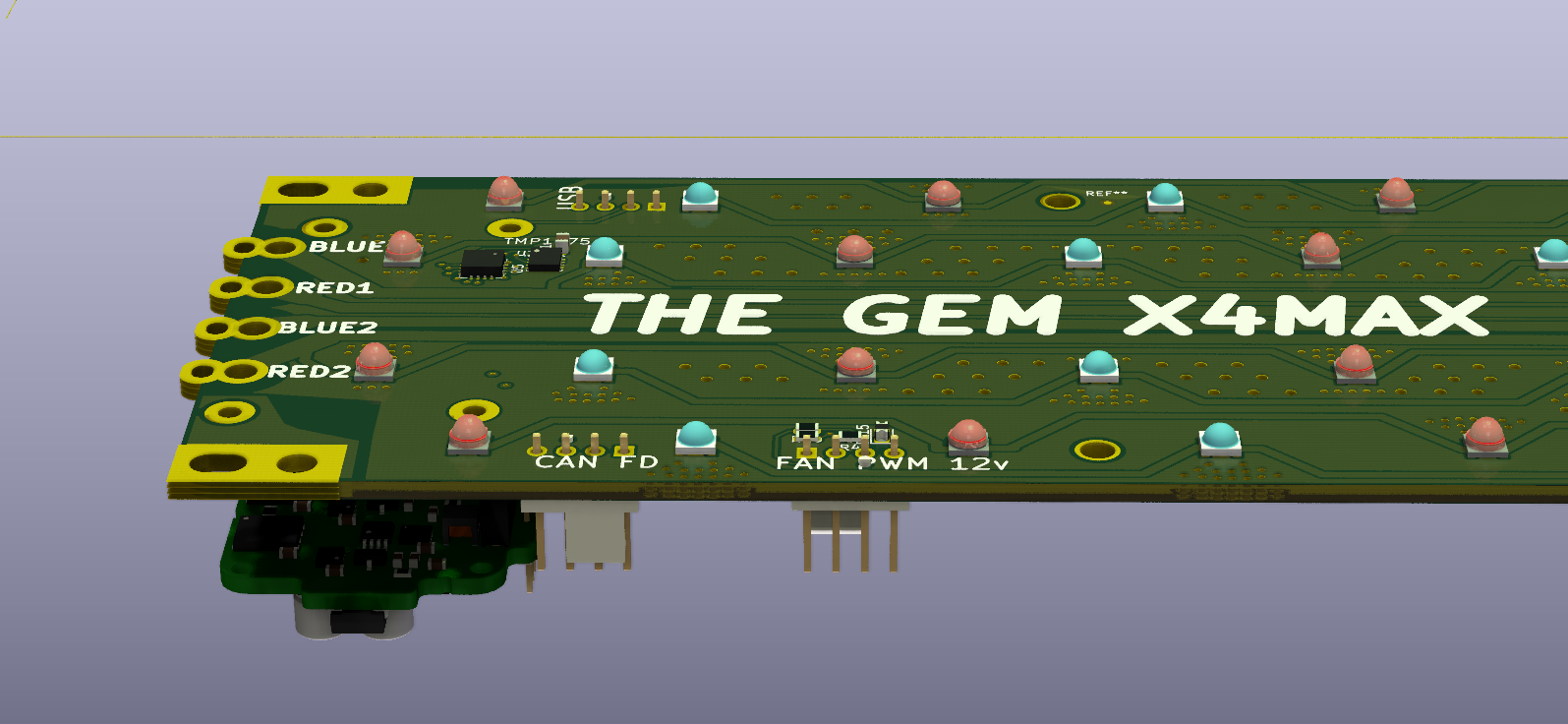
12/11/2020 at 04:51 • 0 commentsDoubled the LED count.
-
CONTROLLER
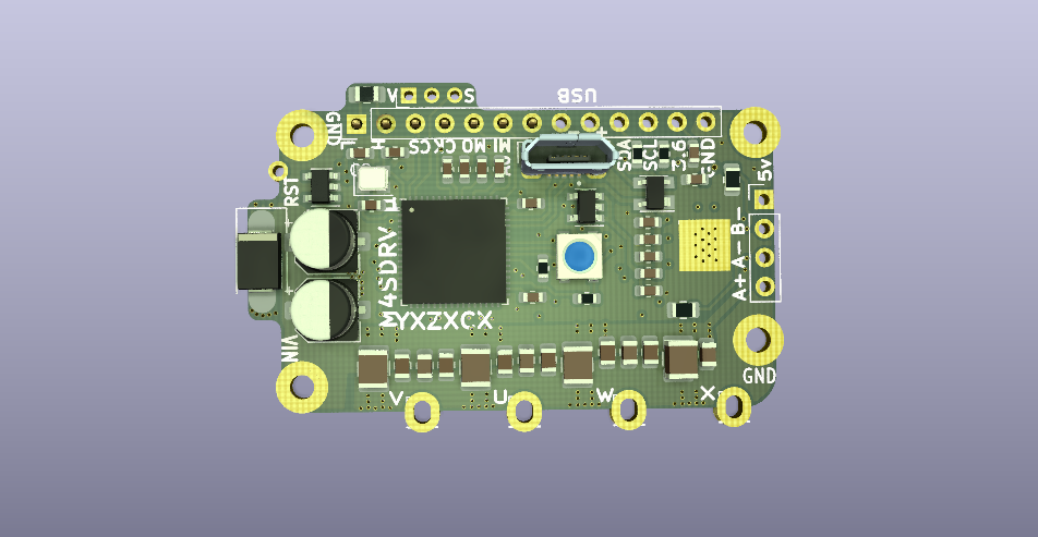
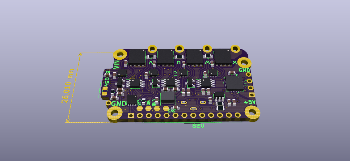
12/07/2020 at 21:44 • 1 commentFeatures:
SAME51 MCU 120 mhz M4 architecture with CAN FD (https://www.microchip.com/wwwproducts/en/ATSAME51J20A)
TMC2209 stepper driver (https://www.trinamic.com/products/integrated-circuits/details/tmc2209-la/)
MOSFETS BSC0925ND Dual channal 40amp 17nC gate charge (https://www.infineon.com/cms/en/product/power/mosfet/12v-300v-n-channel-power-mosfet/bsc0925nd/)
Gate drivers MIC4605-2 PWM indput (https://www.microchip.com/wwwproducts/en/MIC4605)
Current sensors MAX40056 (https://datasheets.maximintegrated.com/en/ds/MAX40056F-MAX40056U.pdf)
Step-Down converter 4v/36v to 10v rail 1amp (https://www.ti.com/product/LMR50410)
3.6v LDO 500mA (https://ww1.microchip.com/downloads/en/DeviceDoc/MIC5219-500mA-Peak-Output-LDO-Regulator-DS20006021A.pdf)
3 x ANALOG HALL sensors (https://www.ti.com/product/DRV5053?qgpn=drv5053)
Analog hall sensors will potentially give a precision of the ADC resolution over one polepair. Thats 12bit (4096:1) (3mm/4096=0,0007mm)
CAN FD physical layer IC MCP2562FD-E_SN 8Mbps (https://www.microchip.com/wwwproducts/en/MCP2562FD)
4 layer PCB w. 105µm outer copper. (Min 0.25 mm. trace width and clearence)
Communication ports:
SERCOM port can be configuered to I2C, SPI and serial.
CAN FD is integrated into the SAME51 MCU.
USB 2.0 full speed. (USB port data-pins is broken out)
-
Exploring enclosure
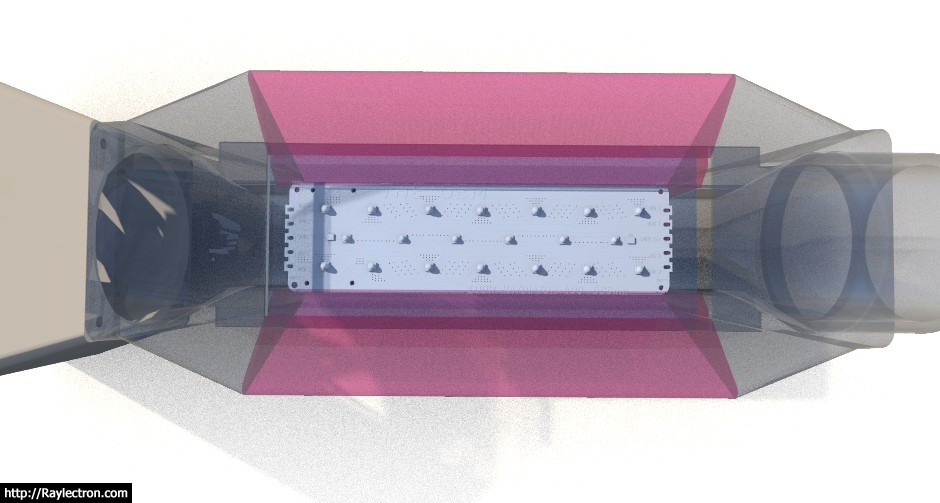
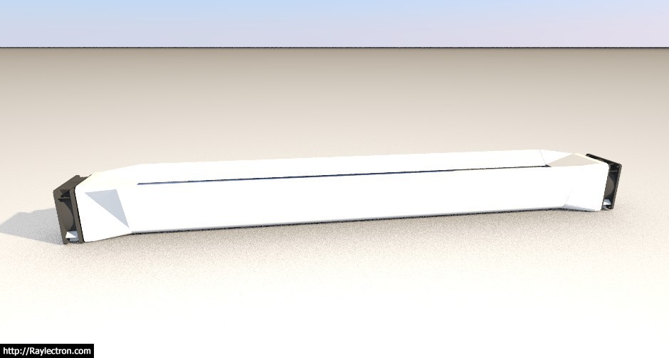
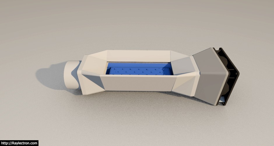
12/07/2020 at 19:12 • 0 commentsFirst draft of a enclosure, will explore this further. I think something made of wood will be nice.
![]()
![]()
![]()
![]()
![]()
 Juan-Antonio Søren E.P.