 Eben
EbenField Test:
They are multiplying:
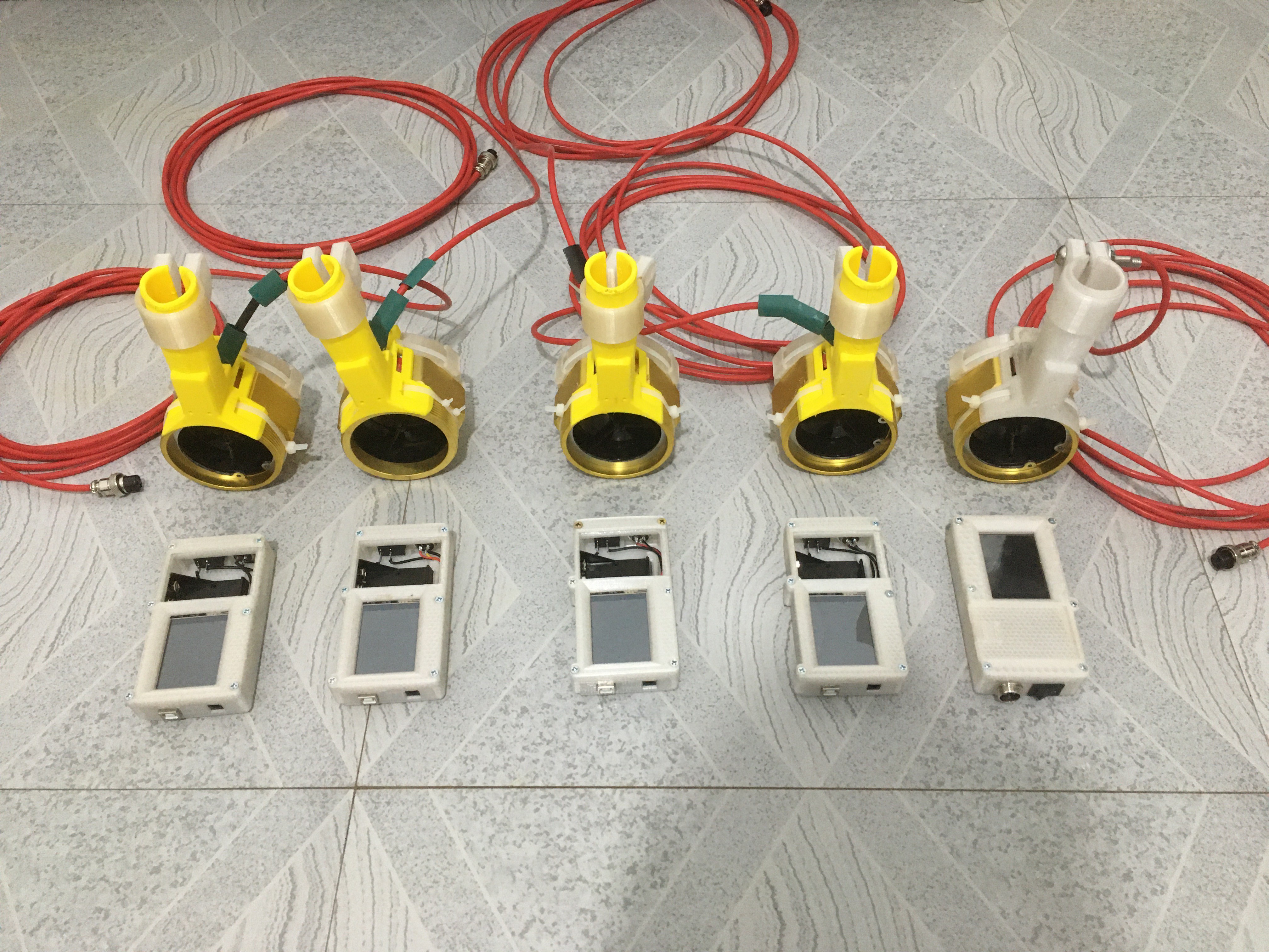
The build 20th of January 2021:
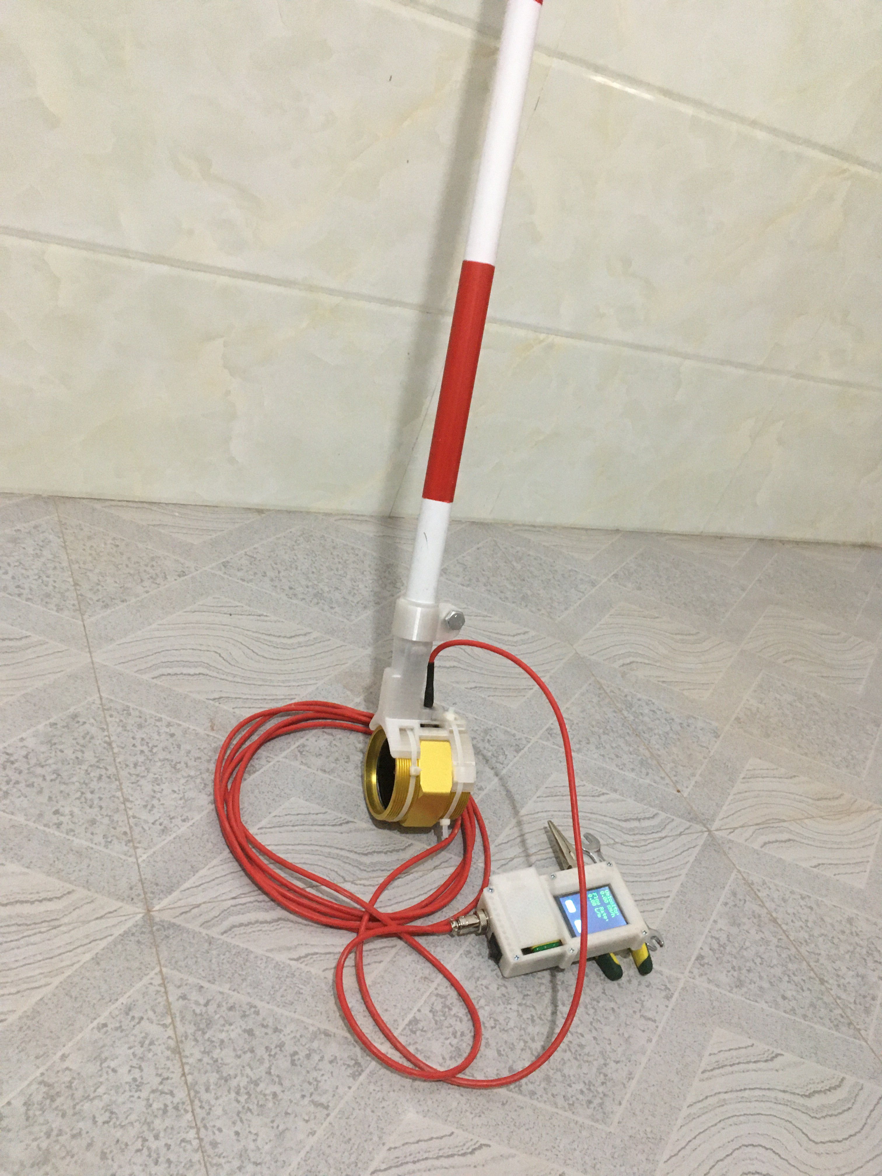
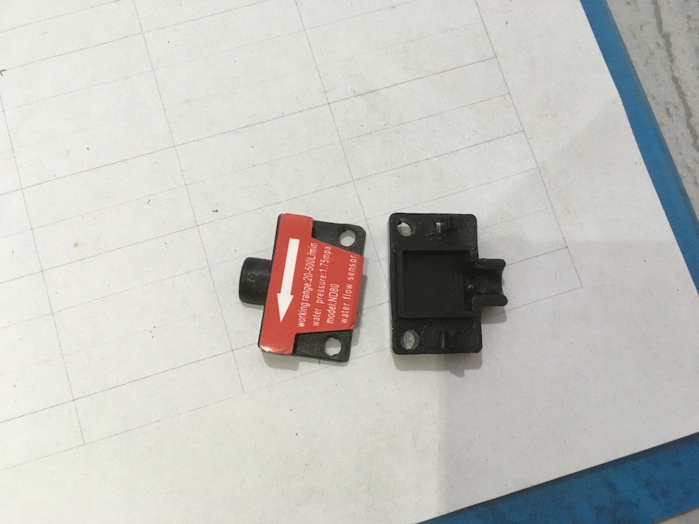
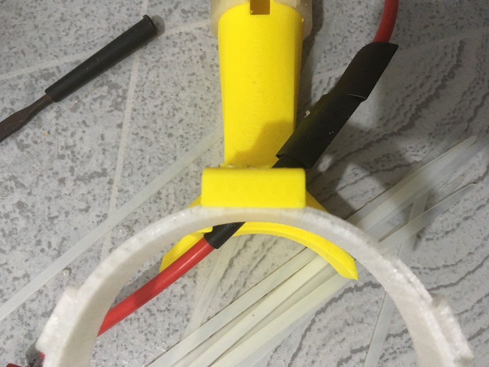
Improvements since the DN50 build: Internal battery housing, on/off switch, aviation connector, DN80 sensor, detachable sensor pole.
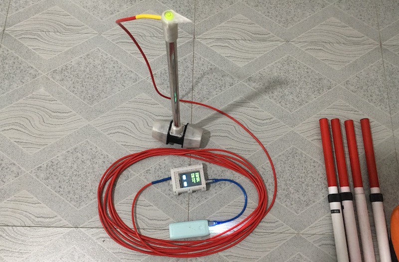
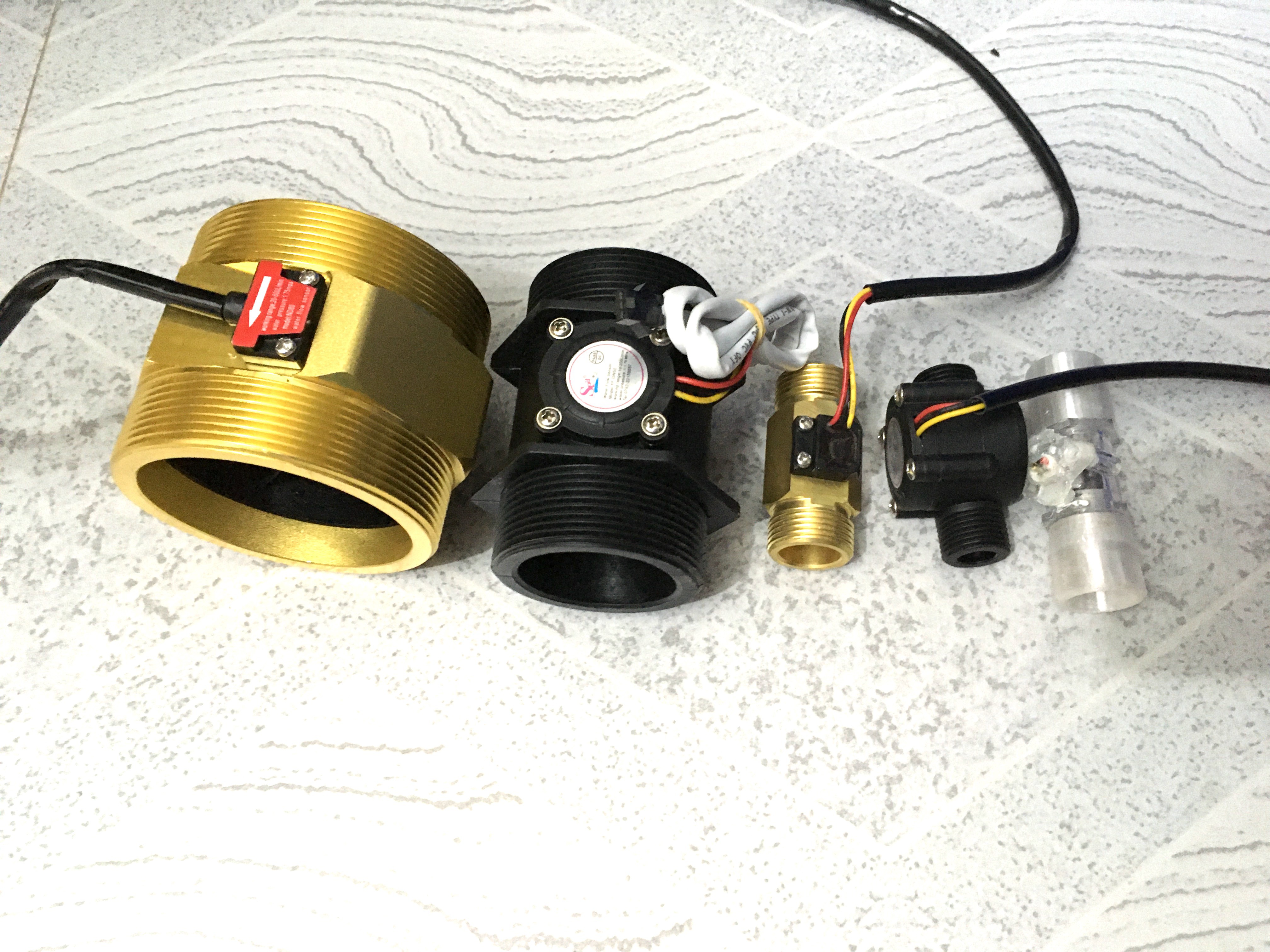
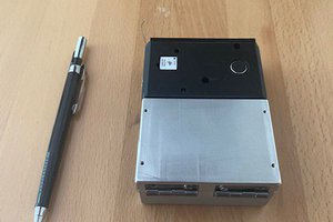
Here is one of the earlier designs using an DN50 sensor.
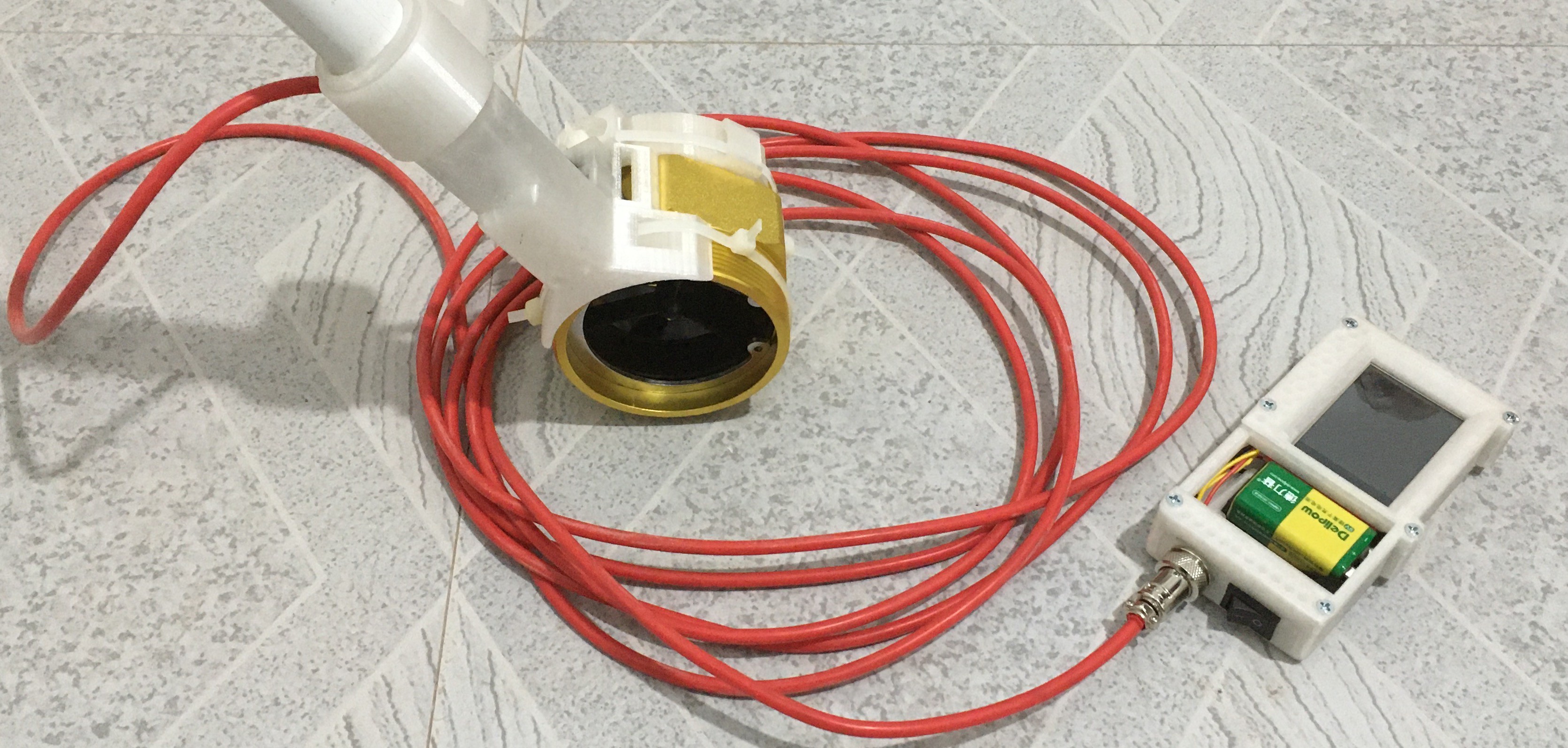
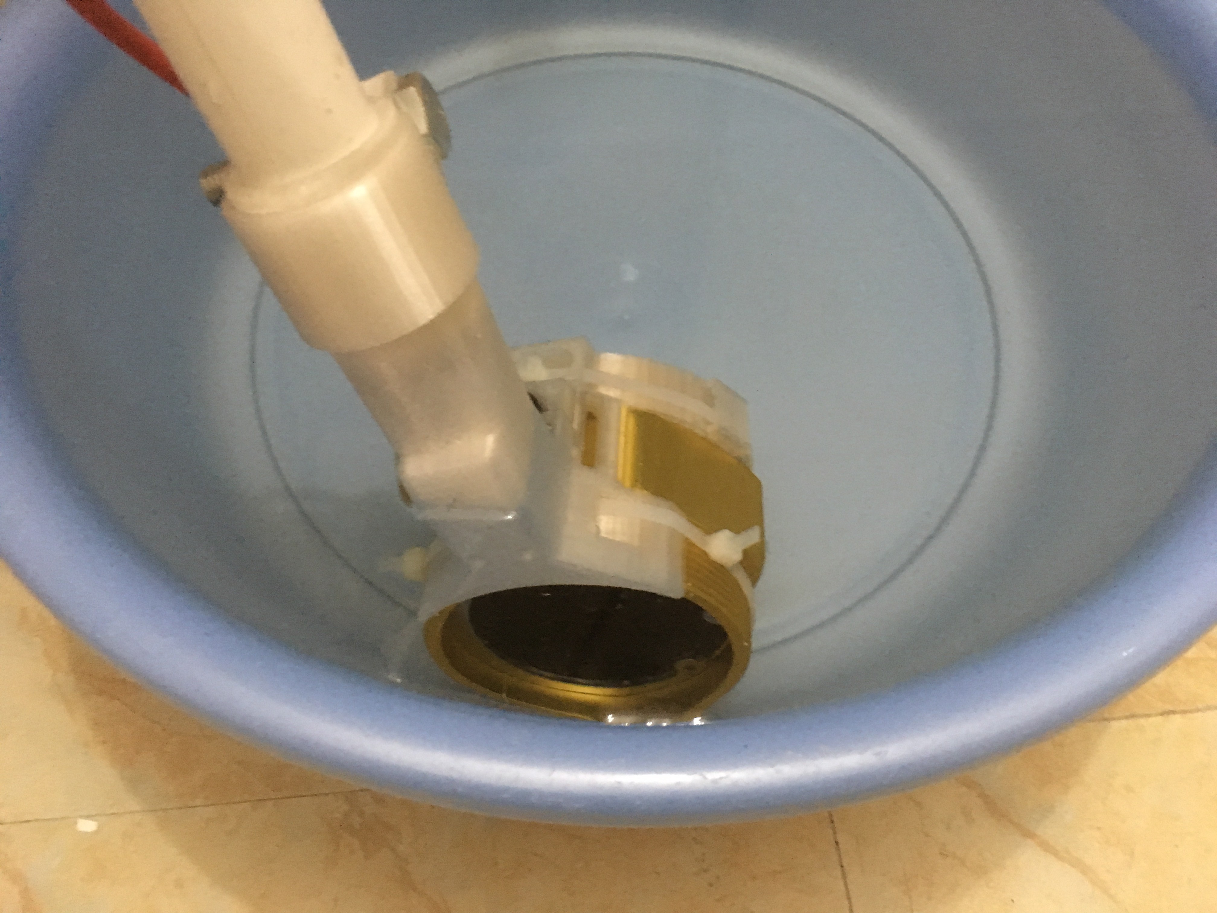
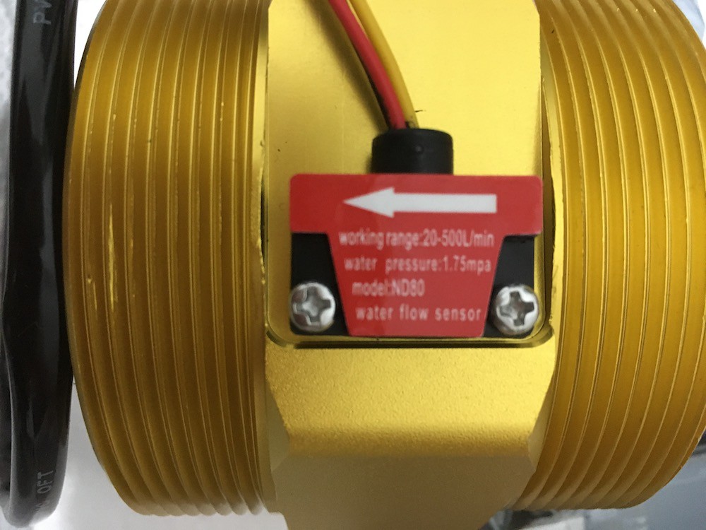
I have switched to using a DN80 sensor, I have created a new Arduino housing that now has an on/off switch, an aviation connector for the main cable and internal battery housing. I'm working to change the firmware to read MPS instead of Km/H.
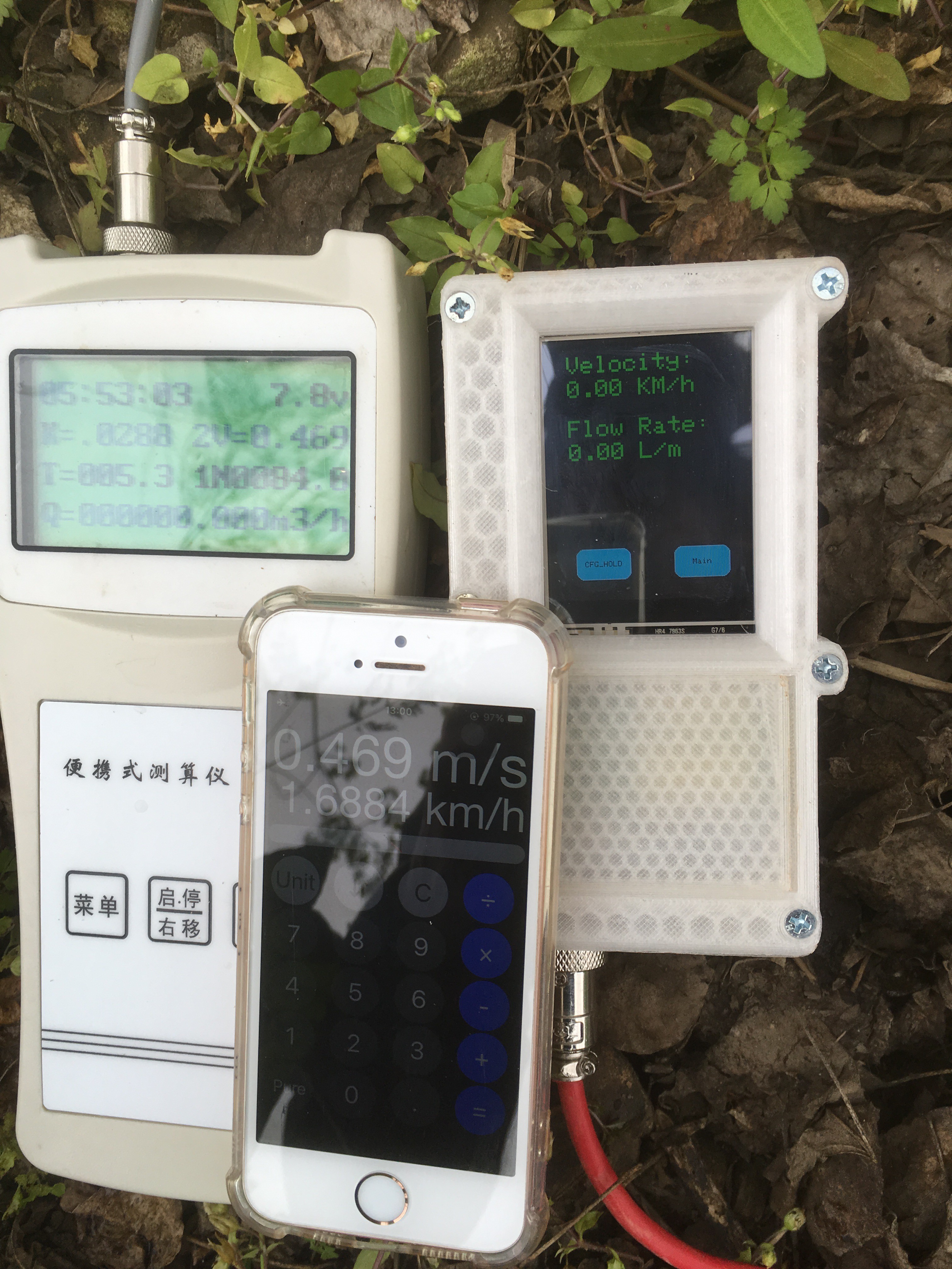
After that I will do some tweaking comparing the readings with a purpose build flow meter to increase the accuracy. If all of these steps go as planned then I will complete the build instructions and finish this project.


 joedefa
 Tom Meehan
Thanks a lot for sharing this nice project! We constructed one and tested it the last days on a field trip with students. We also compared it with a highly sensitive commercially available flowmeter and it worked very well! We maybe will do some adjustments in terms of height adjustability of the sensor. NICE WORK !!!