 Eben
Eben-
1Print all the 3D printed parts
Download the parts from here: https://www.thingiverse.com/thing:470091
After printing, clean up the prints and make sure everything fits together.
-
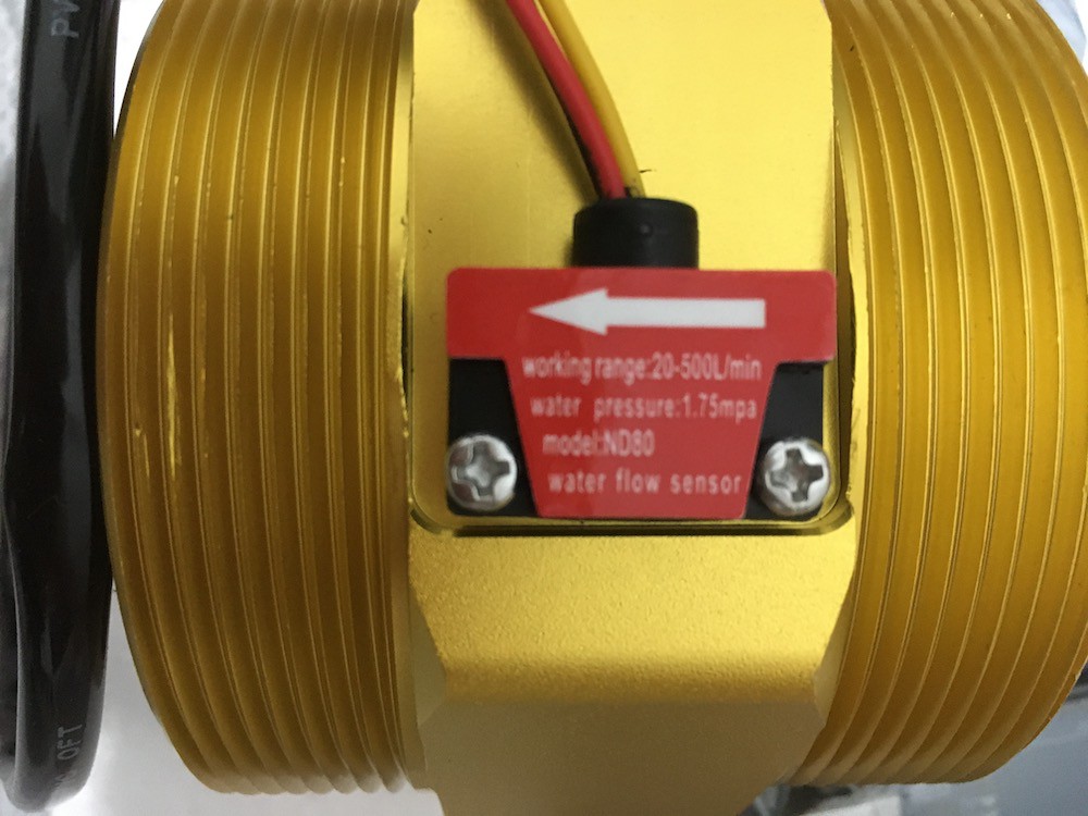
2Asemble the sensor end with the DN80
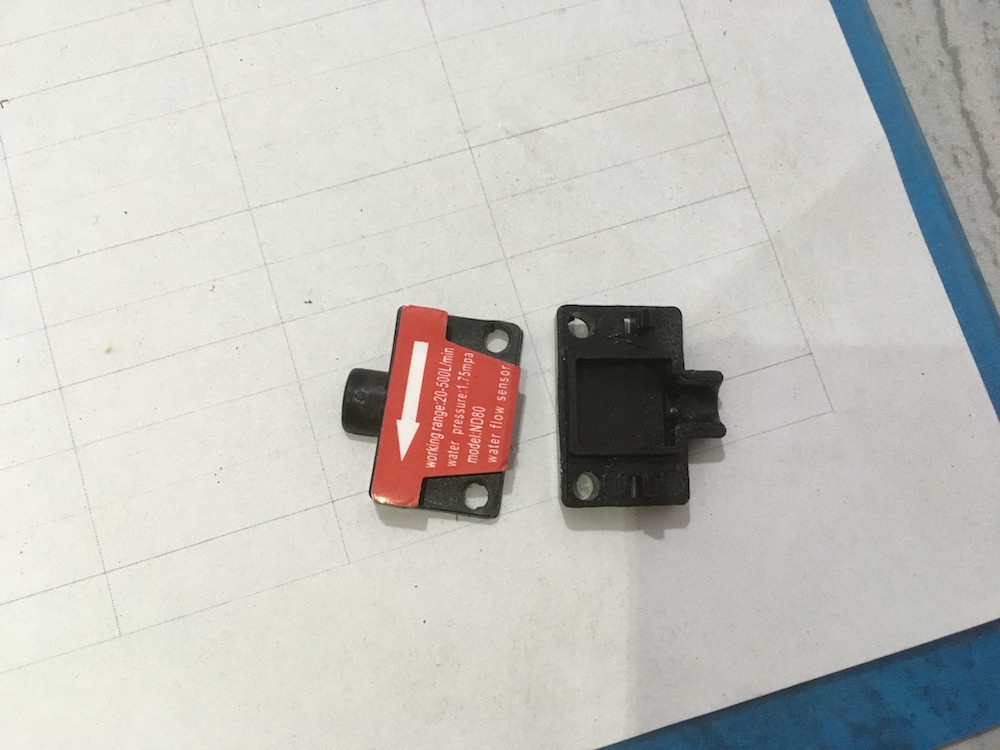
Unscrew the black box from the top of the sensor by removing the two fillips head screws.
![]()
Use a knife blade to carefully pry open the small black box with the 3 wires coming out of it. There maybe some black silicon round the edge where the wires enter the box.![]()
Get the long 3 strand cable that your going to use to connect your sensor to the Arduino and prepare the ends for soldering.Take a photo of the sensor PCB before you unsolder the wires, now use a soldering ion to carefully unsolder the three wires leading from the small PCB and sensor.
(My sensor had a black, red and yellow wires and my new cable also had black, red and yellow wires inside).Important: put the cable through the 3d printed plastic housing before soldering the PCB onto the wire and and add some layers of Shrink rap to the cable.
![]()
Solder your new cable to the sensor PCB the same as the wires were soldered before: black to black, red to red and yellow to yellow. If your wires are a different colour then just make a note of the colour difference.![]()
Now cover the PCB in silicon and fill the black plastic box with silicon too. Then put the sensor back inside the box and squeeze it shut. Now screw it back onto the rest of the DN80.![]()
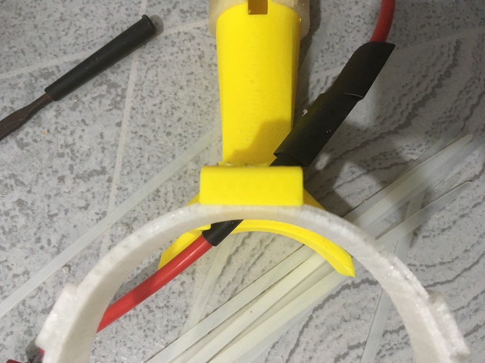
Pull the 3D printed cover down on top of the DN80 and zip-tie it in place, now leave it until the silicon is dry.![]()
Slide the shrink rap tubes down to cover the wire all the way down to the black sensor box and use hot air to shrink them in 3 layers on top of each other.
Take the 2 M3 nuts and bolts and add the cable gripper, this stops the wire getting pulled out of the sensor and braking or braking the waterproofing.
Solder the wire end of the aviation connector to the main cable. I put pin 1 as red, pin 2 as yellow and pin 3 as black. Put the connector back together.
-
3Build the battery box & Aduino hosing
Download the wiring diagram from the files section.
Solder the power wires to the bottom of the Arduino first. Then put the TFT display onto the Arduino.
Put the housing side of the aviation connector into the housing and lock it in place with the screw thread.
Put the power switch into the housing as well (it will simply snap into place).
Put the TFT display and Arduino into the lower housing being careful to find a good path for the power wires.
Put the battery holder into the lower housing (it will be loose until you put the upper housing in place and screw it down).
Now solder the wires together as shown in the wiring diagram.
Check all your connections.
Put the upper housing on top and move the battery holder in place so everything lines up.
Screw the top down with 6 wood screws.
Put in a battery.
Link the sensor up and power on the unit.
Open Flow Meter
An Arduino powered flow-meter for use in geography river studies and environmental monitoring projects


Discussions
Become a Hackaday.io Member
Create an account to leave a comment. Already have an account? Log In.