Close
0%
0%

6809 SBC

A 6809-based SBC with DES encryption hardware.

Similar projects worth following
While at school in the early 80's I built a 6809 computer that had been published in a computer magazine, one board at a time. Limited funds slowed progress, and by the time the first PC's arrived I still didn't have a fully working computer. This project is an attempt to make a working system from slightly more modern parts to finish what I started nearly 40 years ago.
The target is to have a euro card-sized computer running Flex from a CF card, serial interfaces, plenty of RAM and a small expansion connector. Nothing that hasn't been done many times before, but this will be all my work.

Earlier in the year I build a Rosco 68000 computer board, which re-ignited my interest in home computing from the days when home computers were quite simple. I also found a source for MC6859 DES encryption chips (which I remember reading about in the early 80's), and a plan started to form. I soon found the Grant Searle web pages and then the blog pages byJeff Tranter, and I was hooked. 

A 6809 computer running Flex or similar was a realistic target, and relatively modern components mean this can fit on a single PCB. 74HC logic eliminates the need for lots of buffers, large memory chips are cheap and Compact Flash is a practical floppy drive replacement.

I'm sharing all of the files for this project as I go, as well as a commentary on my progress, so hopefully the process will be of interest to some people. 
DSKviewer.m

m - 4.22 kB - 06/09/2022 at 11:04

Download

CF_Test.asm

asm - 14.38 kB - 03/19/2021 at 14:35

Download

6809 EXPANDED V4 SBC p2.pdf

application/pdf - 29.06 kB - 01/31/2021 at 17:29

Preview

6809 EXPANDED V4 SBC p1.pdf

Adobe Portable Document Format - 37.66 kB - 01/31/2021 at 17:29

Preview

  • 1 × MC6809E Microprocessors, Microcontrollers, DSPs / Microprocessors (MPUs)
  • 1 × MC68681 Microprocessors, Microcontrollers, DSPs / IO Controllers
  • 1 × MC6859 Application Specific ICs / Telecom ICs
  • 1 × RTC72421 Clock and Timer ICs / Real-Time Clocks
  • 1 × AS6C4008 Memory ICs / Static RAM (SRAM)

View all 29 components

  • Creating a Flex disk image

    Phil.macphail09/10/2024 at 14:38 0 comments

    This turned-out to be more involved than expected as the USB serial interface seems to introduce extra characters that need to be 'flushed' with each command sent when using Octave serial control. I don't know if this is an Octave feature, USB interface feature, or an interaction between them, so anyone replicating this may get different results.

    I have a set of CF Card commands in the EEPROM that let me download a sector image and write a block of memory to a specified part of the CF Card, so it should have been a small step to do this from Octave rather than the terminal. Using a modification of the Flex Octave utilities discussed previously I read a disk image and wrote it to a CF Card, where the sector number was used to set the LBA0 value and the track number set the LBA1 value. With this I can replicate any disk image on the CF Card. This gives me an image that can be used to write the disk drivers for Flex. Should anything go wrong then a new image can be created easily enough.

    The program to do this is called FlexSectorWriter.m and is available on GitHub here https://github.com/valgamaa/6809-SBC

    The process of creating a disk image is slow but doesn't need to be done often, and the resulting image appears to be a true image of the original file. This lets me now work on the disk drivers, when time permits.

  • Flex (half)working

    Phil.macphail04/29/2024 at 09:37 0 comments

    Although it has.been a while since I last posted an update, the project is still alive. The log summarizes all that I have been doing in the last year

    The DSKviewer code produced a directory listing of a Flex disk image, however the formatting was messy and that made reading the output more difficult than it could have been. I  added a formatting function to the code to fix this, and placed the new code on GitHub here.

    I had planned to boot Flex from the CF card just like it would have been done in the days of floppies, but realised that the memory area Flex is placed in is within the range covered by my PROM. The PROM is copied to RAM then disabled after reset, so there is no reason not to put an image of Flex in the PROM and have an ‘instant-boot’ Flex computer, so that is what I (eventually) did.  Of course,  there were a few complication along the way.

    Based on the DSKviewer code I had previously written, I wrote a program to extract the sectors for any chosen file, which can then be processed further. The first sector of a SYS, COR or CMD file starts with the following information -

       Byte 0 Next track (or 0 for last sector)
       Byte 1 Next Sector (or 0 for last sector)
       Byte 2 Most significant byte of number of sectors in the file
       Byte 3 Least significant byte of number of sectors in the file
       Byte 4  ($02)
       Byte 5 Most significant byte of the load address
       Byte 6 Least significant byte of the load address
       Byte 7 Number of data bytes in the record
       Byte 8-n Binary data

    What should be noted, however, is that the data can span sector boundaries - only the first sector is guaranteed to start with this information. It is quite a simple process to take the address and data fields and convert them into s09 records, although one line in the flex file may require several s09 lines. The code FlexExtractor writes an s09 file to disk that can then be downloaded to the SBC.
    I processed a random flex.sys file with this code and downloaded it to my computer, which promptly froze. Looking at the s09 file I could see that the drivers for the original computer were located in the same space as my monitor, so I edited the s09 file to remove them and tried again. I already had the terminal IO code in memory, so used G CD00 to jump to the start of Flex. This is what I saw on the terminal -

    ASSIST09-Flex
    :G CD00
    @
    FLEX 9.0

    DATE (MM,DD,YY)? 28,04,24

    DISK ERROR #
    +++

    As there were no disk drivers installed this is what i expected, so I now have Flex half-working on my computer. With the disk drivers installed and a formatted CF card I will have a working Flex computer.
    With this success I searched the archive of Fles disks to find .COR files rather than .SYS, trying each in turn until I found the most up to date version of Flex I could. I found a 9.1 version, and tried programming this into EEPROM where I ran into the next challenge.
    The srecord program can combine multiple files into a single file suitable for my programmer. I could combine the Assist09 monitor and terminal drivers happily, however the s09 file for Flex caused errors. The .COR file contains patches applied to earlier code, and therefore had repeated data for fixed addresses. That's fine in the original use case and when downloaded to RAM, where memory contents can be changed any number of times before code is executed, but not for PROMs. I wrote another Octave program (SRecordFilter) to read an s09 file and recreate the memory map. This gave a final image of the memory that could be sorted into ascending addresses and written back to disk. The sort used was a simple bubble-sort so the process is slow, but only needed once.
    With this the three pieces of code could be combined and the EEPROM programmed. 
    I now have a computer with Assist09 working, which can switch to Flex when wanted so I now need a formatted CF card to go further.

  • Flex .DSK file format

    Phil.macphail06/09/2022 at 11:01 0 comments

    I found an archive of Flex software at this website https://www.simonwynn.com/flex which was the missing link for me. I had been looking for the Flex operating system for a while, and had slowed work on the SBC due to lack of success. This was more than I hoped for, and started to look at the archive in detail. My first question was what is the format of the .DSK files? There is some information on the web, but thought it best to work it out for myself. It turned-out to be quite simple, and I can see a way to transfer images to my computer in quite a simple way. But first, the investigation process. I read a .DSK file into Matlab which gave me an array of single-character data. I checked that the size of the array was a multiple of 256 (a Flex sector) and it was, confirming the file contains a raw image of a disk. The process of ‘reconstructing’ the disk in Matlab was a simple sequence of steps -
    1. Reshape the array into n by 256 entries. This gives me an array of sectors that can now be examined to find the number of tracks and sectors on the original disk.
    2. Track zero, sector 3 of a disk contains the System Information Record (SIR), and bytes $26 and $27 contain the number of tracks and sectors of the disk. This information is contained in the 3rd sector in the array created by step one, and extracting this information means the array can be reshaped again to give an array that can be indexed as Disk(Track, Sector, Data).

    Having an array that mirrors the physical layout of the original disk now permits the directory to be read. Track 0, Sector 5 is the first directory sector, and the contents of the sector are outlined here http://www.waveguide.se/?article=reading-flex-disk-images. It was quite simple to decode the directory, print it, and check to see if it overflows onto another sector, when the same process can be repeated. I am now able to view the directory of any disk image, and select one with Flex on it to copy to my SBC.
    I have uploaded the code here, and it should work with GNU Octave with minimal changes, although I haven’t tried.
    The next steps.
    It should be quite simple to extend the Matlab program to send a sector to the SBC, then instruct the SBC to write them to the CF card. I can already set the LBA address, write and verify a sector, so this is quite a small step. Repeating this for all sectors will therefore transfer a disk image to the CF card. With this done, I should be able to then modify the Flex code with my routines and give me a working Flex computer. Getting closer, but still quite a bit to do.

  • Getting ready for Flex

    Phil.macphail04/24/2022 at 09:51 0 comments

    Until now I have been using the Windows application for the TL866 Ⅱ+ programmer, but as I use a Mac it was inconvenient. I had read about a command-line application for this, and now seemed like a good time to investigate. Using Homebrew, I installed minipro and was able to read an EEPROM, copy the contents, erase and reprogram the PROM. 

    The next test was to take the Intelhex file from A09 and program that. Unfortunately that generated an error message that multiple values were assigned to the same address, and when I looked at the file I could see that it was true. A09 seems to generate an extra line at the start of the file that duplicated a later part of the file. Deleting this removed the error message, but the contents of the PROM were all FF's. The code starts at $8000, so how to tell the programmer this? It turns out you don't, another program called Srecord does this instead.

    Srecord is a really useful program that can manipulate Intelhex and s-record files in any way imaginable. With this I could add (or rather subtract) an offset to the file so that it sits within the $0000-$7FFF range of my PROM, without modifying the data, so that minipro would program the PROM correctly.

    With the new programming method working it was time to move-on. I modified the Assist09 monitor to add the CF card routines, and added a command (Z) to invoke them. I also added a Flex boot command (F) that reads track 0, sector 3 from the CF card and places the data at $C100. It then jumps to this address. I reprogrammed the PROM and used the CF card utility to write 3 bytes to the start of Track 0, Sector 3 that jumped back to the cold-start address of the monitor. Executing the F command without a CF card installed crashed the computer as expected, and repeating this with the CF card installed resulted in the monitor restarting. Success.

    I have also written the drivers needed for Flex, and added them to the PROM. Once more Srecord came in handy, as it will merge multiple files into a single one for programming. I need to do a bit more testing of these routines before trying to configure Flex but I have worked-out how to get the data I need onto the CF card to do this. I will post another update on this soon.

  • Compact Flash utility finished

    Phil.macphail03/19/2021 at 14:34 0 comments

    The Compact Flash utility produced several lessons for me, but I now have a version that I’m happy with. I bought a few 32M cards on Ebay to use as test-cases - it wouldn’t matter if I broke them, and they contained data which would help with checking the sector reading code. This proved to be a mixed blessing as, no matter what I tried, I could only read or write 511 bytes to the cards. I spent a couple of weeks trying different code implementations but they all behaved the same. I could write 512 bytes to the card, and read 512 bytes back, but the last byte was always corrupt. In desperation I tried a new 2G card, and it worked perfectly! I really have no idea what the problem is, but it is with these second-hand cards rather than my code. From a practical point of view they will still be usable as Flex uses 256-byte sectors, and I will fill the rest with $00 when writing, and ignore the ‘extra’ when reading. I have added the stand-alone code to the files section here, and will merge it with Assist09 to simplify programming the EEPROM.

    ? - List the commands available.

    A simple text list of the available commands.

    D - Display the RAM buffer contents.

    A 512-byte buffer is held in memory, where data read from the CF Card is stored. Calls to the memory dump code in Assist09 displays the data,16 bytes to a line. The buffer starts at $1000 so the sector data address is offset by the same amount. This saved quite a bit of code, so seems like a reasonable compromise.

    F - Fill CF Card buffer with a constant.

    A two-digit hex value is read from the terminal. If a wrong key is pressed then the number is discarded and input starts from the beginning.

    I - Initialise the CF Card.

    When this program runs nothing is done to configure the CF Card interface. This command sets the card for an 8-bit interface and LBA addressing. This command must be run before reading or writing to the card.

    L - Set the LBA address.

    At startup the LBA address is set to $00 $00 $00 $0. This command lets the user navigate to any part of the CF Card.

    R - Read a data block from theCF Card.

    The 512-byte sector pointed to by the LBA address is copied to the RAM buffer, and can be viewed with the ‘D’ command.

    W - Write a data block to the CF Card.

    The RAM buffer is written to the sector pointed to by the LBA address.

    V - Verify the data block written to the CF Card.

    This command reads the sector pointed to by the LBA address, and compares each byte with the corresponding one in the RAM buffer. Any errors are reported with the address of the error, data read and value held in the buffer.

    P - Print the properties of the CF Card.

    The model number, serial number firmware revision and size of the card in terms of LBA values is reported.

    Q - Exit this application & return to the monitor.

    Returns to the Assist09 prompt.

    The monitor can be used to modify the buffer contents if desired, then the application re-run to write the updated values to the CF Card.

    With the listing uploaded here, the code can be downloaded to RAM using the L command in the monitor, and executed with C 2000.
    The next steps are to consolidate this code with Assist09, and either write some test code for the 6859 or start on the Flex drivers.

  • New PCB, new bugs (but very minor)

    Phil.macphail02/27/2021 at 18:45 0 comments

    The new PCB arrived before the Chinese New Year holiday, and I even found time to assemble one. All the modifications listed in the previous logs worked without problem, and I was able to get the monitor prompt straight after reset. The real-time clock circuit is new, and I very quickly noticed a missing connection - one of the CS pins is floating and should be connected to the reset line. With this fixed with a small wire the chip could be read and written to, but to use it properly needs a little more complex code, so that can wait. The code for the CF card isn’t finished yet but is moving forward. I can read the card details into a buffer and list them calling the memory dump routines in the monitor. I can also fill the buffer with a constant and read a block from the card. The reads aren’t consistent, however, so I want to fix this before writing to the card. I did notice that the configuration data seems to be a little scrambled, configured for Intel-style 16-bit reads. Reading 8 bits at a time, the LSB of the address needs to be inverted. Without this, the manufacturer for the card I have is reported as OTHSBI A, rather than TOSHIBA.

    A kind reader correctly pointed-out that the TSC pin is floating in my design, and it should be grounded. Another wire again fixed this, but I had been lucky that the chips I used (all Thomson) seemed to ‘float-low’ on this pin and work. I had noticed that at power-on the CPU required a press of the reset button to work, and assumed this was due to how the PSU ramped. That is one of the reasons I added the reset chip to the new design. 
    My priority now is to finish the CF Card code, then write the routines for I/O for Flex. Actually getting Flex onto the CF cards is something I haven’t yet resolved, but that isn’t a concern right now.

  • Compact Flash Card Interface Works

    Phil.macphail01/31/2021 at 17:28 0 comments

    The Compact Flash interface was quite easy to check, however plugging a CF card into the socket before power-up prevented the whole computer from starting. Something as major as that should be easy to diagnose, and so it was. The CF Card is configured at reset by checking the status of the two select pins in the interface, and the first problem was that the reset wasn't connected to the interface.... fixing that didn't help much, however, as the two select pins were swapped. With that fixed the computer started and I could start to write a program to read and write to the memory card.

    Assist09 provides several functions that are handy when writing a program, such as read a character from the console, print to the console and print memory locations. Software interrupts control this and I soon had the bare bones of a disk editor working. I will continue to improve this over the next week or two, but I could see enough to know the hardware was working correctly. With the Chinese New Year getting close I added all the changes to the PCB and added a few features, and sent the board off to be made.

    The new PCB has a few new features an addition to bug fixes. I have opted for a better reset circuit as the simple resistor, capacitor and push-button switch isn't so good for any chips that don't have Schmitt-trigger inputs (and I can't be sure the signal met the CF Card specification). A small expansion connector will let me add features in the future without making a whole new card. I would like to add a video and keyboard interface in the future (and a second CF Card socket), and this expansion port will let me do this. I was also able to squeeze a real-time clock chip onto the board too, with the thought that, should I get Flex running, I can use this to set the date.

    Quite a successful couple of weeks, and I hope I have time to complete the CF Card editor before the PCB's arrive, so that I can put it in the EEPROM along with the monitor. With the design becoming pretty stable now I have added a parts list for the new design, and added the schematic too.

  • MC68681 - Just one more thing...

    Phil.macphail01/13/2021 at 17:58 2 comments

    Configuring the 68681 serial ports was the next task, so that I can replace the 6850 I am currently using. The datasheets from NXP and Motorola rather complicate things with the register explanations requiring constant referencing to different pages to do quite simple things. I decided that I would write a simple program to send a character from port A repeatedly as the first test, so that I could confirm the correct configuration. This proved problematic but I found a configuration that almost worked, so I enhanced the code to read a received character and resend it. I could then check the function in a controlled way. With this some characters were sent correctly, some were modified to different characters, and some were translated to multiple characters. This was completely repeatable; pressing the same key on the keyboard always resulted in the same outcome, even if it was incorrect. Checking with an oscilloscope I could see that the data format being sent wasn’t what I was setting in the configuration registers, and I suspected a hardware fault. When I designed the PCB I didn’t gate the chip select pin with the E signal from the CPU as I didn’t have a spare gate. I half expected that to cause a problem but I had seen other schematics that did the same thing, so thought I would try it. I was fairly sure that might be the problem here. Piggy-backing a chip onto another and lifting a couple of pins let me add the required gate, and everything started working as expected. Fortunately the gate I need will be available when I stop using the 6850, so the changes to the layout are quite simple (but the changes for the revision of the PCB are growing). I also realised I had the pinout of the serial connector wrong to plug an FTDI serial board straight into the CPU board, so more changes needed there too.With a reliable serial port working with my terminal I had all the routines needed to modify the monitor code. I was able to transfer all communication to the 68681, set the memory page register, copy the EEPROM to RAM and disable the EEPROM (using the output pin of the 68681) in a single update to the monitor. It all worked in the same way as the individual steps had, but this was the first time they were all tried at once. Very satisfying. Having the 6850 and Assist09 working from the (almost) beginning was a huge help in getting this far. Without that I don't think I could have got the new serial interface working at all as I would have had little insight into the behaviour of the PCB otherwise.
    The next step is to apply all the modifications to a second PCB that has a Compact Flash socket in place of the 6850 and test the CF interface. If this works then it will be time to get a new PCB made with all the changes and add a few more features.
    I will put the asm file for the modified Assist09 on the GitHub page in the next couple of days, and probably add it here too.

  • Further functional checks

    Phil.macphail01/10/2021 at 19:17 0 comments

    With the computer running code correctly I could start to verify the other features of the design. The upper 32k of the memory map has both RAM and ROM in parallel. Writes to this space go to the RAM, but reads come from the ROM after reset, however the ROM can be disabled so that reads come from the RAM. This is important if I want to run Flex, as I need RAM at the top of memory. Reset set a 74HC74 used as a SR flip-flop, and the output of this is used to gate the chip-select signals, diverting reads to ROM. Writing to a memory location resets this flip-flop, so this is easy to test. Using the monitor to write to $F2C0 crashed to computer, and I could see with a logic probe that the ROM wasn’t selected at all. Now how to continue correct program execution? This turns out to be quite easy. Re-assembling the Assist09 code to produce a S-record output gave me a file that I could download to the SBC using the Assist09. True bootstrapping! This gives identical memory contents in both RAM and ROM, so switching between them should be invisible to the CPU. Writing to $F2C0 once more didn’t crash the processor, and I could read, modify and verify memory contents that were previously located in the ROM space.The second memory feature is that the space $D000-DFFF is mapped to any 4k block through the 512k of the RAM chip. With the ROM disabled I could now ‘see’ this space, and see if it works. Again, the monitor let me do this very quickly. The sequence used was

    • Writing a page number to $F280 then writing something to $D800
    • Write a new page number to $F280, and write different data to $D800
    • Write the original page number to $F280, and examine the contents of $D800, to verify that it is the original data written in step one.
    • Write new data to $F800
    • Write the second page number to $F280
    • Verify the data at $D800 corresponds with the data written in step two.

    This all worked perfectly, so for now I can confirm that the memory paging is working correctly. All good so far, and no need to write any code so this all took less than an hour. The only thing left to verify was the 68681, and again I could do initial checks with the monitor.
    The PCB has two LED’s connected to the output port of the 68681, so writing to the correct register should be able to turn them on and off. Again, the monitor made this simple and I could control the LED’s as expected. At this point I realised that the state of these outputs is defined at reset; I could use one output to control the ROM select, so that I can switch it in and out as required rather than just at reset. Removing the 74HC74 and soldering a wire on the underside of the board took a few moments, and worked perfectly.
    This was all going too well, and it was at this point that I realised I couldn’t check the DES chip - it requires a clock input at twice the bus frequency, and I had connected this to the crystal oscillator running at four time frequency. This will require a bit of surgery, so perhaps I will leave this for now.

  • First signs of life

    Phil.macphail01/03/2021 at 14:22 0 comments

    After assembling the board I programmed the EEPROM with a version of Assist09 with the ACIA address modified to reflect the new memory map. On power-up nothing happened. This isn’t entirely surprising but was worth a shot, it would have been great to see the prompt on my terminal. Assist09 uses a vector map placed in RAM, so to function correctly both memories need to be working correctly; I needed to see where the problem was. I considered jamming NOP instructions on the bus to check the processor was functioning, but the 6809 sets the address bus to $FFFF when executing instructions so it isn’t easy to see anything useful with this. Instead, I wrote a small piece of code that simply jumped to itself. This would exercise the EEPROM only, and it worked fine. The problem was therefore with the RAM.

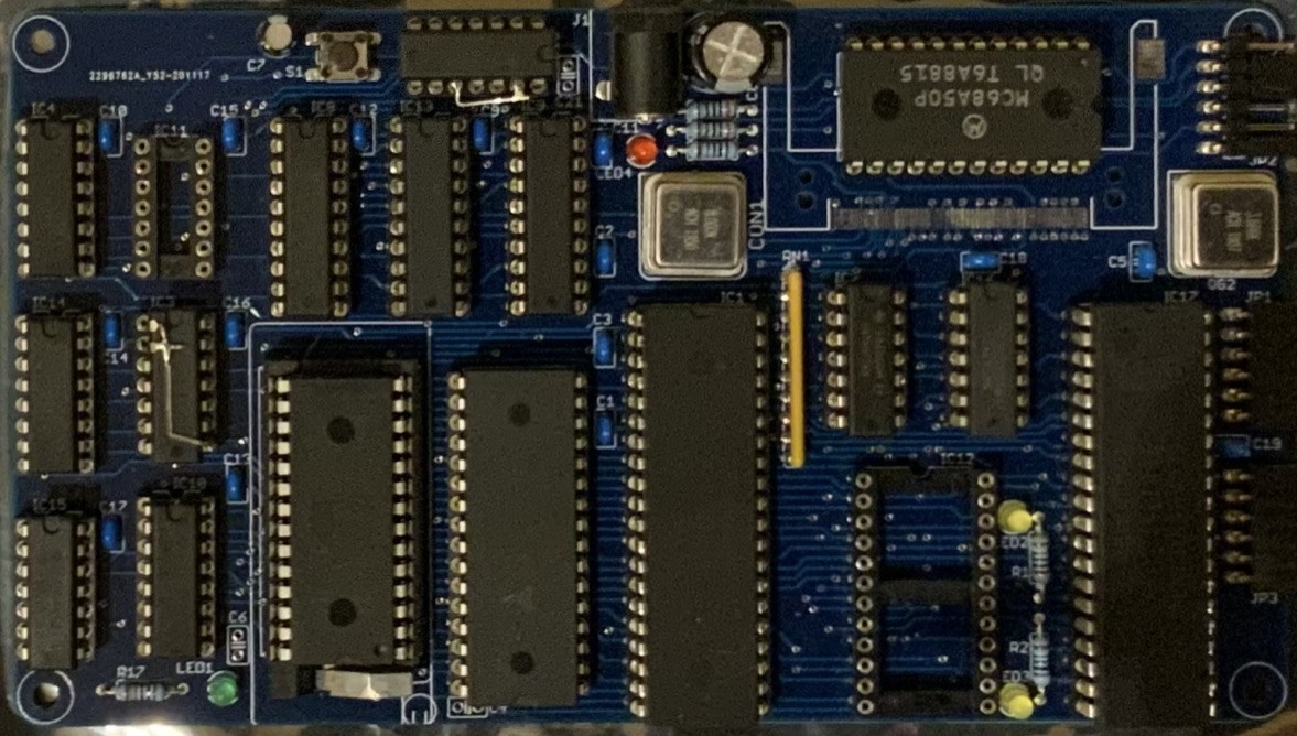
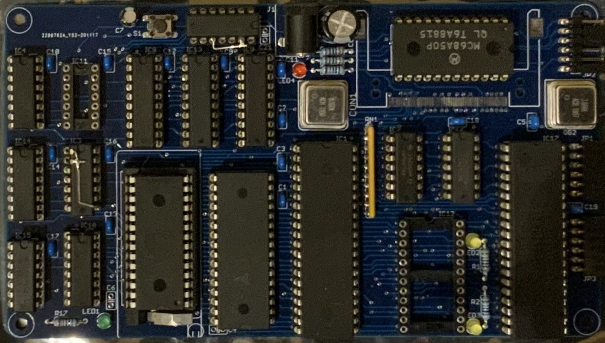
    I wrote another short piece of code that wrote to a fixed memory location in an endless loop, and I could see the correct data on the data bus synchronized with the control signals for RAM. This indicated that the problem was with reading, so another piece of code read from the same location in a loop. I could see straight away that when the read cycle started the RAM was disabled. I had just re-invented the write-only memory! Fortunately I was able to modify the circuit using the gates on the board (as seen in the photo) and both reading and writing worked correctly. That should be enough to get Assist09 running.

    Reprogramming the EEPROM with the monitor still didn’t give me a prompt on the terminal. What could be wrong? I could see the ACIA being polled regularly so the code was running correctly, so what had changed? When I reset the board I could see that the ACIA transmitted something, but the terminal didn’t recognize it. I had switched from a 7.3728MHz crystal to a 3.6864MHz so expected the Baud rate to halve. What I realized later was that on the previous board the ACIA was clocked by the crystal frequency divided by 4, so my new design was actually running at twice the speed of the previous design. Changing the settings on the terminal program finally gave me the Assist09 start-up text and command prompt. With Assist09 running I can download code rather than reprogram the EEPROM so progress should be much easier.

View all 13 project logs

Enjoy this project?

Share

Discussions

hanshein wrote 09/01/2024 at 11:14 point

Hi, I found the s09 files on github, however do you also provide (asm) source code files? Thank you for this project, I owned an 6809-Eurocom-2 from Eltec fourty years ago and I am very tempted to rebuild your design :-)

  Are you sure? yes | no

Phil.macphail wrote 09/10/2024 at 14:16 point

Hi Harshen, thnanks for your comment, I will add the asm files this afternoon.

  Are you sure? yes | no

hanshein wrote 09/11/2024 at 14:14 point

Thanks a lot! (checked that Assist09 already patched for 68681! Thank you!)

My status:

- ordered PCB at aisler.net with github files

- found 6859 at tvsat.com.pl

- 68681 was a nightmare, not available in Europe. Use Aliexpress or amazon.com (as a German I am using amazon.de, there the 68681 is NOT available)

- RTC72421 via aliexpress.

- intend to use HD6309 (in 6809 mode), currently easier to obtain than a 6809

- half size oscillators not so easy as expected(!), however medium availability.

  Are you sure? yes | no

Nick Brok wrote 03/29/2022 at 13:04 point

Hi Phil, I found some issues with your CF-card software also but it helped me to write a little OS for the 6809. It works, but isn't ready for publication yet. For others to take part of it I published it on github. Only one slice (of 1.3MB) is supported due to a shortage of memory. (The OS resides from $8000-$BFFF) I use a buffer of 4KB for the directory and this consumes a lot of memory. I would be happier with a complete FAT12 or FAT16 based software written in assembly-code. I can give you the working CF-card software part back, that is working and tested. I use my own monitor so the I/O calls looks different then yours. It is part of the OS I wrote. You can find it here: https://github.com/nbrok/DOS09/blob/main/cfcard.asm

  Are you sure? yes | no

Phil.macphail wrote 03/29/2022 at 13:22 point

Hi Nick, what were the issues you had? A quick look at your code doesn't show much - just a JSR swapped to BSR. It would be interesting to see if I can improve on what I have.

  Are you sure? yes | no

Nick Brok wrote 03/29/2022 at 13:50 point

It is in the CF-init part and the CF-info. This code generates in HEX the correct value of sectors available... At the end of cf-init I added a call to datwait, so the card has time to finish the initialization. Also the initialization wasn't in the correct order, I have fixed it.

  Are you sure? yes | no

Phil.macphail wrote 03/30/2022 at 13:43 point

That's interesting, when I try your config code then look at the CF-info I get this -

    Model No.: j xxhh
Firmware Rev.:  
   Serial No.: 2-1T6l  s..      
    LBA Size : 32 30 30 34 

but with my original code I get this, which is correct

    Model No.: STI Flash 7.2.0                         
Firmware Rev.: 02-10-06
   Serial No.: STI J105105244104050
    LBA Size : F5 00 00 00 

These STI cards have problems when reading and writing (but Toshiba cards are fine, including CF-info), but if I use your config, then mine, the cards seem to work. Have you tried your code with many cards? A composite of our initiation codes might be worth investigating, you are writing $82 to CFFEATURE while I'm not, what does this command do?

  Are you sure? yes | no

Nick Brok wrote 02/25/2022 at 13:56 point

Hi Phil,
If you look at the original datasheet of the 68B09E you can read that TSC must be grounded to work probably.  That it is working in your setup is strange. +5V on this pin sets the 68B09E in tri-sate mode. Perhaps your power supply is making lesser noise then my power supply does. (I use a switching power supply generating 5V). Keeping inputs open isn't a good idea after all. Look at my Scrumpel8d project how I designed it. (also on hackaday). Anyway a nice design of your 6809 computer. I have also written some interesting software for the 6809: Subroutine threaded Forth (nforth09) and a very nice monitor program with a lot of features. I Like your CF-card software, so I have not to event the wheel again.

  Are you sure? yes | no

Phil.macphail wrote 03/29/2022 at 11:55 point

Hi Nick, I'm happy you're finding the software useful, I benefitted from what others had written so it's nice that it is helping others in turn. I have grounded the TSC pin and the reset is possibly a little quicker than before, but hard to tell. Certainly it will improve reliability. 

  Are you sure? yes | no

c.legal wrote 12/31/2021 at 11:57 point

Hi Phil, well I am in Nantes (France) close to the seaside. Basically FLEX (I spent a lot of hours, years ago, to setup FLEX), needs RAM from $A000-$BFFF or more recently from $C000 to $DFFF. You are right leaving half of the SD is not rellay a problem because FLEX adresses only 256 tracks of 255 sectors ... If available, I will be happy to see your schematic before you start an update of your PCB.

  Are you sure? yes | no

c.legal wrote 12/26/2021 at 16:29 point

Hello Phil,

I am interested by the sub project to start FLEX on your harware.

Is there a solution to get a bare board and where are the schematics of the main board ?

Merry Christmas and hope we can work together

Best regards


Christian

  Are you sure? yes | no

Phil.macphail wrote 12/29/2021 at 11:26 point

Hi Christian,

The PCB design is done in Eagle and can be found here https://github.com/valgamaa. I don't have any blank PCB's left but it would be simple to get them made from these files. If you were to do this, however, I would make a small change first by adding a small current-limiting resistor in the supply feed to the super capacitor. I'm happy to do this and update the GitHub files if you wish.

  Are you sure? yes | no

Phil.macphail wrote 02/23/2021 at 18:01 point

Good spot that TSC isn't grounded. I hadn't noticed as the boards have all been working perfectly (other than the issues I have noted in the posts) from the very beginning. I have left then running on my desk for weeks without issue, so I guess you were just unlucky with your design. Without the CPU running reliably I don't honestly see how I could have resolved the initial hardware issues, or made progress with the software, so I wonder if the processor has a pull-down on this pin.

  Are you sure? yes | no

Nick Brok wrote 02/23/2021 at 14:35 point

Does your design work? I think not really, you forgot to connect TSC to ground. TSC turns the 6809E into three state modus. 

  Are you sure? yes | no

Similar Projects

Does this project spark your interest?

Become a member to follow this project and never miss any updates