 Michael Wessel
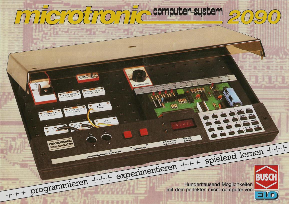
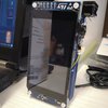
The Busch 2090 Microtronic Computer System was released in 1981 in (West) Germany. It was my first computer on which I learned the basics of (machine language) programming and computer interfacing. This is the original:
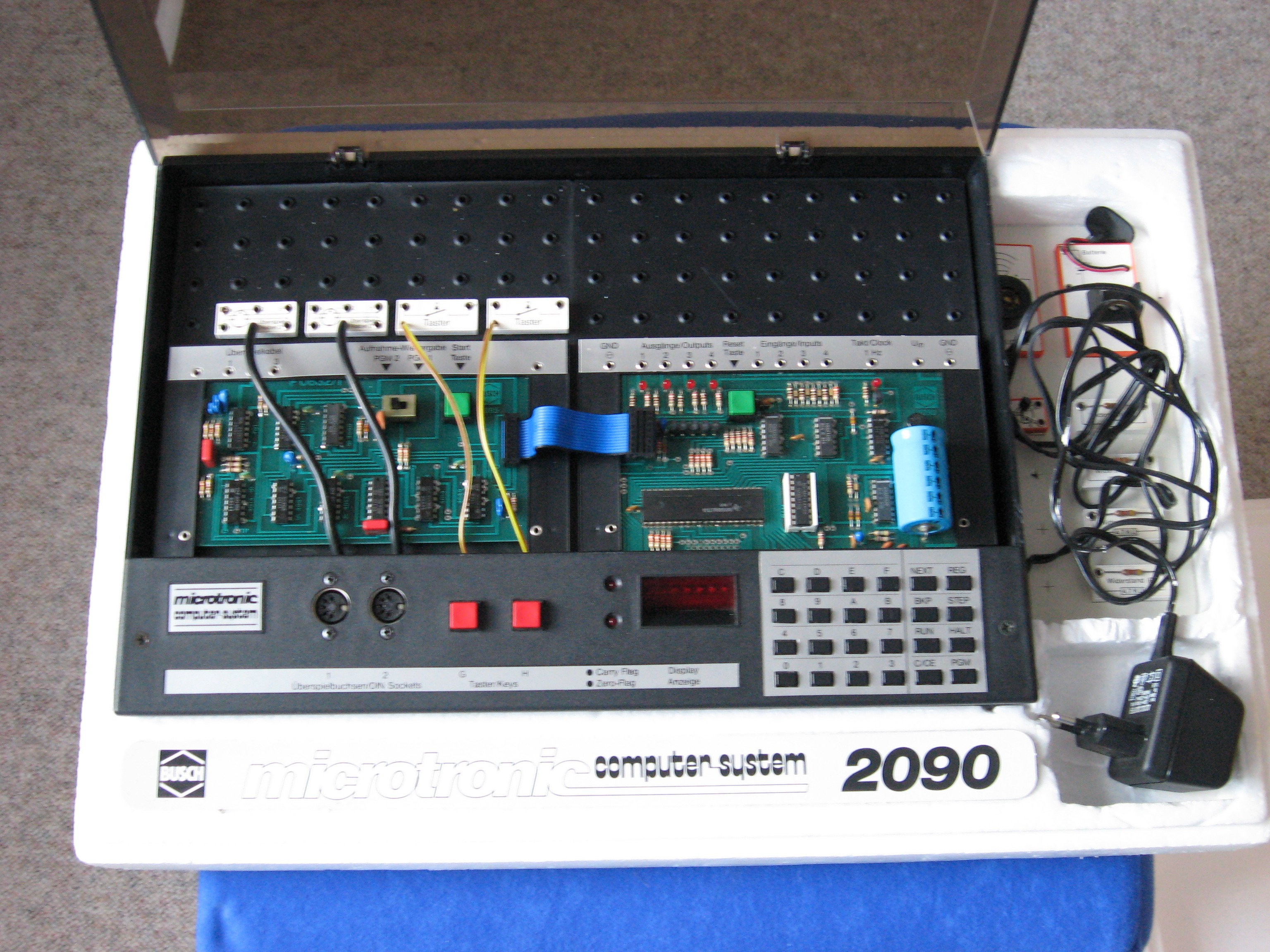
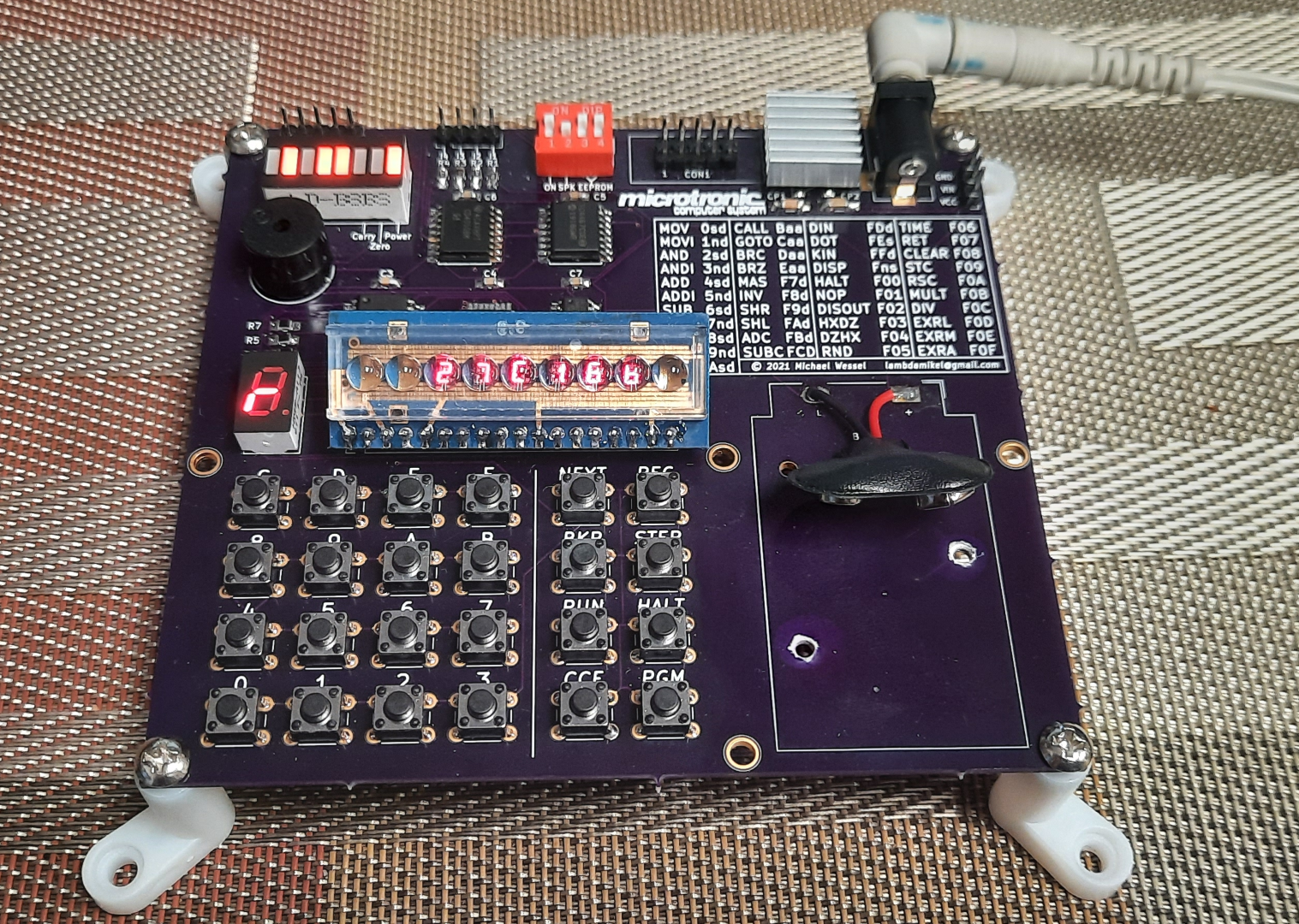
The following picture shows my Microtronic. It was extended with the very rare 2095 Cassette Interface Module (on the left) to allow for cassette tape storage:
In 2016, I had created a talking Arduino-based emulator of the Microtronic system:
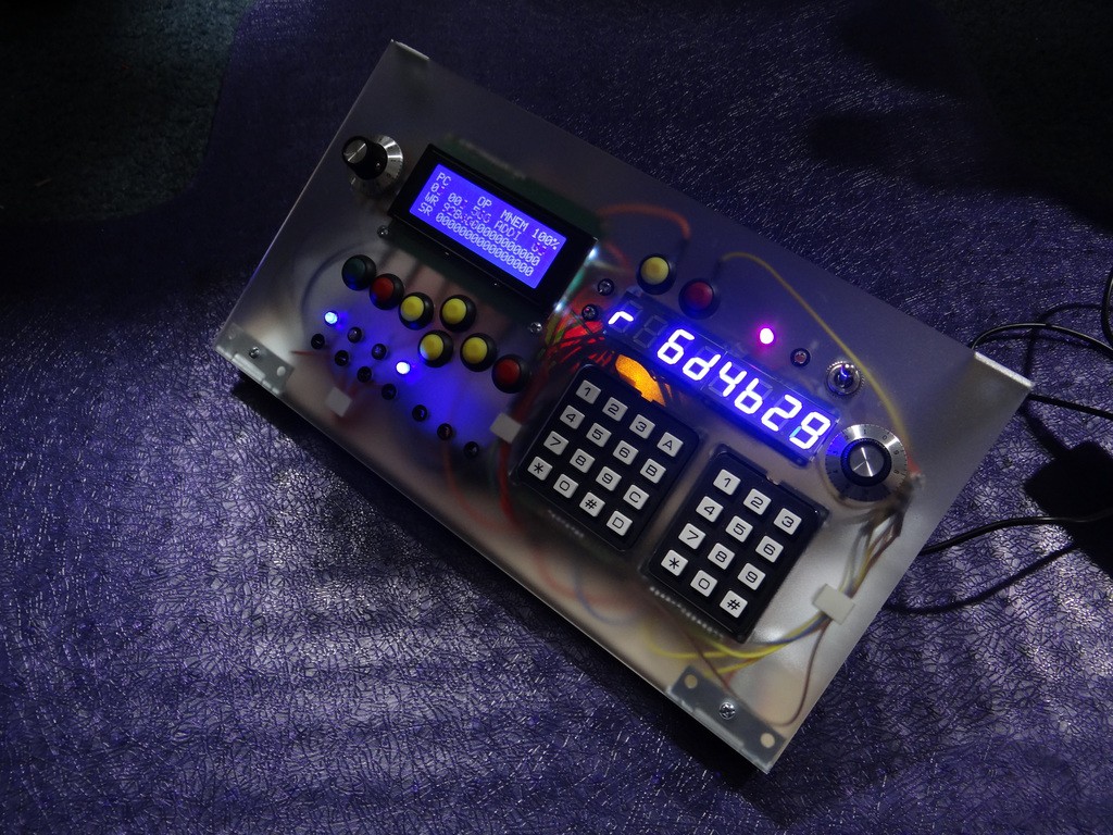
This predecessor project - The Talking Microtronic Emulator - also has a page here on Hackaday. Background info about the Microtronic (i.e., details about its virtual CPU and its instruction set) are provided as well:
https://hackaday.io/project/11560-the-talking-microtronic-computer-system-emulator
Even though the Microtronic uses a TMS 1600 CPU, it was actually not programmed in TMS machine language. Rather, the (mask-programmed) TMS 1600 was running a monitor program that emulated a much more versatile, powerful, and flexible CPU architecture much more suitable for an education system. It even included high-level instructions / op-codes for multiplication, division, time / clock functions, random numbers, display, digital input & output, keyboard input, etc. A very nice instruction set.
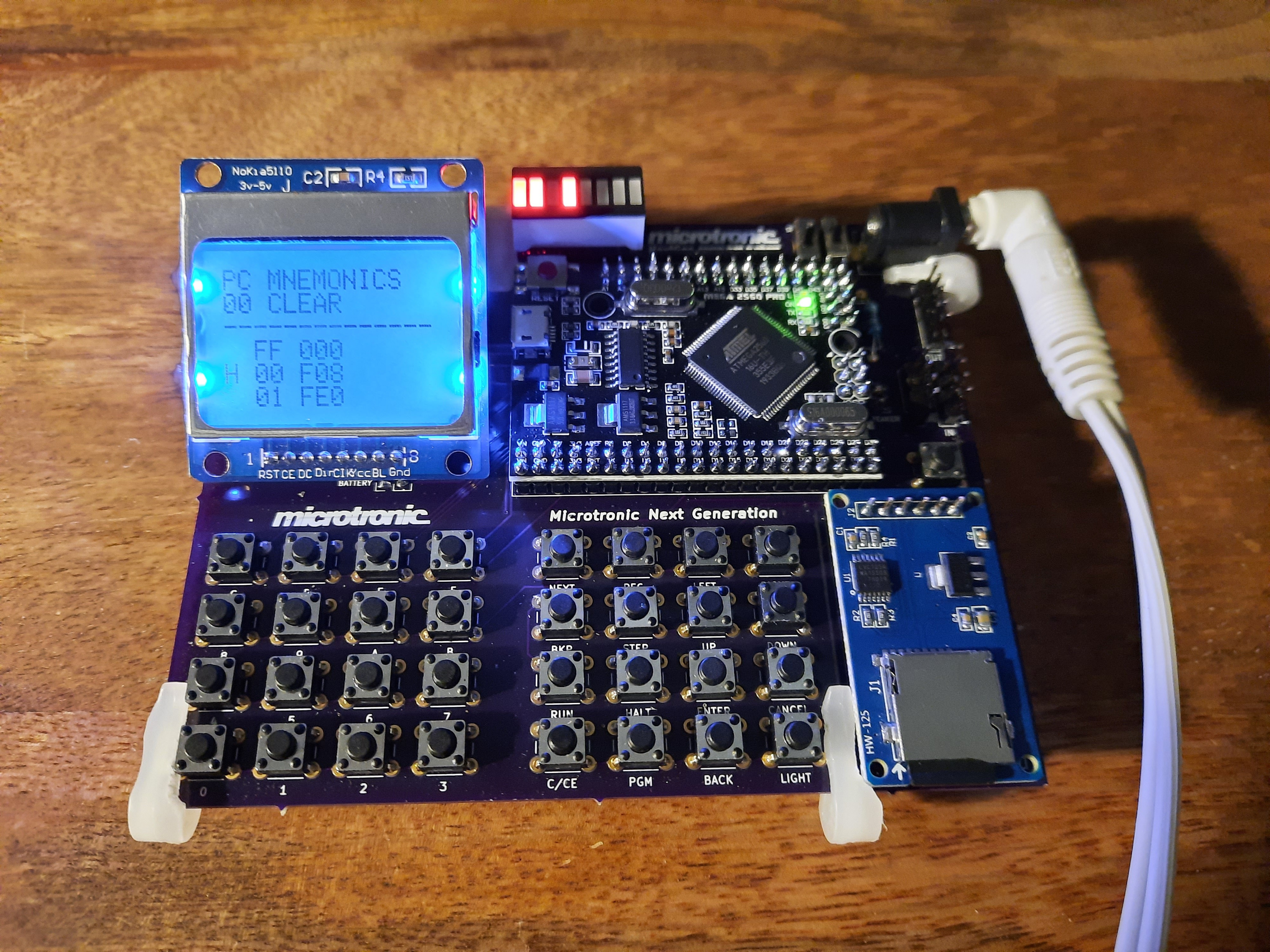
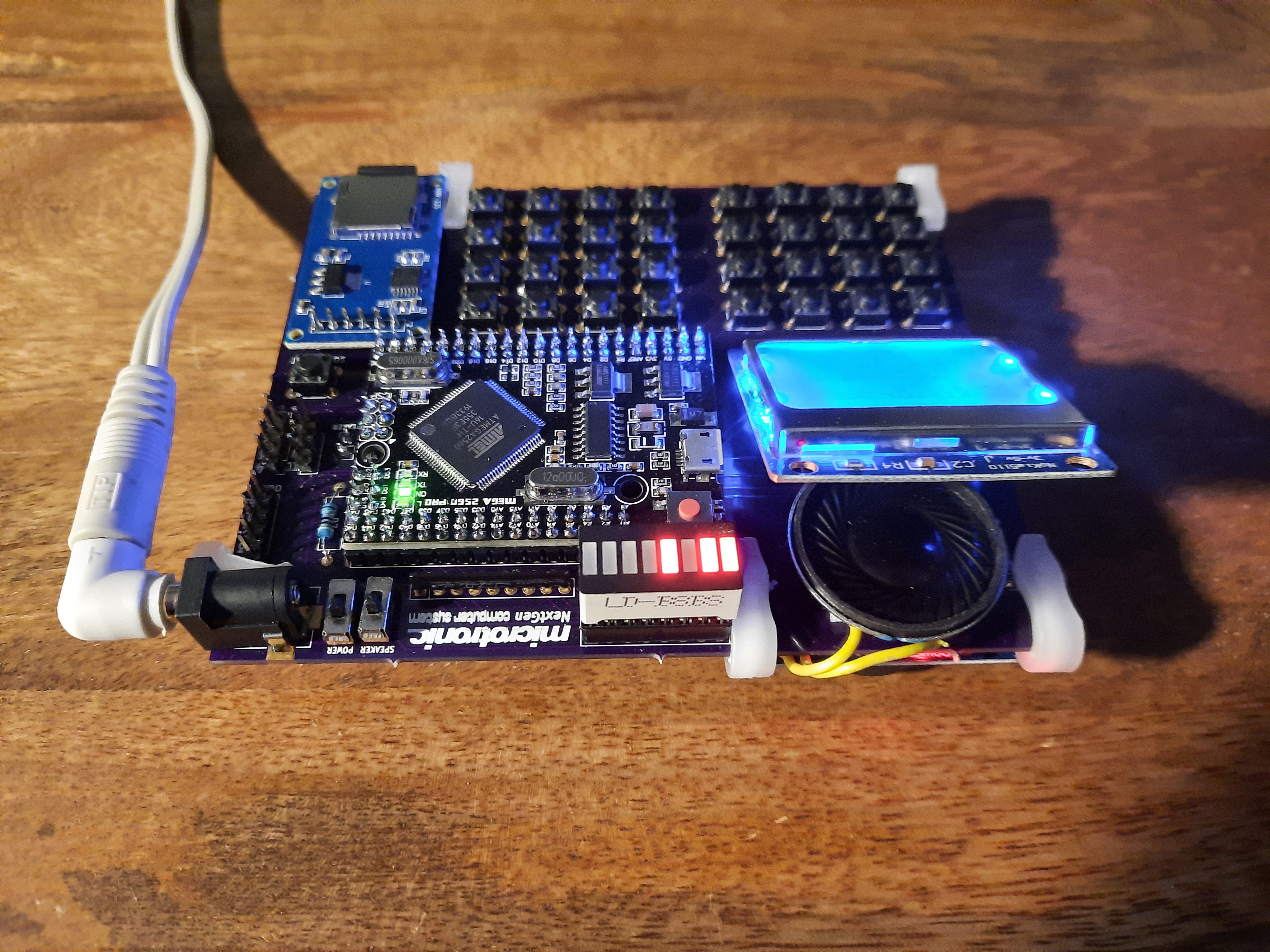
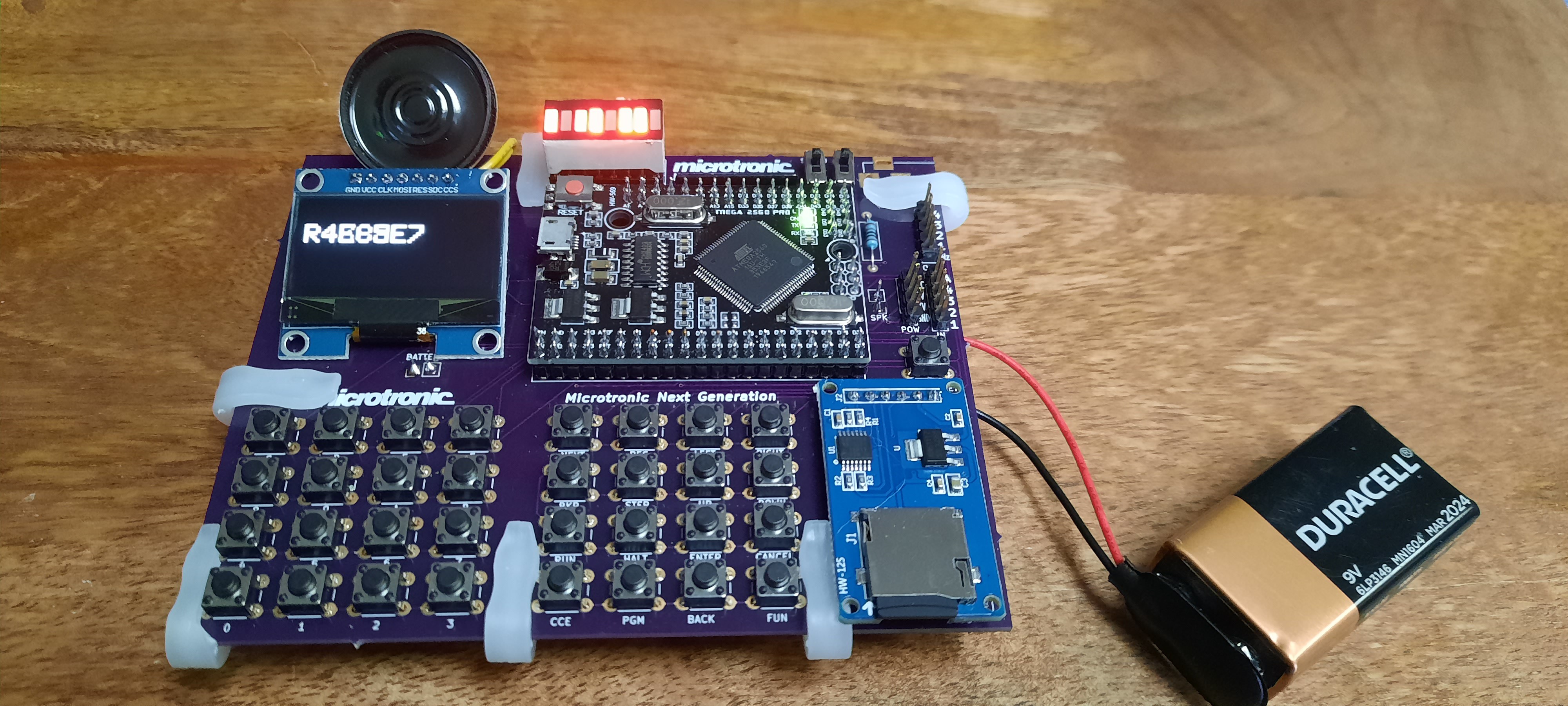
Back to 2020: The Next Generation Microtronic project (these pages) is the continuation, culmination and wrap up of this work. This time, I have a proper PCB with greater reliability and durability than my previous breadboard big-mess-of-wires prototypes, hence preserving my efforts for the future.
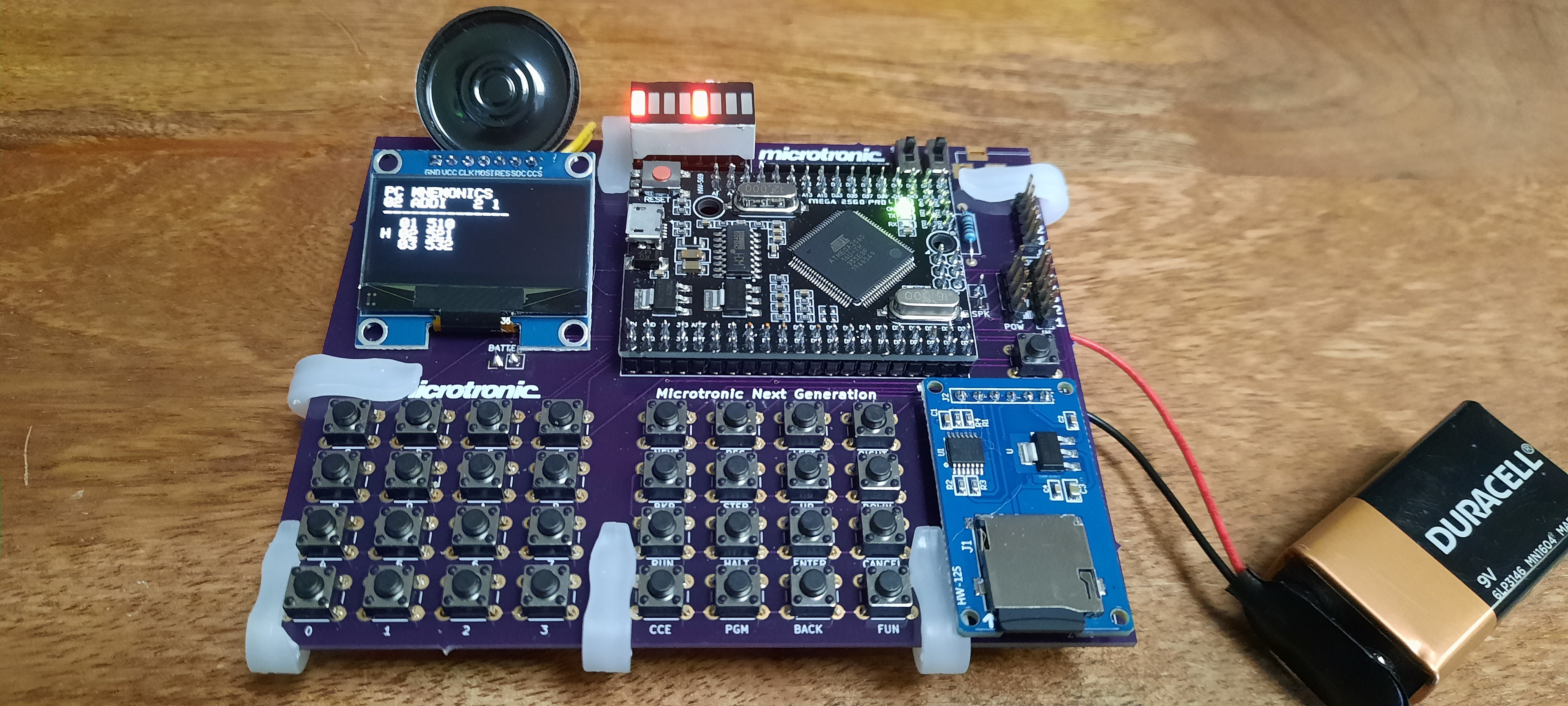
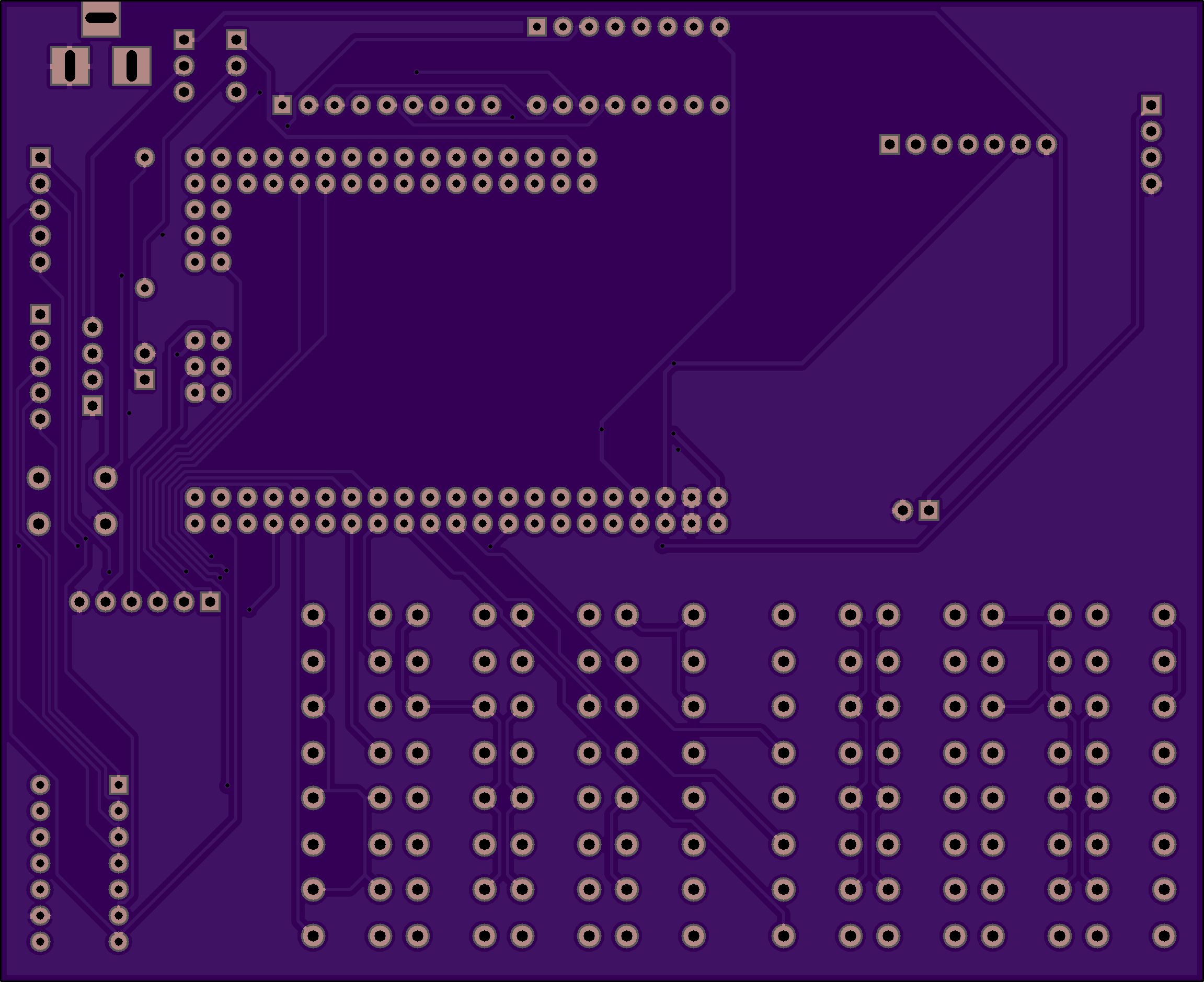
PCB Version 1 for the Nokia 5110:
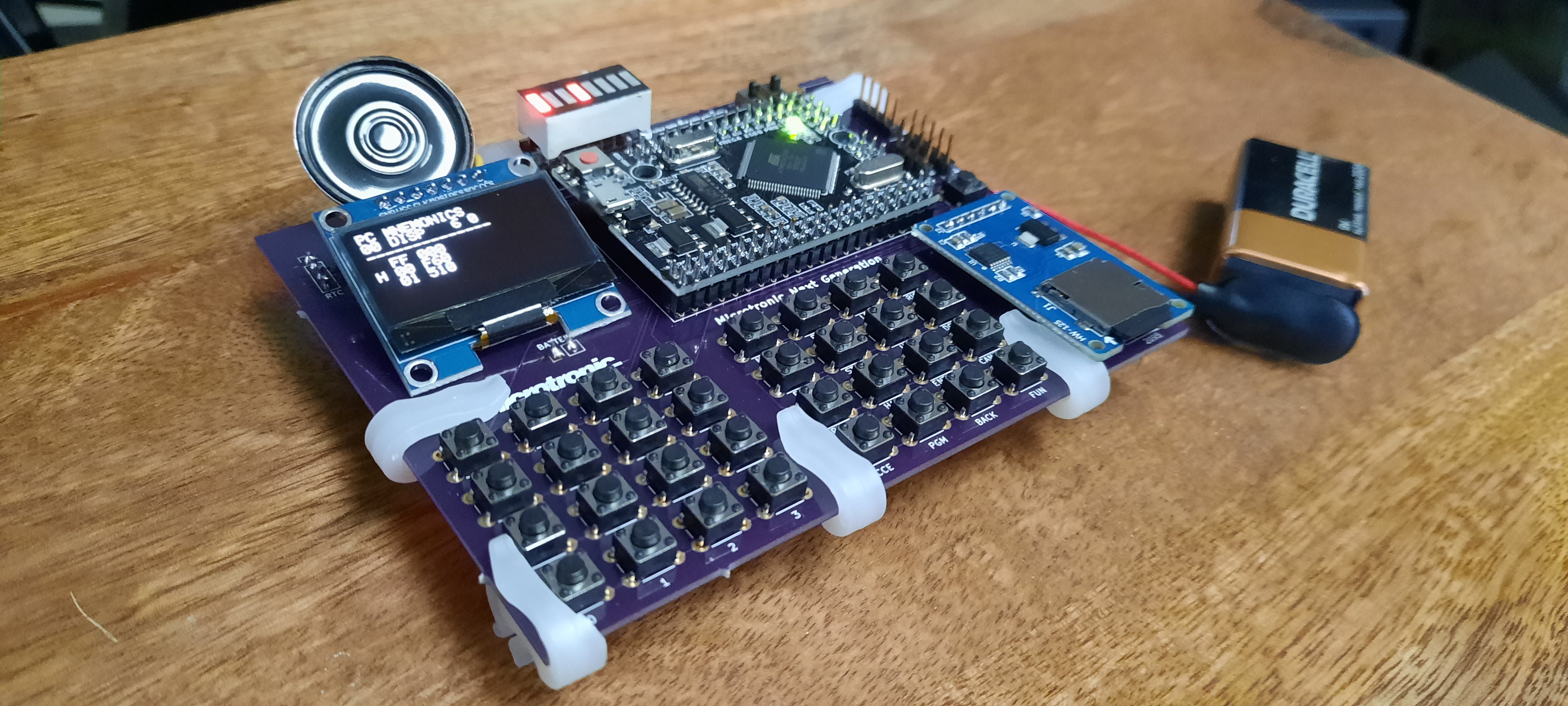
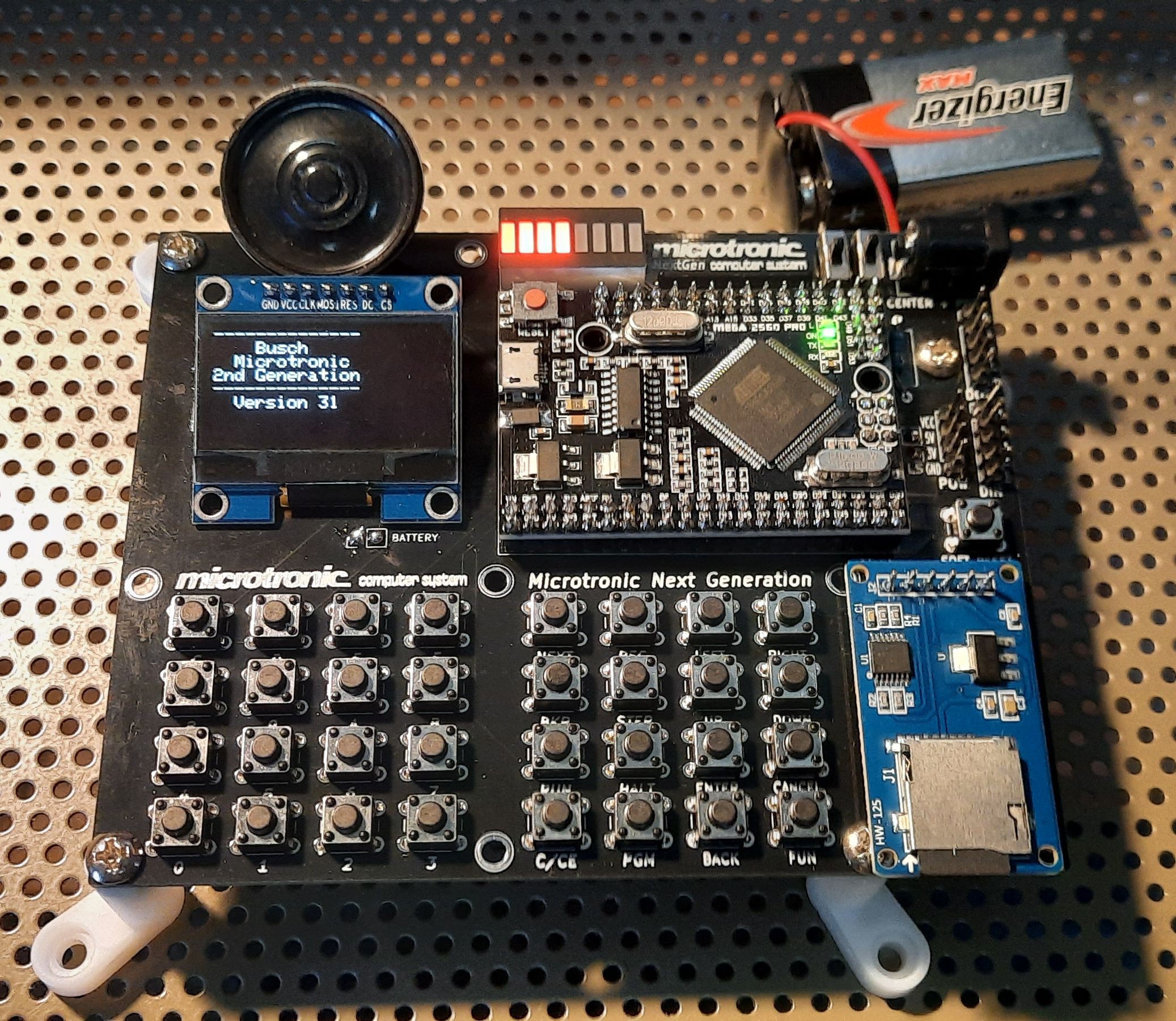
PCB Version 2 for the SH1106 SPI OLED Display:

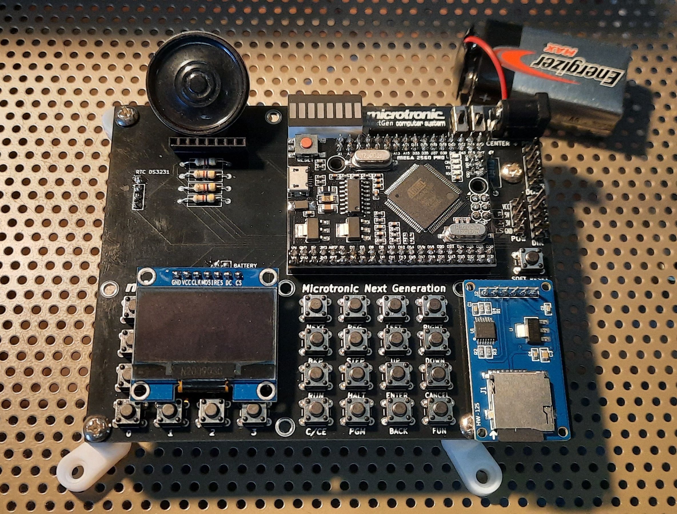
* Really* Final PCB Version 2 for the SH1106 SPI OLED Display with Pulldown Resistors & Proper Feet:
So, what has changed over the 2016 version? In a nutshell:
- Nokia 5110 LCD or SH1106 SPI OLED instead of the 7segment LED + Hitachi HD44780 display: the 7segment LED display was nice since it offered a very 1981-like authentic retro user experience. However, a multi-line LCD offering different screen modes that can display mnemonics, multiple addresses of the machine code program at once, etc., has big advantages. Especially for an educational system. A number of display modes are possible: a simple classic one-line Microtronic display, also in double size font; a mode that displays the memory contents (and optionally mnemonics) at the current Program Counter (PC) and its neighborhood locations; a mode that displays the contents of the work and extra-register sets, and so on.
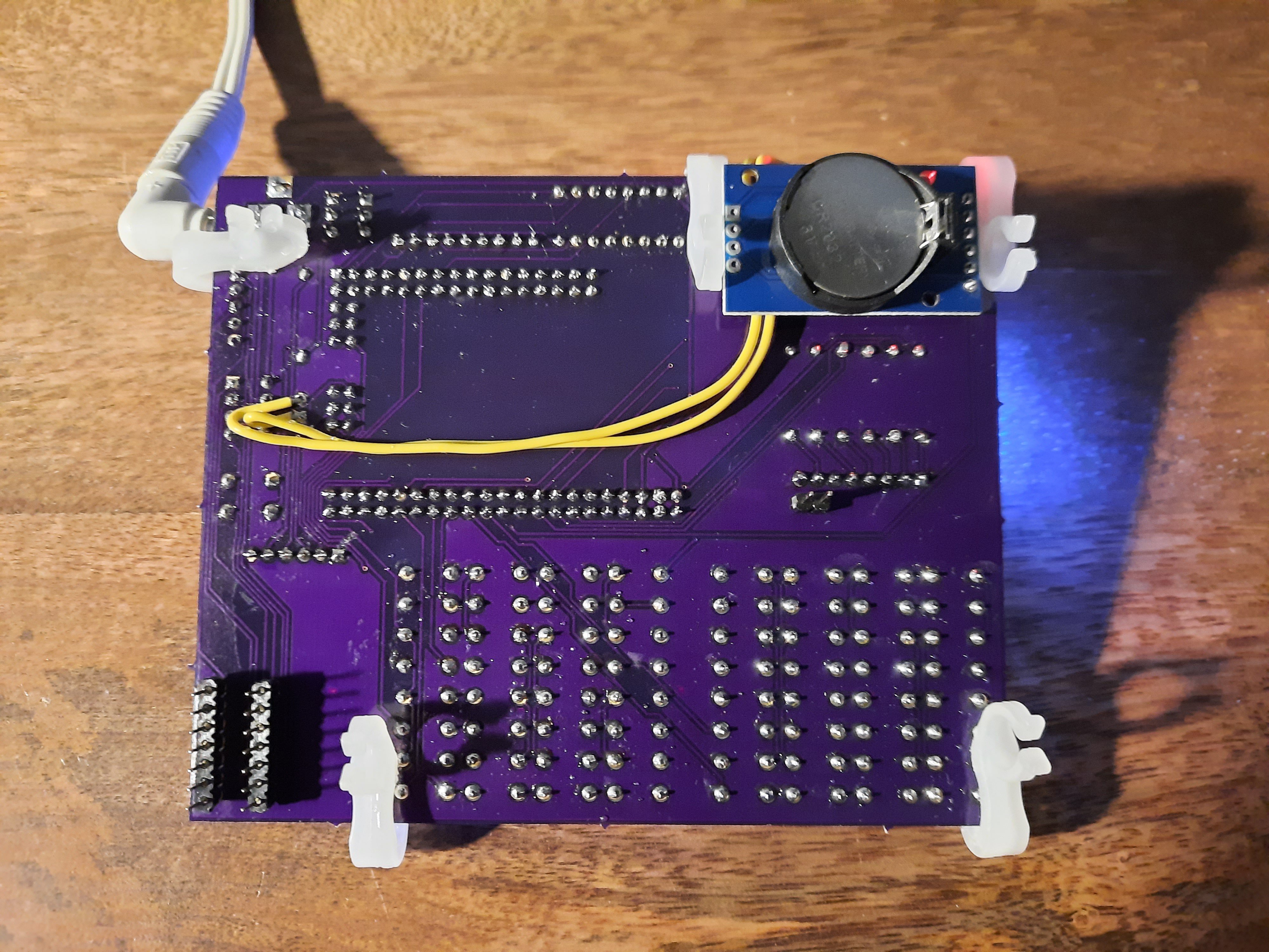
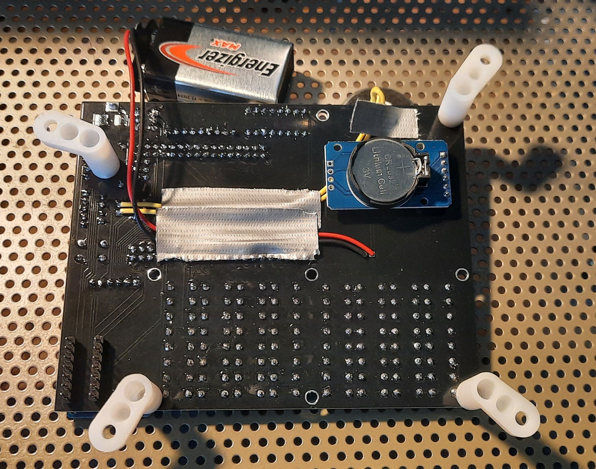
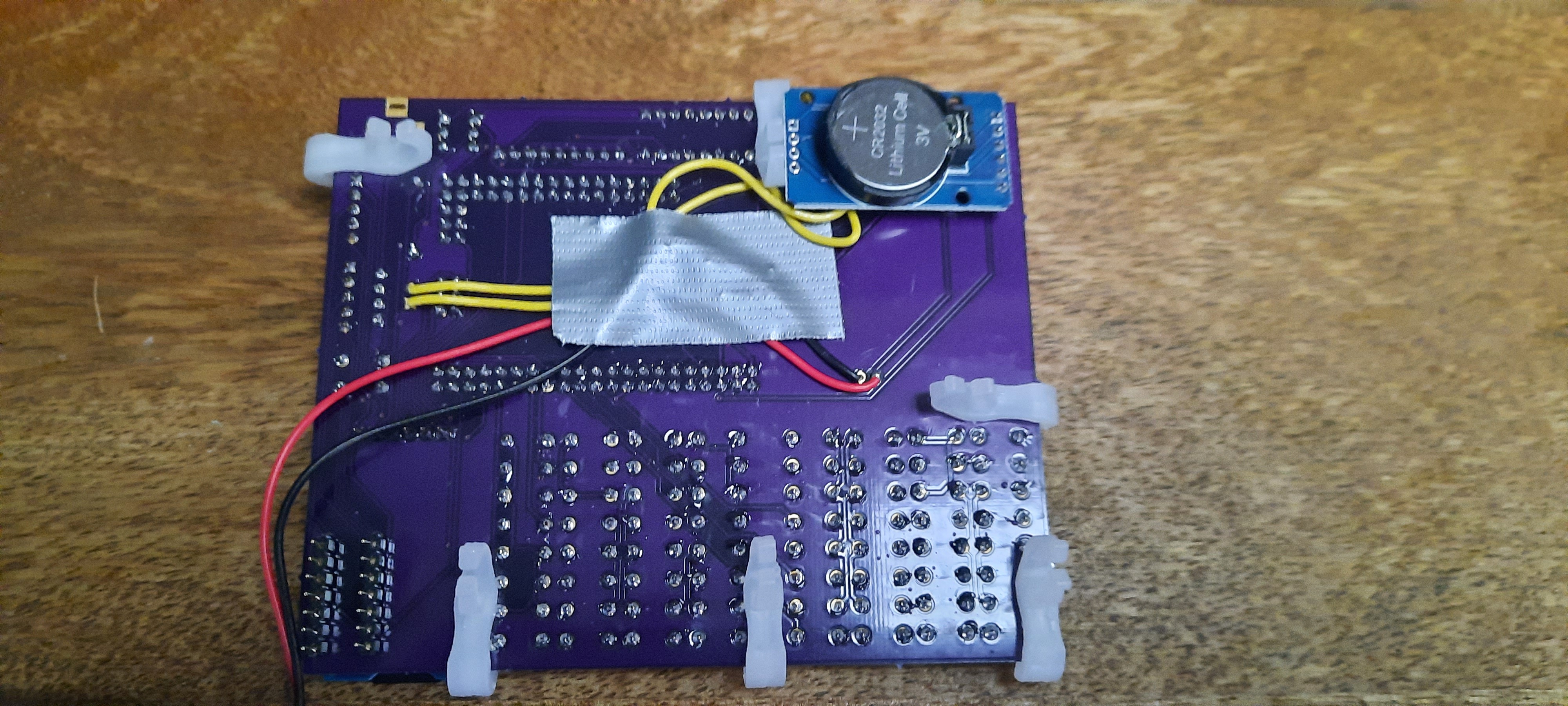
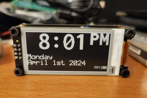
- Real Time Clock: the Microtronic has time / clock functions built in (but no date / calendar). The ROM-program PGM 3 displays the current time, and the ROM-program PGM 4 is used to set the clock. The clock could also be read with a "Get Time" machine code instructions into the registers A to F, so alarm clocks etc. could be implemented. The original Microtronic clock was not battery backed-up though. I have fixed that by linking the PGM 3 and PGM 4 clock functions to a standard DS3231 battery backed-up RTC module. In addition, I have assigned a "set date" function to the built-in ROM program PGM 0. Program PGM 0 usually runs a self-test program, which is not needed here, so it made way for the display / set date function.
- Sound Output: in order to make a sound with the original Microtronic, one usually had to connect a transistor multi-vibrator or a Piezo buzzer to the digital outputs (in the former case, over a simple DA / resistor ladder). However, we figured it would be convenient to have a real SOUND op-code built in. Unfortunately, there are not unused op-codes available in the Microtronic that could be used to this end - every op-code from 000 to FFF is taken and already has a meaning. Fortunately, some of these op-codes are really non-sensensical and hence don't occur in actual existing Microtronic programs. These are the op-codes...


 I also made another video:

 sjm4306
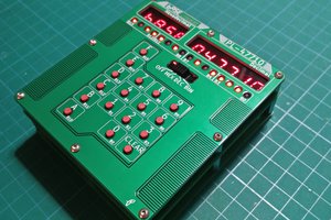
 leumasyerrp
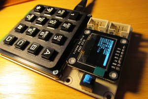
 jaromir.sukuba
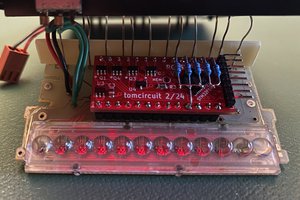
 tomcircuit
That's a really cool recreation. I almost wish I had faux nostalgia for what was never in my past. I had only the KIM-1.