Close
0%
0%

Microtronic - The Next Generation

A Practical 4-Bit Educational Computer
* Reinvented Retro Contest 2021 Winner *

Similar projects worth following
A re-implementation & extension of a classic 4-bit education system from 1981 - the Busch 2090 Microtronic Computer System. This Next Generation Microtronic offers SDcard-based file storage, extended programming and debugging facilities utilizing its large LCD, a battery backed-up real time clock, built-in sound capabilities, and far greater (but adjustable) computing speed. It also acts as a 2095 cassette interface emulator for the classic 1981 Microtronic computer by plugging into its expansion port. The Microtronic has a very comfortable, versatile and intuitive instruction set. The (German) instruction manuals are exceptionally well written. This unique combination makes the system stand out from its 4-bit competition as an education system, even nowadays. It is still highly effective in teaching students the basics of microcomputer (machine code) programming and IMHO, there is no better 4-bit trainer available.

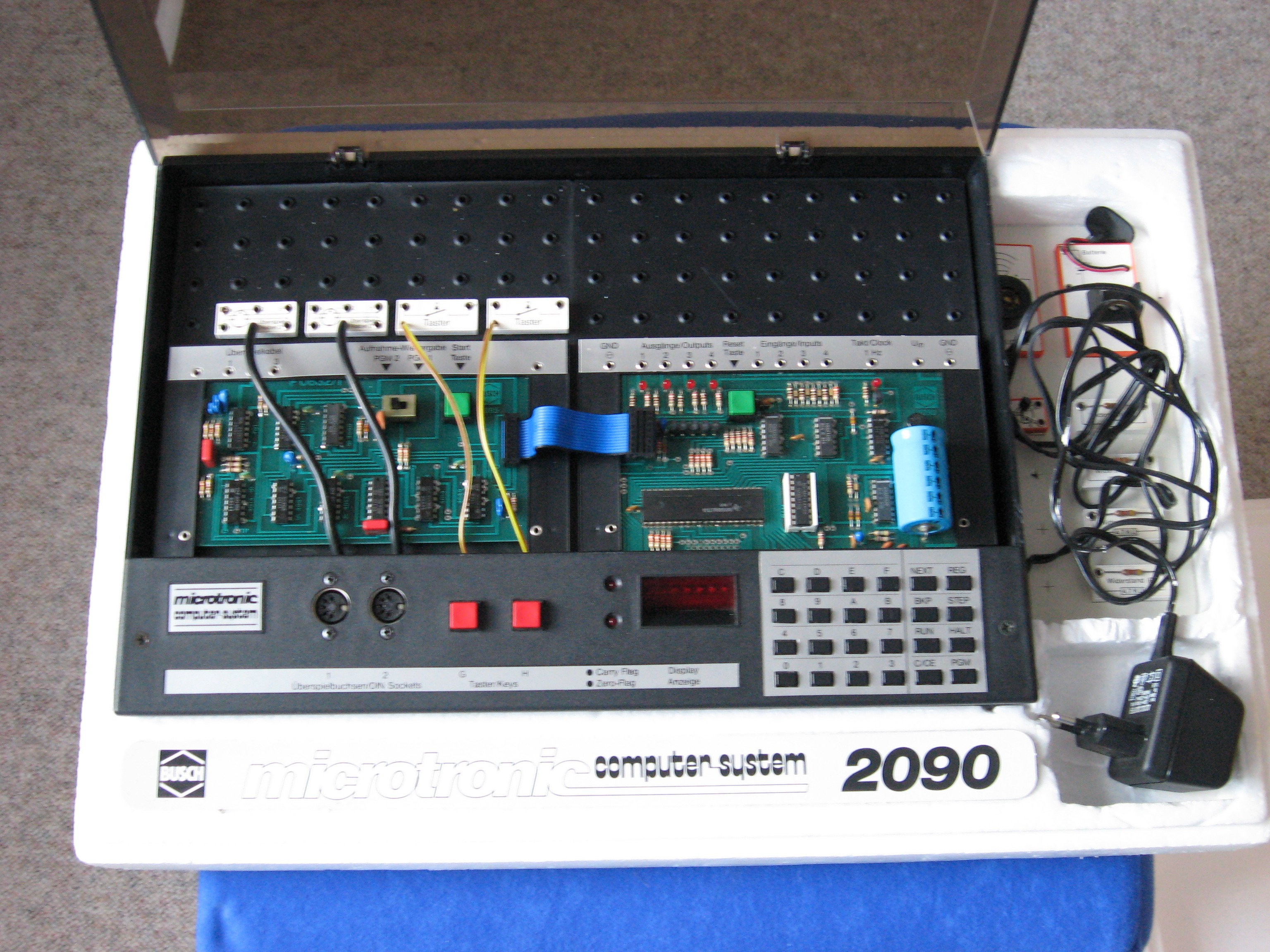
The Busch 2090 Microtronic Computer System was released in 1981 in (West) Germany. It was my first computer on which I learned the basics of (machine language) programming and computer interfacing. This is the original: 
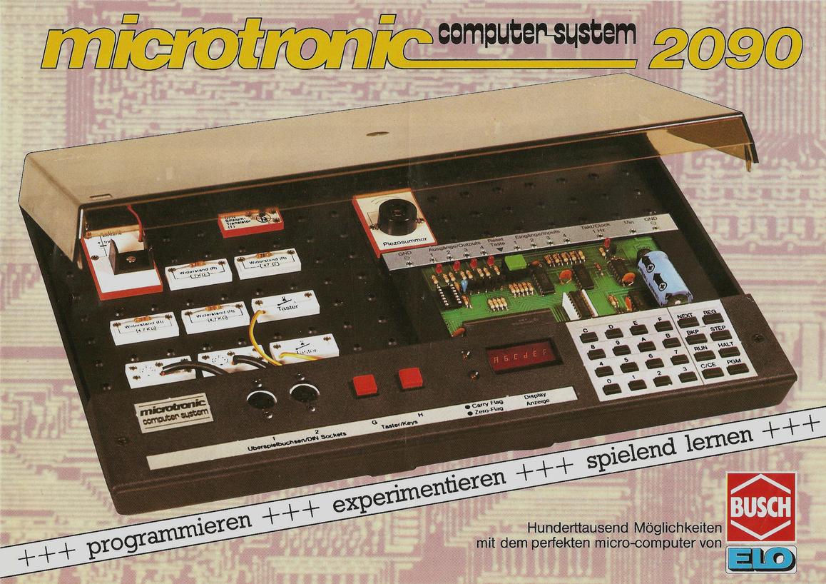

The following picture shows my Microtronic. It was extended with the very rare 2095 Cassette Interface Module (on the left) to allow for cassette tape storage:
In 2016, I had created a talking Arduino-based emulator of the Microtronic system:
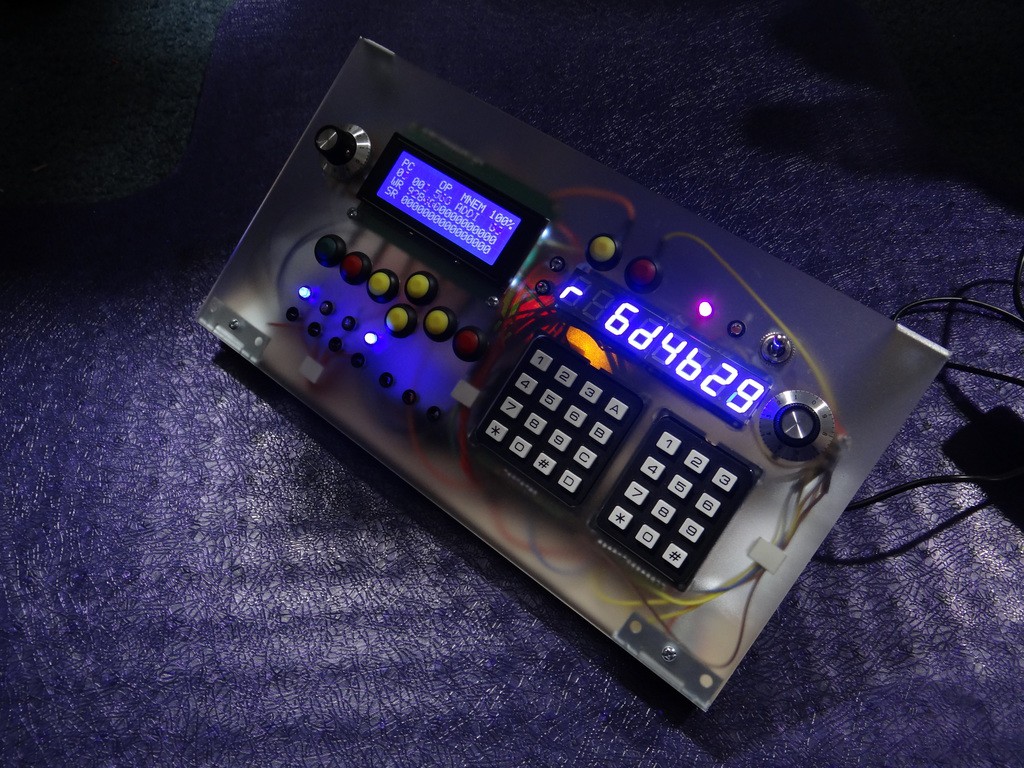

This predecessor project - The Talking Microtronic Emulator - also has a page here on Hackaday. Background info about the Microtronic (i.e., details about its virtual CPU and its instruction set) are provided as well: 

https://hackaday.io/project/11560-the-talking-microtronic-computer-system-emulator

Even though the Microtronic uses a TMS 1600 CPU, it was actually not programmed in TMS machine language. Rather, the (mask-programmed) TMS 1600 was running a monitor program that emulated a much more versatile, powerful, and flexible CPU architecture much more suitable for an education system. It even included high-level instructions / op-codes for multiplication, division, time / clock functions, random numbers, display, digital input & output, keyboard input, etc. A very nice instruction set.


Back to 2020: The Next Generation Microtronic project (these pages) is the continuation, culmination and wrap up of this work. This time, I have a proper PCB with greater reliability and durability than my previous breadboard big-mess-of-wires prototypes, hence preserving my efforts for the future. 

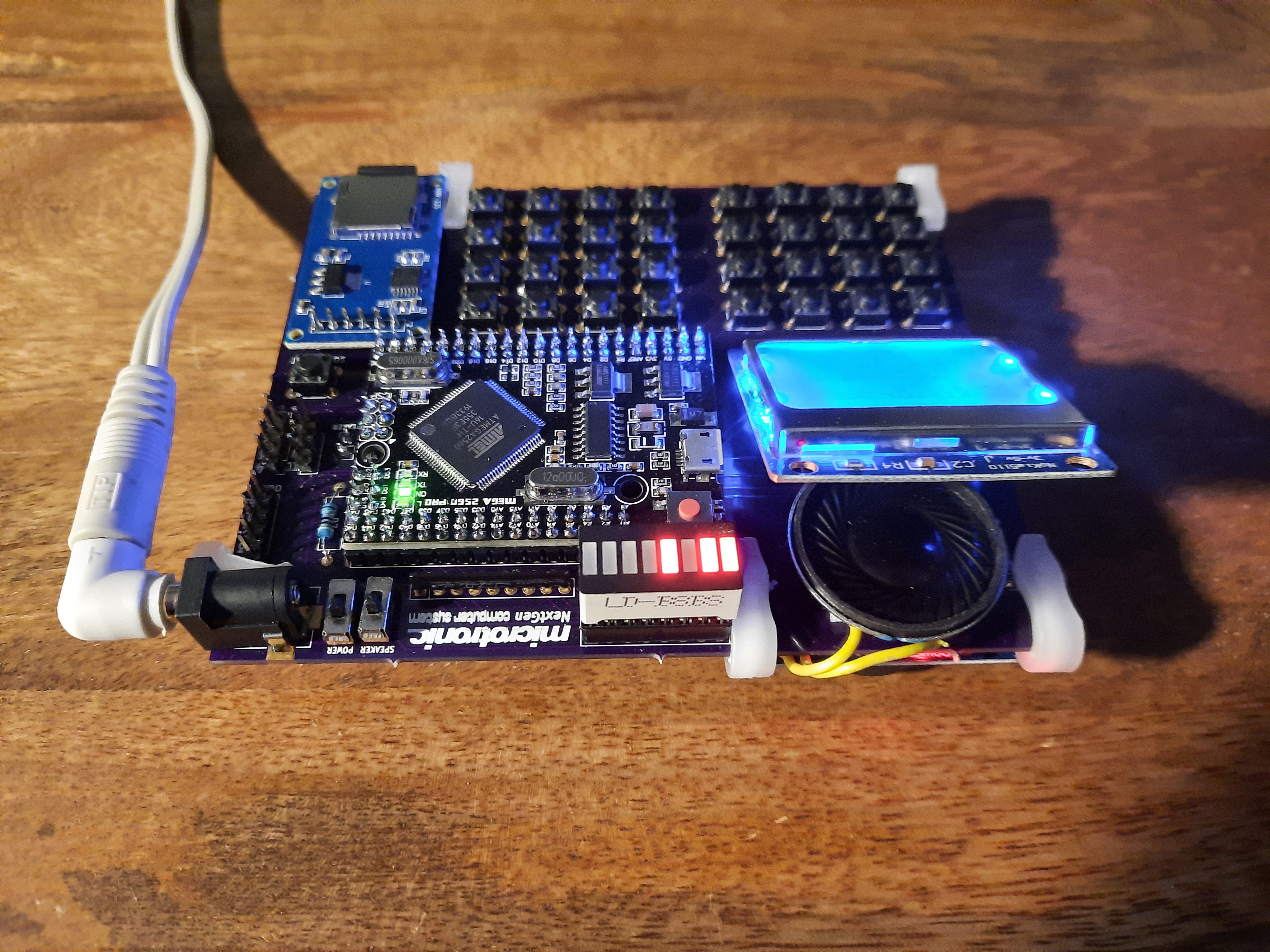
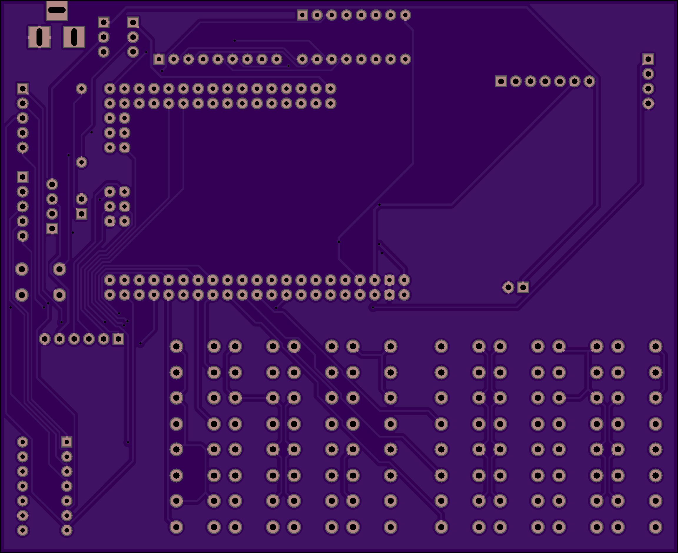
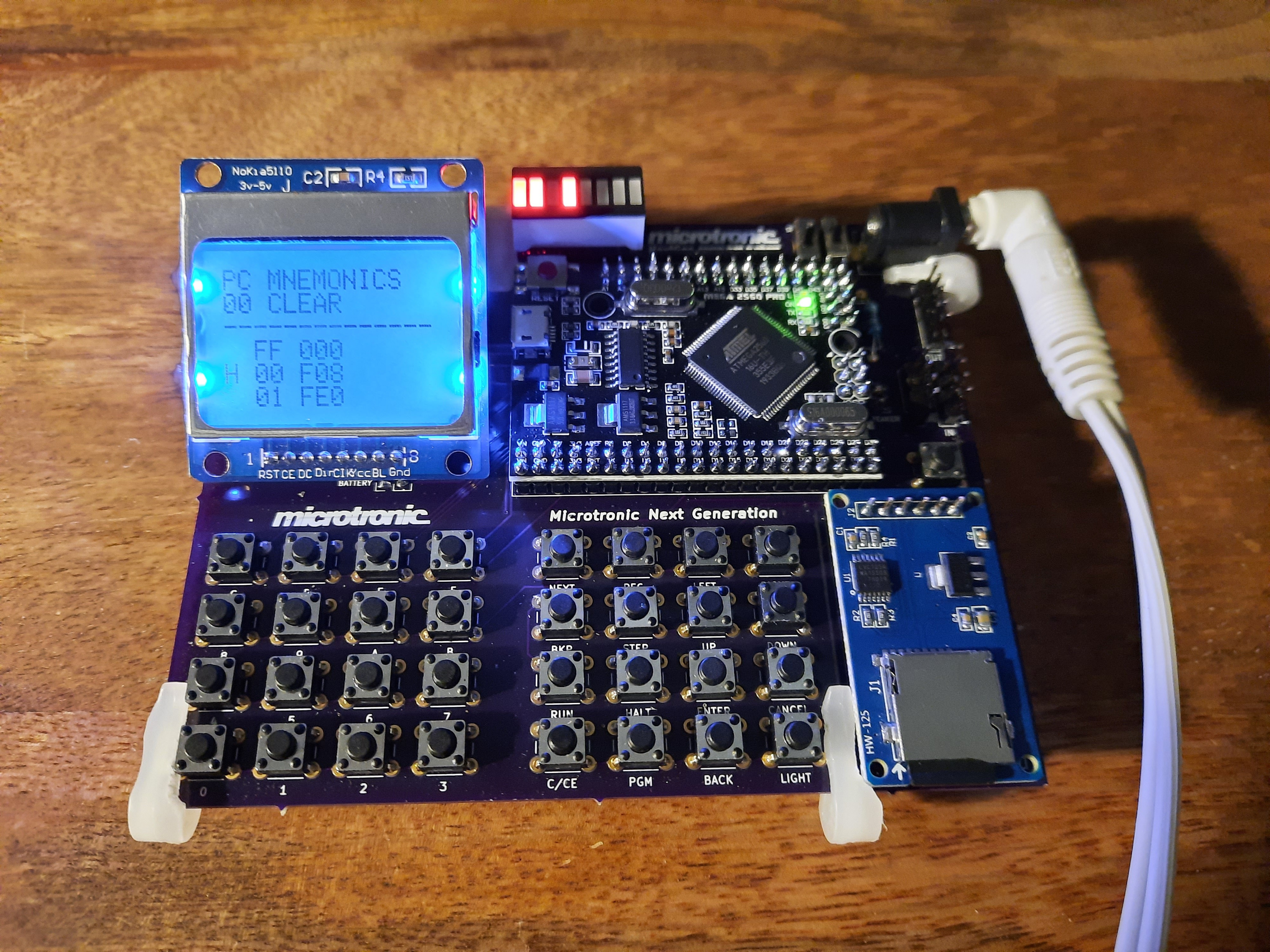
PCB Version 1 for the Nokia 5110:
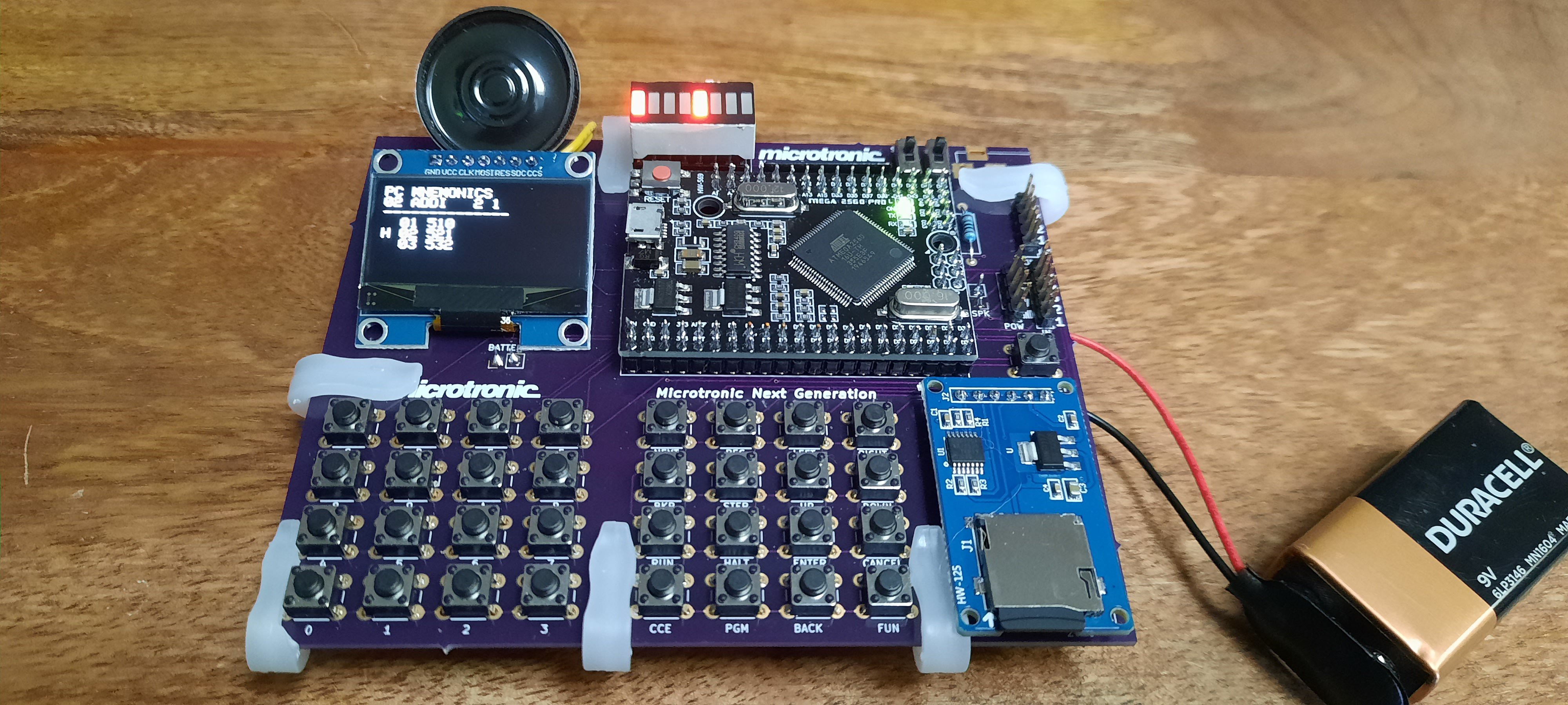
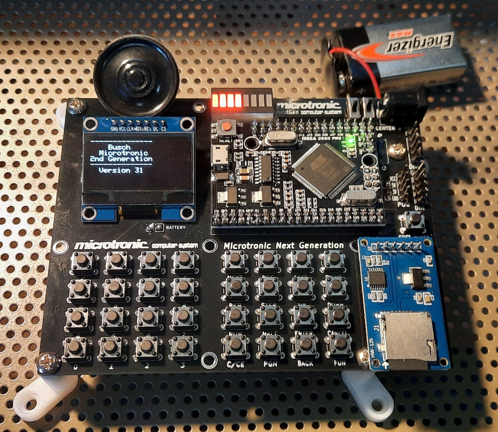
PCB Version 2 for the SH1106 SPI OLED Display: 
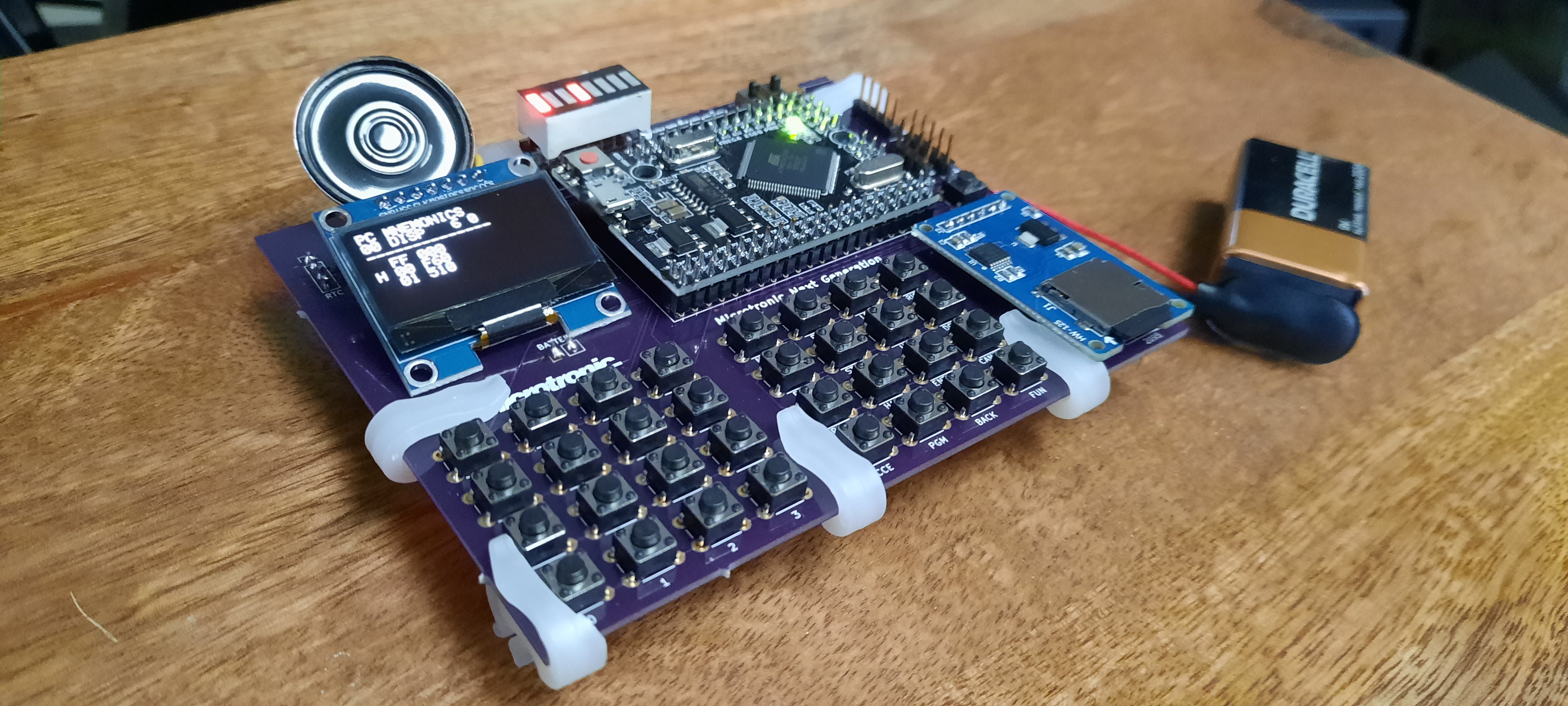
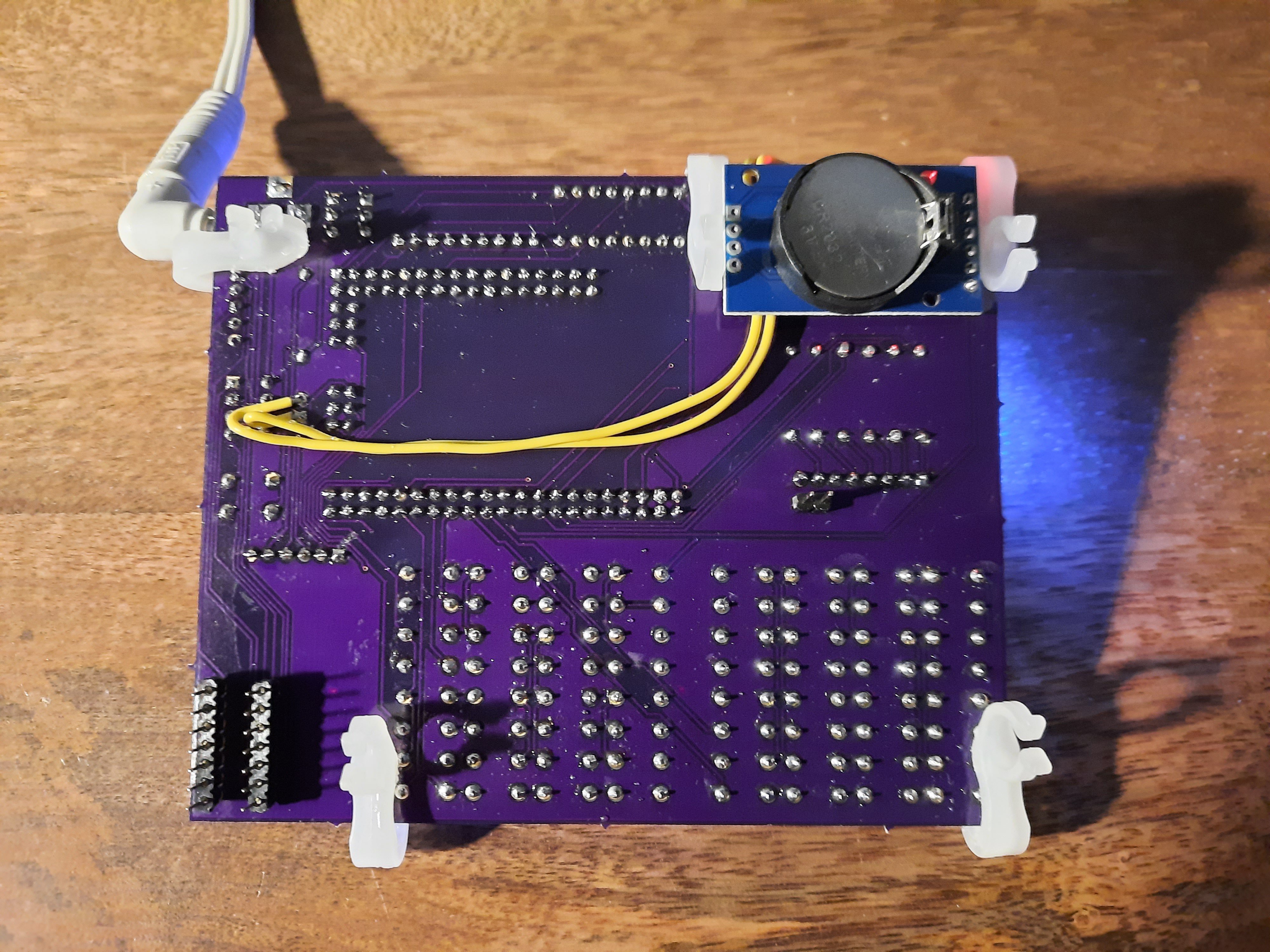
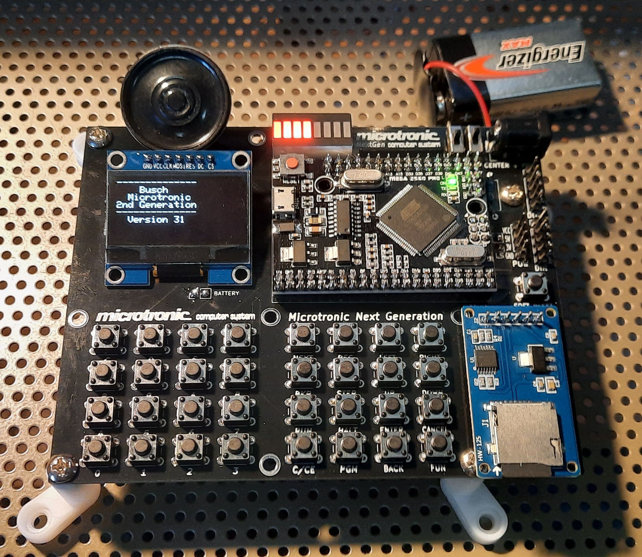
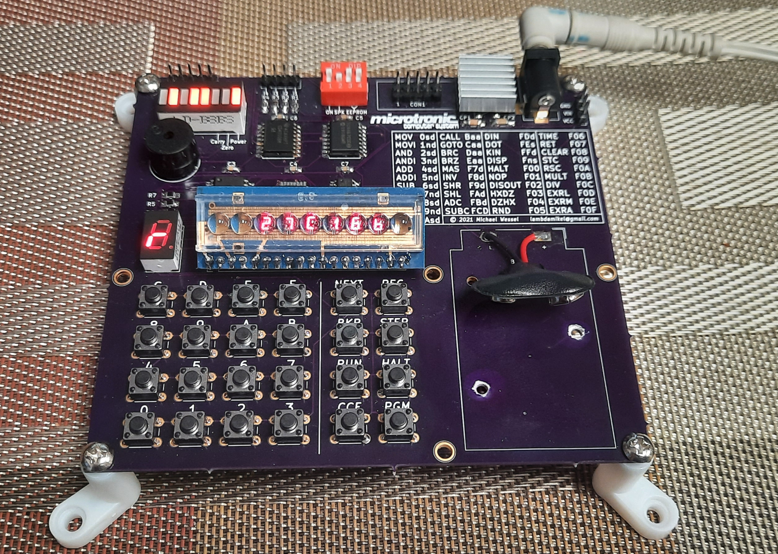
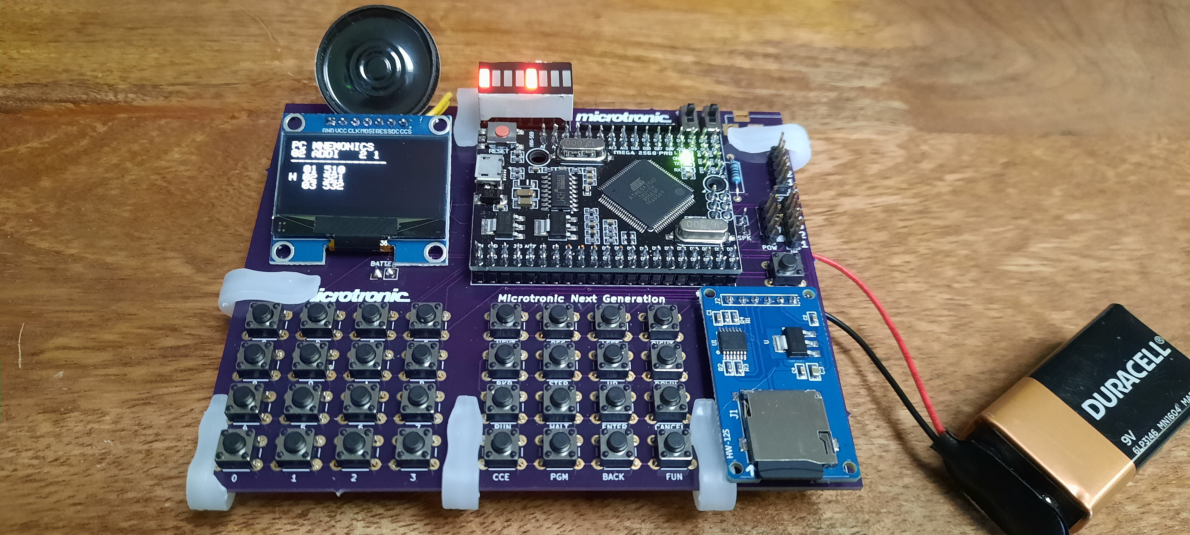
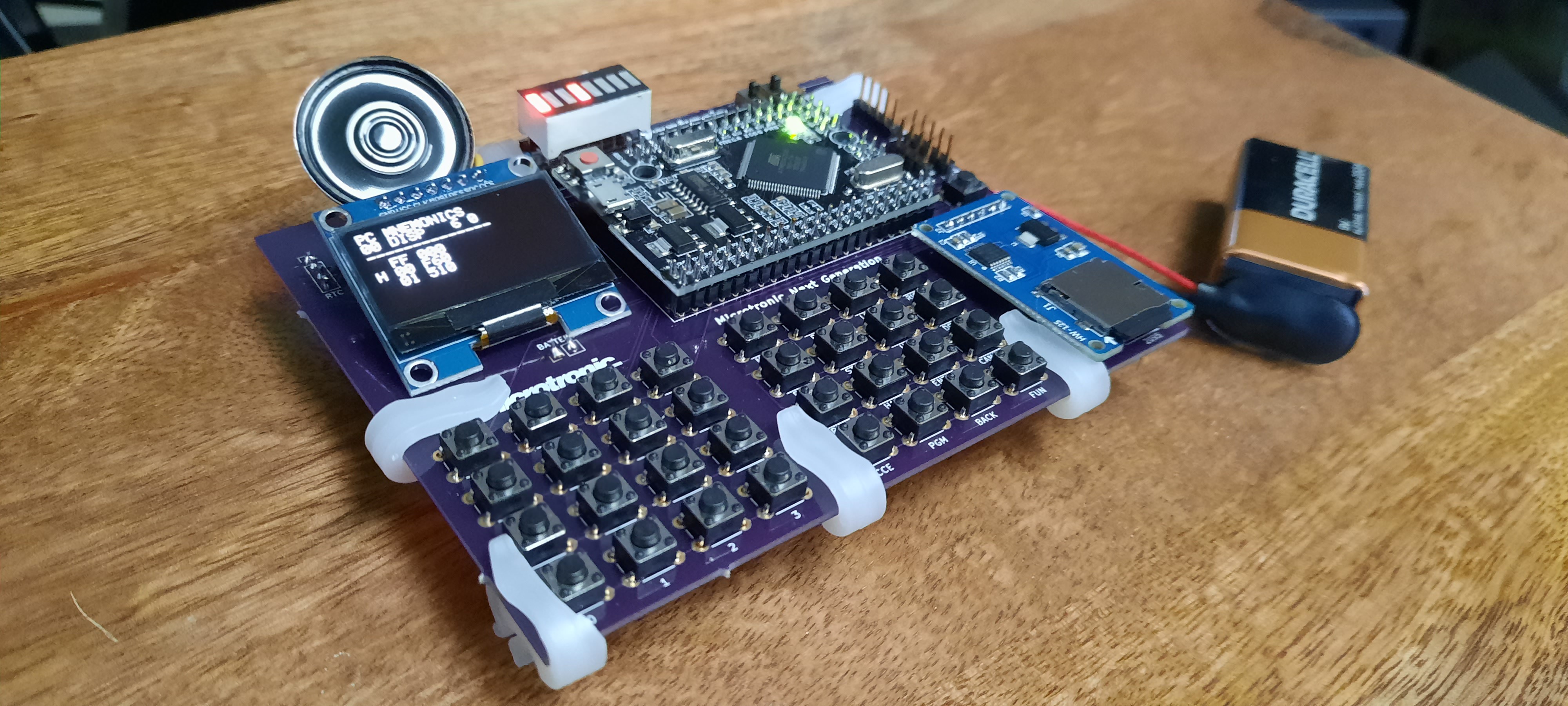
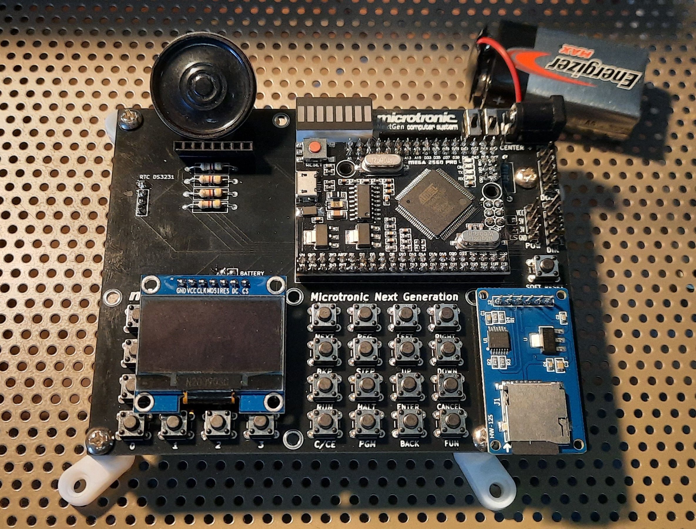
* Really* Final PCB Version 2 for the SH1106 SPI OLED Display with Pulldown Resistors & Proper Feet: 

So, what has changed over the 2016 version? In a nutshell:

  • Nokia 5110 LCD or SH1106 SPI OLED instead of the 7segment LED + Hitachi HD44780 display: the 7segment LED display was nice since it offered a very 1981-like authentic retro user experience. However, a multi-line LCD offering different screen modes that can display mnemonics, multiple addresses of the machine code program at once, etc., has big advantages. Especially for an educational system. A number of display modes are possible: a simple classic one-line Microtronic display, also in double size font; a mode that displays the memory contents (and optionally mnemonics) at the current Program Counter (PC) and its neighborhood locations; a mode that displays the contents of the work and extra-register sets, and so on. 
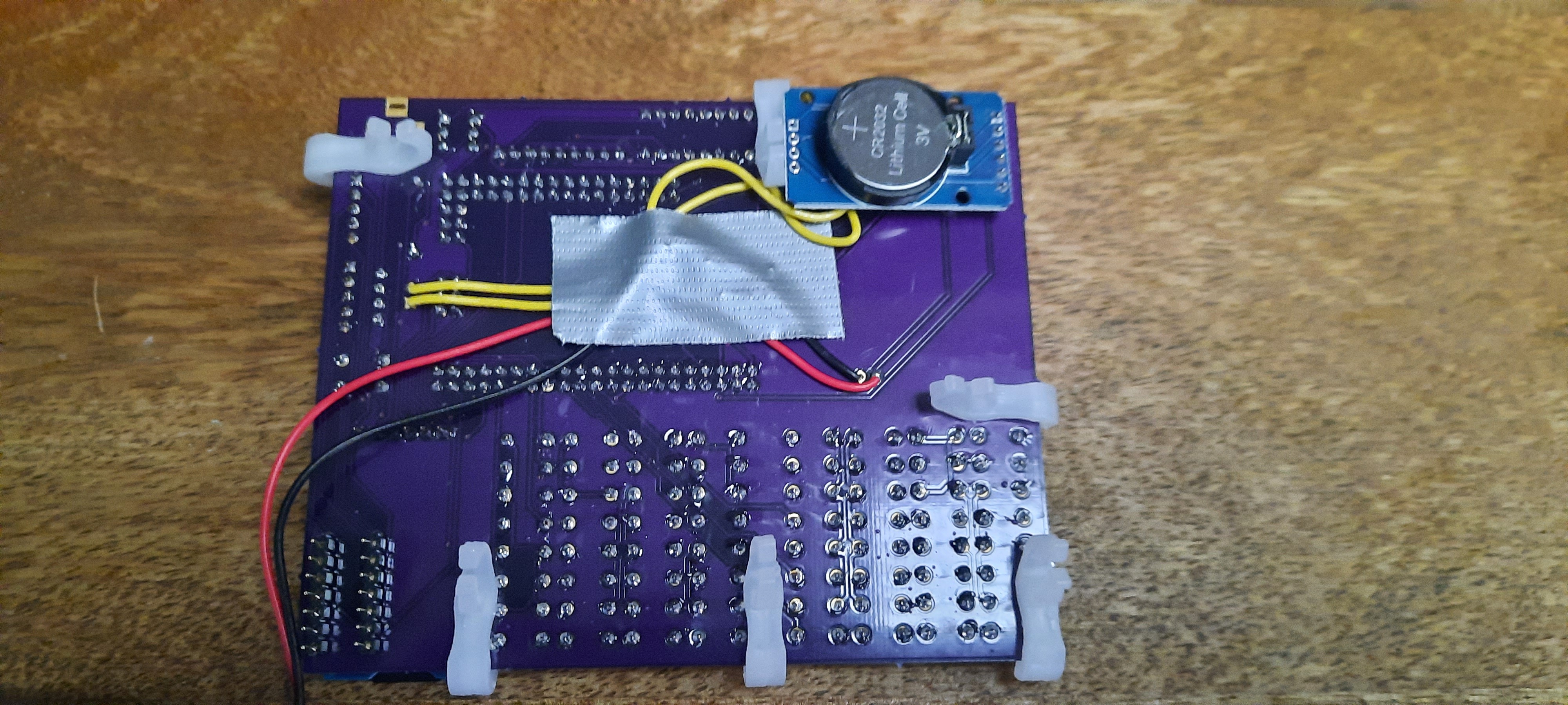
  • Real Time Clock: the Microtronic has time / clock functions built in (but no date / calendar). The ROM-program PGM 3 displays the current time, and the ROM-program PGM 4 is used to set the  clock. The clock could also be read with a "Get Time" machine code instructions into the registers A to F, so alarm clocks etc. could be implemented. The original Microtronic clock was not battery backed-up though. I have fixed that by linking the PGM 3 and PGM 4 clock functions to a standard DS3231 battery backed-up RTC module. In addition, I have assigned a "set date" function to the built-in ROM program PGM 0. Program PGM 0 usually runs a self-test program, which is not needed here, so it made way for the display / set date function.
  • Sound Output: in order to make a sound with the original Microtronic, one usually had to connect a transistor multi-vibrator or a Piezo buzzer to the digital outputs (in the former case, over a simple DA / resistor ladder). However, we figured it would be convenient to have a real SOUND op-code built in. Unfortunately, there are not unused op-codes available in the Microtronic that could be used to this end - every op-code from 000 to FFF is taken and already has a meaning. Fortunately, some of these op-codes are really non-sensensical and hence don't occur in actual existing Microtronic programs. These are the op-codes...
Read more »

schematics.jpg

Schematics

JPEG Image - 201.27 kB - 12/22/2020 at 04:53

Preview

View all 10 components

  • We are winners of the Reinvented Retro Contest - THANK YOU!

    Michael Wessel07/18/2021 at 13:45 0 comments

    What a nice surprise! We are among the lucky winners of the REINVENTED RETRO CONTEST - what an honor to be selected from the pool of 138 amazing contenders!

    https://hackaday.com/2021/07/17/reinvented-retro-contest-winners-announced/

    Thanks  so much to the Hackaday organizers, judges and community for the votes!!

    Whereas I started a first version of this project in 2016, this project would not have reached its current level of maturity and form factor without the "Microtronic Second Generation" Sister Project and my team members Frank de Jaeger, Manfred Henf, and Lilly. So I am gratefully accepting the prize for this extended team.

    It was Frank who made me resurrect the project in 2020, suggested to use the Nokia 5110 display, and shrink down the form factor by switching from the Arduino Mega 2560 R3 used in my 2016 version to the Mega MiniPro 2560 board, resulting in a much more compact setup. Manfred did the 3d design and printing of the Second Generation case parts that nicely integrates into an original Busch console, and Lilly did a great job in quality control (testing, bug finding, ...) and significantly contributed to the firmware of yet another Microtronic sister project, the Retro-Authentic Bubble LED version: 

    https://hackaday.io/project/180252-a-retro-authentic-microtronic-emulator

    More info about the "Microtronic Second Generation" sister project (which was mainly driven by Frank and Manfred), and the "Retro-Authentic Bubble LED Display Microtronic" sister project below. THANKS TO ALL OF YOU!

    https://www.rigert.com/ee-forum/viewtopic.php?t=2497

    https://hackaday.io/project/180252-a-retro-authentic-microtronic-emulator

  • A Microtronic Emulator with LED Bubble Display

    Michael Wessel06/09/2021 at 19:05 0 comments

    Here is a new take on this project - more retro-authentic than ever! Who needs displays if one can have a 6digit 7segment LED bubble display, like its 1981??
    https://hackaday.io/project/180252-a-retro-authentic-microtronic-emulator

  • Final Next Generation PCB Version - Pulldowns & Feet!

    Michael Wessel01/21/2021 at 17:15 0 comments

    I added pulldown resistors to the digitial inputs to have higher electrical compatibility with the original Microtronic; i.e., electronics experiments as decribed in the Busch manual require non-inverted logic (I was using the internal pullups previously). Ideally, I should have added transistor drivers or at least 2 74LS243 4bit bus transceivers (one for input DIN, one for output DOT). Anyhow, the experiments from the manuals I tried so far all worked; none of them sources or sinks a lot of current into the GPIOs.

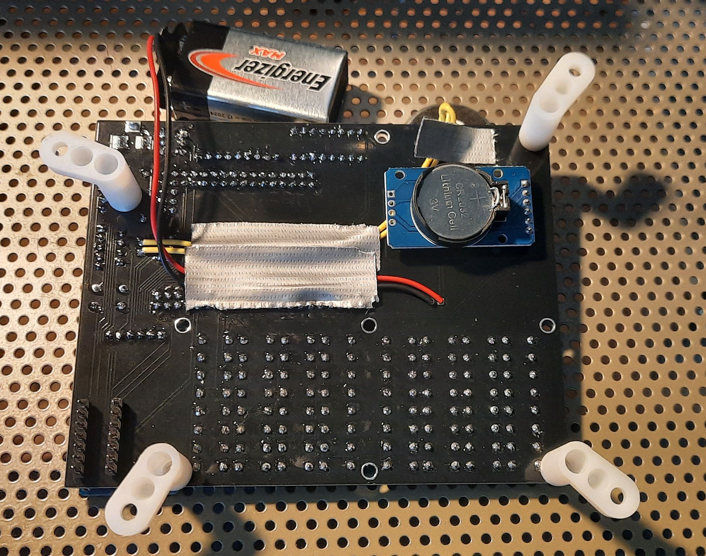
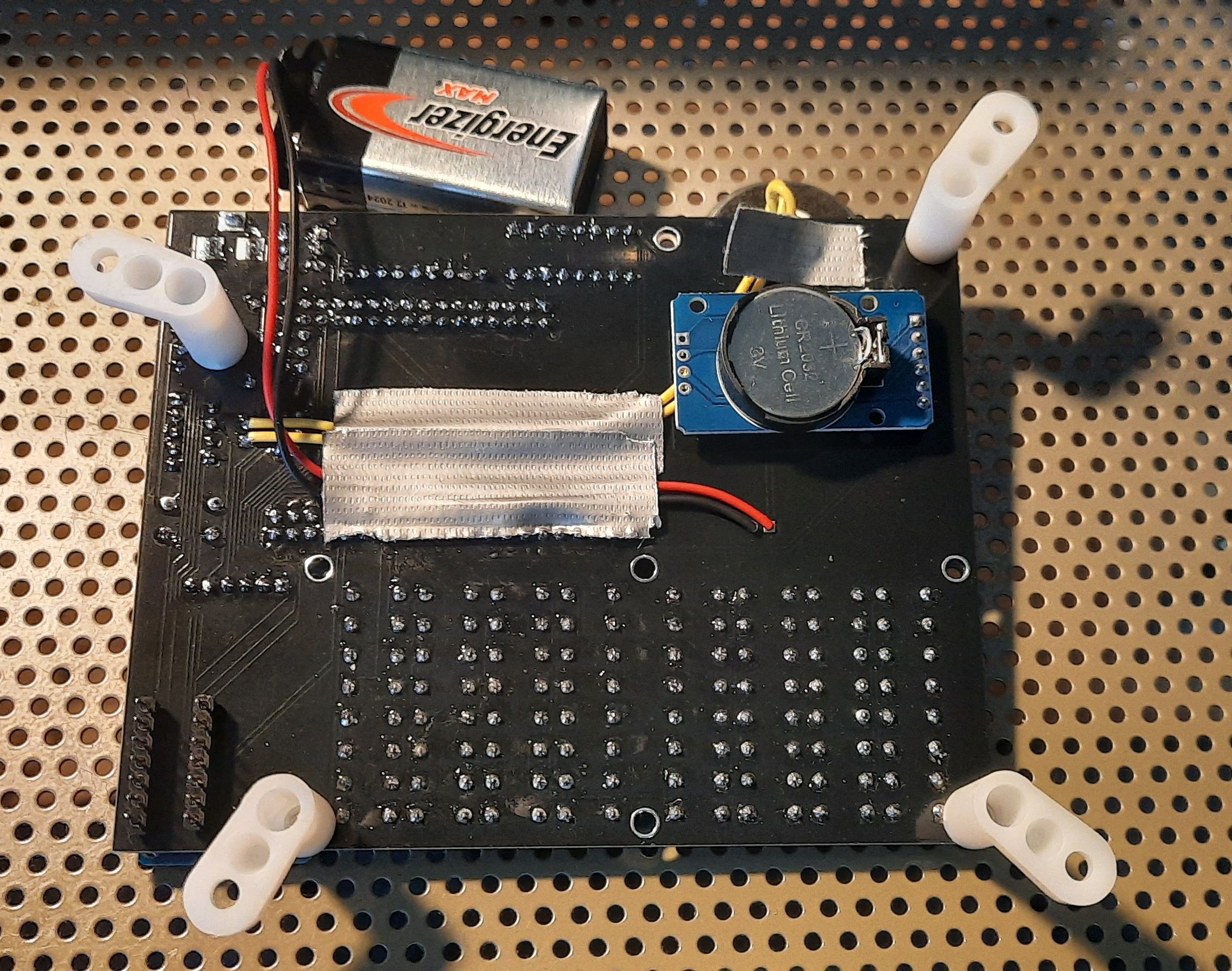
    Also, mirror holders from ACE Hardware make a great set of PCB feet! The PCB is final now - OK, a battery holder would be nice... anyhow, there is always something that needs improvement with these projects, and sometimes, good enough must be good enough ;-) I consider the project done by now.

  • Firmware Bugfix (Inverted Output Ports) & Busch Electronics Kits Experiments

    Michael Wessel01/04/2021 at 06:21 0 comments

    Trying an official experiment from the Microtronic manual to check compatibility of the output ports with Busch electronics experiments / circuits as described in the Microtronic manual. I had the output ports inverted previously - with that being fixed in the firmware, the experiment conducted here demonstrates principles of "data transmission". The Microtronic Next Generation is driving a CLOCK and a RESET line into a Busch 2075 Counter Module, and a (decimal) digit is being transmitted from the Next Generation to the Counter Module. With the corrected firmware (non-inverted outputs) it works fine.

  • Second PCB Version for SH1106 SPI OLED & Running from Battery

    Michael Wessel12/29/2020 at 17:51 0 comments

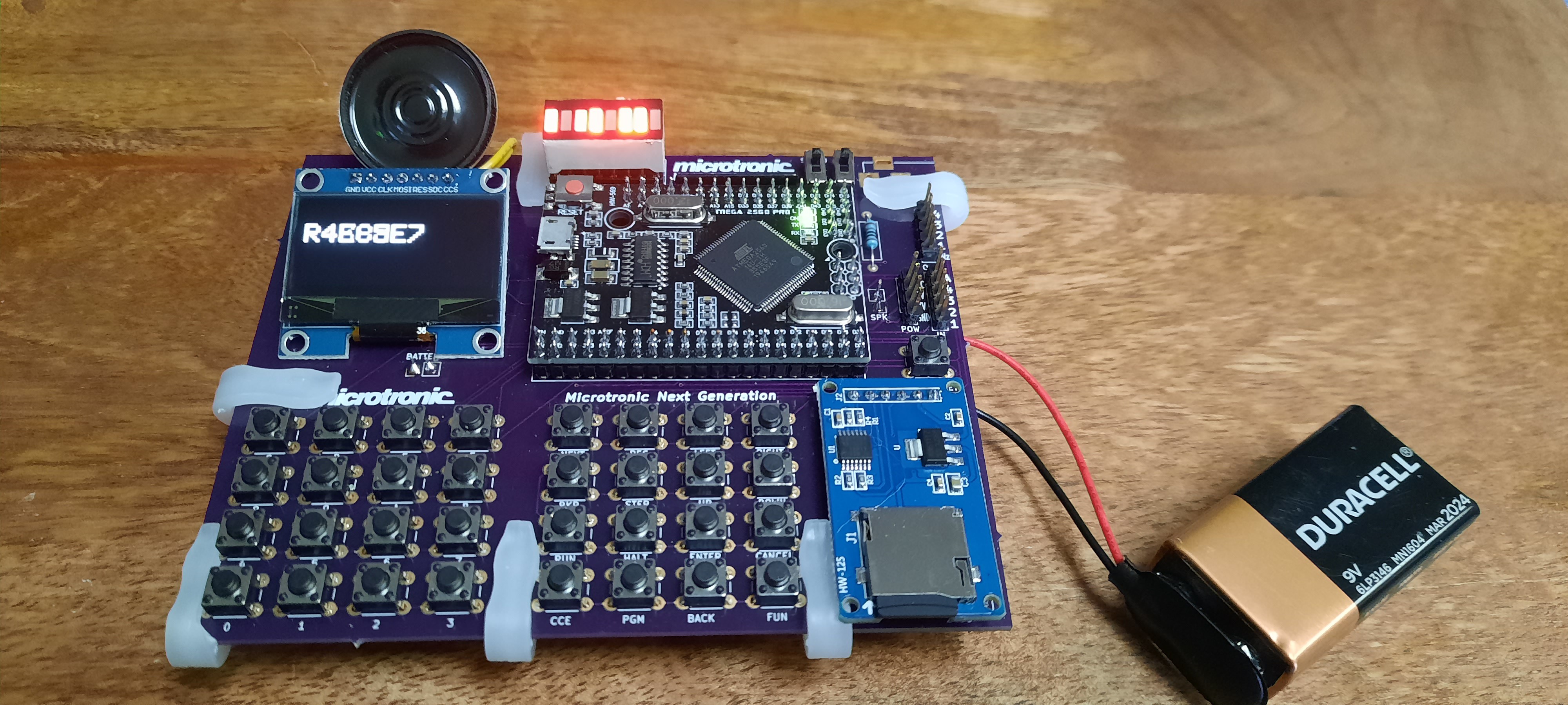
    The OshPark PCBs work flawlessly! Functionality is identical to the Nokia 5110 version. Note that I am running from battery this time!

    I also made another video: 

  • Second batch of PCBs accomodating the SH-1106 SPI OLED display are on the way

    Michael Wessel12/23/2020 at 16:42 0 comments

    Just got note from OshPark that my 2nd PCB batch is on the way: I swapped the Nokia 5110 with an SH-1106 SPI OLED display. The SH-1106 SPI was selected after a number of experiments that I conducted in order to identify the fastest monochrome display for the project. The Nokia is nice, but a little bit too laggy; it gets too blurry if refreshed fastly. The SPI SH-1106 doesn't have that issue and is crystal sharp as well as a bit faster than the Nokia:

View all 6 project logs

Enjoy this project?

Share

Discussions

Ken Yap wrote 06/10/2021 at 22:44 point

That's a really cool recreation. I almost wish I had faux nostalgia for what was never in my past. I had only the KIM-1.

  Are you sure? yes | no

Michael Wessel wrote 06/10/2021 at 23:01 point

Thanks Ken - since we are both into LEDs (just checked your projects and left you a like for the binary clock - neat!), maybe you also like my follow-up to this one: 

https://hackaday.io/project/180252-a-retro-authentic-microtronic-emulator

  Are you sure? yes | no

Ken Yap wrote 06/10/2021 at 23:26 point

Thanks, that was the page I originally intended to post the comment to. Very nice.

  Are you sure? yes | no

KryptoKidz wrote 01/20/2021 at 14:14 point

looks cool, is there a way to build a DIY version of that? thanks!

  Are you sure? yes | no

Michael Wessel wrote 05/22/2021 at 03:27 point

Thanks @KryptoKidz I missed your message until now: the Gerbers are online in the Github repo by now: 

https://github.com/lambdamikel/Busch-2090/tree/master/gerbers


And Arduino sketch here:

https://github.com/lambdamikel/Busch-2090/tree/master/microtronic-nextgen-sh1106-spi

  Are you sure? yes | no

Michael Wessel wrote 12/22/2020 at 15:09 point

Thank you! Yes, I was thinking about a FPGA version with video output and a better keyboard as well. Maybe a good 2021 project :-) My "Microtronic colleagues" mentioned in the description (Frank from Belgium and Manfred from Germany) have a better keyboard for the 2nd Generation Microtronic that installs into the Busch console. The telephone matrix keypads that I used for the prototype aren't bad either. Still, lots of ideas and things to improve and try! Regarding 80x25 screen, not so sure if this is needed given that this is only machine code programmable.

Regarding FPGA, you also have to consider the purpose and price of the project... the ATMega 2560 MiniPro literally costs me 3 or 4 USD. No FPGA is that cheap. If I wanted to sell these assembled or as a kit (after providing some translation of the Busch Manuals to English) I could do so for 30 USD on Tindie or so. That's only possible by using inexpensive stock components like the MiniPro. So I am not sure that FPGA adds anything here (other than price and maybe video output, which is not what I really need for this project).

Anyhow, thanks for the input and all the best for 2021!


Cheers Michael

  Are you sure? yes | no

Similar Projects

Does this project spark your interest?

Become a member to follow this project and never miss any updates