Enrico Gueli
-
Added real time clock
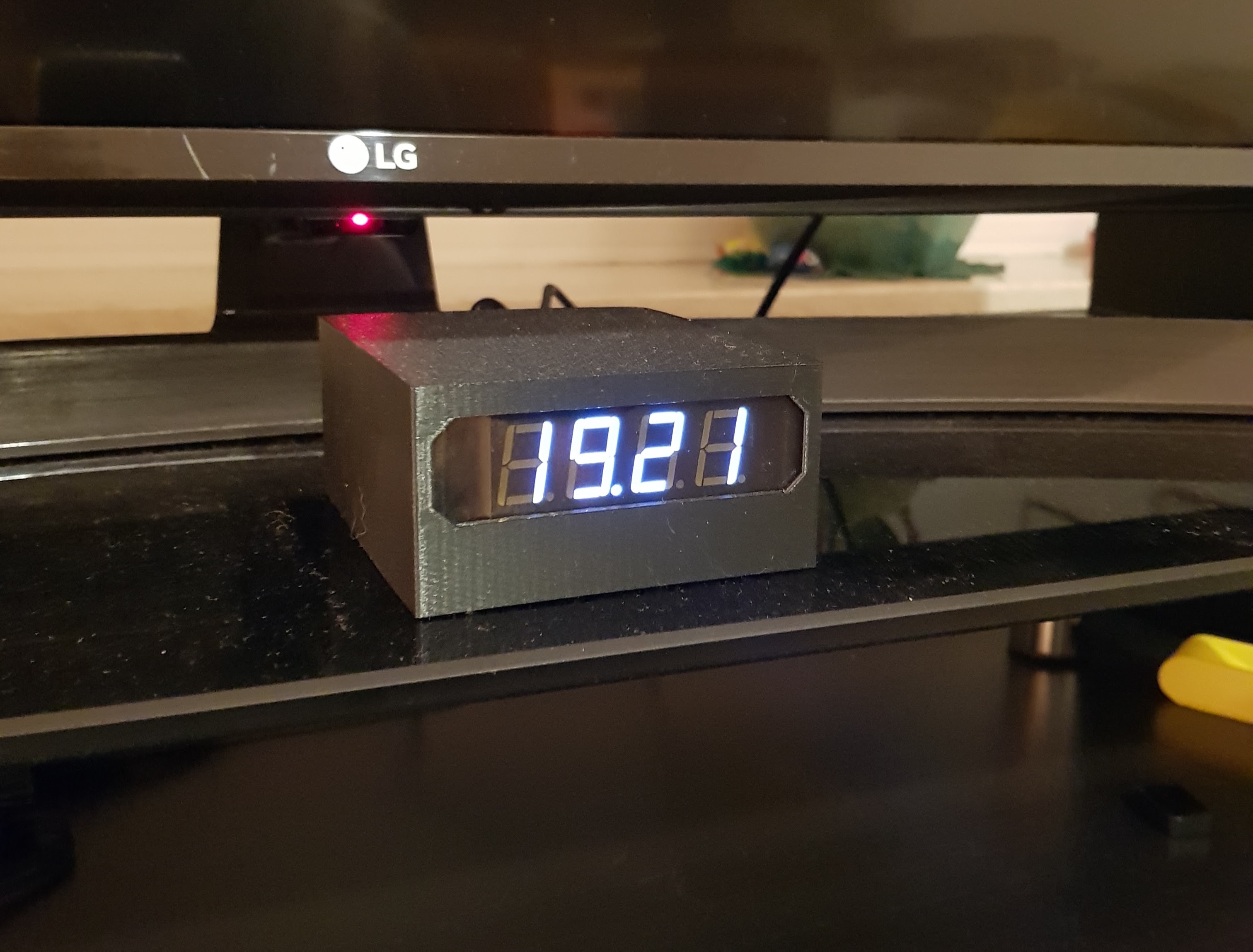
02/10/2021 at 18:23 • 0 commentsSometimes it would be nice to know what time it is while you're watching TV. Like when you're in lunch break while working from home and you have an upcoming meeting.
Since the Speaker has four nice 7-segment displays, and can connect to Internet, why not adding a real time clock?
First I introduced a mechanism for a "background text" to be displayed while no other important messages have to be displayed.
Then I grabbed the TIme library (here's an example using NTP) and hooked it up to the rest of the system. And added a little logic to turn it off and on with a rarely-used button of the remote control.
And there it is:
![]()
-
Poor man's exception handling
02/07/2021 at 11:29 • 0 commentsOnce a IR command is received, SpeakerIR will try to send a command to the speaker. When things go wrong, the display will show error messages like "Ev" or "Et". E means error, and the second letter referred to which action failed: "v" is volume change, "t" is TV input select and so on. But that doesn't tell why exactly did it fail :)
---------- more ----------Knowing that "the volume-change action failed" doesn't tell me much, because I'm the one issuing the action, so that detail is kinda irrelevant. Sure I'd like to know that my action couldn't be performed, but then a generic "error" would be enough.
That was a limitation I wanted to overcome somehow. For example, I'd like to know if the failure is due to lack of connectivity, or if the speaker didn't respond properly. With such information I can quickly fix the problem, e.g. by turning on the speaker if it was powered off.
The limitation was in the software. When an action is performed, a function is called. That usually returns a boolean value, that is true if everything went fine. If one of the called functions fails, it will return false and a notification will be performed:
void onVolumeUp() {
  if (!increaseVolume(speaker)) {
    notifyVolumeFail();
  }
}
By using simple boolean return values, I can only determine that something went wrong but not why. So I tried to find a better method.
I'd like something similar to exception handling in Java or Kotlin, but in C++ that's quite expensive and not natively supported in Arduino platform. So I rolled my own solution.
First, I created an enumeration type collecting any possible result from my functions. I started with OK then added more values while going through my functions:
/**
 * Definition of result of an operation, either OK or an error value.
 */
enum class Result {
    /** The operation was completed successfully. */
    OK,

    /** We don't know (yet) the speaker address. */
    ERROR_NO_SPEAKER_ADDRESS,

    /** The speaker didn't reply on time, e.g. it's off or its IP address has changed. */
    ERROR_HTTP_TIMEOUT,

    /** The speaker's HTTP server replied with something different than 200 OK. */
    ERROR_HTTP_NON_OK_RESPONSE,

    /** The speaker's HTTP response couldn't be understood. */
    ERROR_PARSE_FAILED
};
Then I replaced every bool return value with Result; and if a function returned an int with a magic value indicating an error, I'd move the return to an output argument (using references) and use Result as return value. I then started using Result values:
Result parseValueInXML(String document, String &output, String openTag, String closeTag) {
  int openIndex = document.indexOf(openTag);
  if (openIndex == -1) {
    return Result::ERROR_PARSE_FAILED;
  }

  int closeIndex = document.indexOf(closeTag, openIndex);
  if (closeIndex == -1) {
    return Result::ERROR_PARSE_FAILED;
  }

  output = document.substring(openIndex + openTag.length(), closeIndex);
  return Result::OK;
}
The next problem was how to propagate errors to the caller. Most of the times I had to call a Result-returning function, and if the result was not OK, stop executing the calling function and return that error result. I found myself writing the same pattern over and over again, so I made a preprocessor macro:
#define RETURN_IF_ERROR(x) { Result result = (x); if (result != Result::OK) return result; }And used it like this:
Result MusicCastSpeaker::getStatus(DynamicJsonDocument &outputDoc)
{
    String url;
    RETURN_IF_ERROR(getZoneUrl(url, "getStatus"))

    request.open("GET", url.c_str());
    request.send();

    RETURN_IF_ERROR(waitForHttpOkResponse(request))
...
The end result is that now the main calling function now "knows" exactly what went wrong, and pass that information to the display for notification:
  Result result = increaseVolume(speaker);
  if (result != Result::OK) {
    notifyFail(result);
  }
The notification function can now consume that information:
void notifyFail(Result result) {
  switch(result) {
  case Result::OK:
    displayText("  OH"); // error: no error? should never happen
    break;
  case Result::ERROR_NO_SPEAKER_ADDRESS:
    displayText("  EA");
    break;
  case Result::ERROR_HTTP_TIMEOUT:
    displayText("  Et");
    break;
  case Result::ERROR_HTTP_NON_OK_RESPONSE:
    displayText("  Eh");
    break;
  case Result::ERROR_PARSE_FAILED:
    displayText("  EP");
    break;
So here's my poor-man-exception handling framework. It doesn't collect the stack trace, it doesn't collect error-specific information but that's all I need for now.
-
TM1637
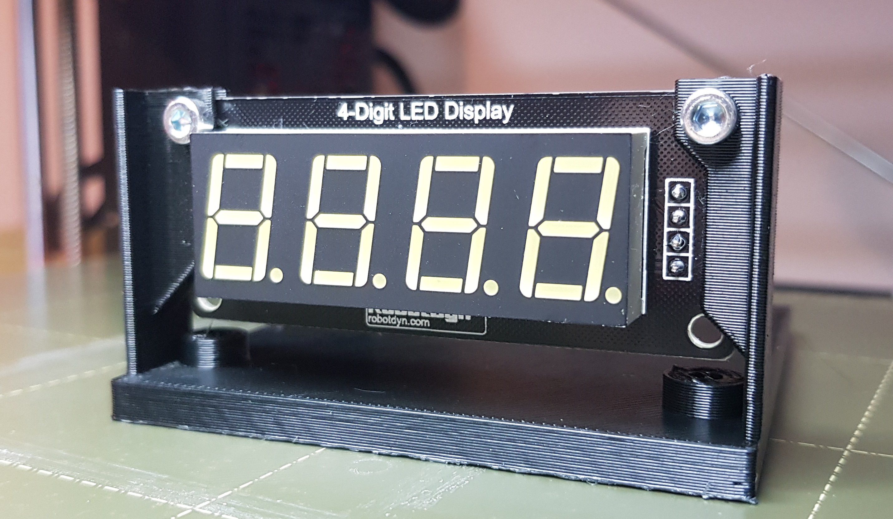
02/01/2021 at 18:16 • 0 commentsAs described in my last log, I decided to drop the MAX7219 and use the TM1637 LED driver instead. The reason is that it's a lot easier to find 4-digit seven-segment displays with this driver chip all in the same PCB, like this one from Robotdyn.
---------- more ----------After having ordered and received of a pair of displays, I started with the software.
Software
I wanted to keep the existing functionality as much as possible, including the support for MAX7219 (you never know if you need it some time later). So before adding TM1637 I refactored the code: I separated the MAX7219-specific code to a C++ class I called
Max7219Display, then extracted an interface (i.e. a C++ class with only pure virtual functions) out of it:struct SevenSegmentDisplay { /** Initialize the display */ virtual void begin() = 0; /** * Set the brightness from 0 to 255. 0 means off. * The display may use less precision. */ virtual void setBrightness(const uint8_t brightness) = 0; /** * Set the segment data. * * The array must be 4 bytes long for 4 digits. */ virtual void setSegments(const uint8_t digits[]) = 0; void clear() { const uint8_t empty[] = {0, 0, 0, 0}; setSegments(empty); } };Then I ensured all of the existing code only "knew" about this interface. Once done, it was easy to add support for the TM1637: I made a class called
Tm1637Displayand added the chip-specific code there. It's the only part of the codebase that talks with the TM1637 library.Hardware
The TM1637 module requires just four pins: ground, 5V, data I/O (DIO) and clock.
Because I don't have any more free pins in the Wemos D1 Mini, I'll use two of the three pins already used for the MAX7219: SPI MOSI as DIO pin, and SPI SCLK as clock pin.
I don't need to add new components in the schematic, but I don't need to remove any either. In particular the MAX7219 can stay where it is, soldered to my custom-made PCB. Because I'm keeping its LOAD pin tri-state, it will basically never be activated. If I want to replicate the circuit on one of the other PCB copies I have, I won't solder any MAX7219 of course.
I thought about making changes to the PCB. All the audio processing stuff (CPLD, VU meter, JTAG connector) can go away since I won't do any of this (playing around with that was awesome though!). The MAX7219 and the level shifters can now go away too. I could even drop the 3.3V regulator, the one built-in in the WeMos is enough for the only level shifter needed for the IR sensor. So the PCB could become a lot simpler and smaller. But should I really invest time to design a new PCB, order a new batch (while I still have 4 empty PCBs), wait for shipping, just to save some space? So I discarded the idea and kept what I already have, which is more than enough.
I had to make quite a few changes to the enclosure. The new module is smaller than the old one across all dimensions. I have to move its stand forward. And give room to the four solder pads on the right. I also wanted to use two of the four mounting holes. Here's the result:
![]()
A little desire of mine was to add some kind of color filter, so that the yellowish tint isn't visible while segments are off. It makes the whole thing look more professional too. For this display it was also a necessity, because it gives a very bright white even at low brightness levels!
It was actually quite hard to find a plastic gray filter ~1mm thick of 10x10cm or less. Online art shops didn't have anything like that. Plexiglas was only available from 3mm thick or more. Looking for gray or ND filter only showed expensive photography glass lens filters. It didn't help that I live in the Netherlands and I didn't know the correct search words in Dutch.
In the end I found a shop selling rolls of Oracal 8300 transparent cals with various colors. I found middle gray (#074) quite suitable. After shipping, I realized something pretty obvious: these cals are adhesive, meant to stick to another transparent rigid surface like acrylic or glass. I don't have any of that of course. So I made up for it by carefully sticking two patches of cal together, and trying to not capture air bubbles or dust in between.
I updated the 3D-printed enclosure to also accommodate the filter in front of the display, sliding it from the bottom and fixing it with some tape (not in pic):
![]()
Here it is, in its final shape. Really happy of the result:
-
Farewell, old display from 2001
01/30/2021 at 08:55 • 0 commentsThis project has (at least) one big shortcoming. But that same shortcoming was crucial to give me motivation to work on, and eventually complete, this project.
---------- more ----------I'm talking about the display. While it's true that you can build your own controller with just an ESP8266 and an IR receiver, it gets much easier to use with a display; especially if the controlled device doesn't have a display on its own (like the Samsung M7 Multiroom speaker I started with) or it's too far to be useable (like my new Hi-Fi system).
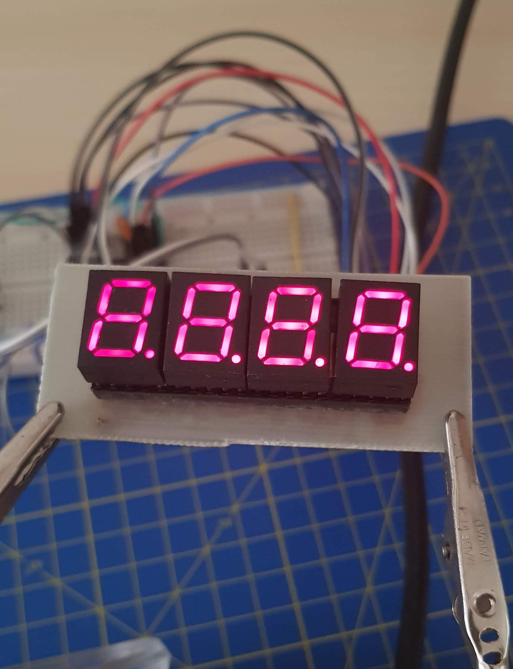
The display I used in this project is a special one, and for personal reasons.
![]()
It's made of four seven-segment LED displays in common-cathode configuration, mounted on a 40-pin DIP socket, soldered to a PCB I designed and etched at home, connecting together the anodes of each display in a matrix configuration, and making them available via a total of 12 wires. That PCB was the result of several personal accomplishments: learned how to use a schematic/layout editor like EAGLE; made my own PCB design; etched my PCB at home. I learned all this by myself, with all the contents I could get from a still young Internet back in 2001.
I was particularly proud of my solution of meandered tracks to connect single lines of pads in a single-sided PCB:
![]()
This display was just a test for a bigger project, but I didn't throw it out. I kept it despite my changes in life: moving city, doing university, moving country, work at small and big companies, getting married... It was just sitting in a drawer with other electronic components, and I used to take it out every once in a while and relive those times of teenage-nerd fun and excitement.
Soon after I decided to start this project, around January 2020, I wanted some display to show the current volume level, mute status, and wi-fi connection status. I soon realized that that display was just perfect: big enough to be visible from TV to couch, small enough to fit in an unobtrusive box. I already had a few MAX7219s to control the LEDs. With some restoration (lots of oxidization, some re-soldering required), that circuit came back to life after a 19-year hiatus doing some useful stuff again. In a way, seeing those blinking not-so-bright LEDs reassured me that I never really lost my tinkerer nature.
So I made the schematic, the firmware, and the 3D enclosure fit to accommodate this little relic. It was fun for an one-of-a-kind thing, but not so great if I'd really like others to replicate this project and benefit from it: I lost the EAGLE files long ago, the displays are out of production, the MAX7219 increases unit costs and PCB estate. While there are cheaper and better alternatives on the market, like this module from Robotdyn: four wires, serial communication, and you're ready to go. Much brighter too, and can go on for years.
And I started seeing the signs of age: some segments started going off and I had to tap the box to turn them on, like an old TV. Every time I opened the box, something else breaks. So I decided to not spend any more time in nostalgic mode and move on with more modern solutions. But I don't regret anything: I gave those memories the closure they deserve.
Farewell, old display from 2001, you served me well. -
Fix top enclosure
01/02/2021 at 15:29 • 0 commentsI updated the top enclosure design.
The hole for the USB port was a bit too much to the left, and it's now centered.
The side walls were a bit too thin (0.90mm). I initially made them that thin to use some snap-fit. But it wasn't necessary in the end: the print tolerances make enough extra width in both top and bottom enclosure to make the necessary friction. With 1.80mm walls the case is now stronger, and it's much easier to remove the supports without breaking it.
-
Power on the MusicCast device
01/01/2021 at 20:50 • 0 commentsJust merged a PR that also powers on the MusicCast device with the TV/Radio button.
Can be fetched here: https://github.com/egueli/SamsungM7_IR/releases/tag/v1.0.1
I'll also remove the old release's zipfile from this project; it feels like redundant work.
-
Completed... ish
12/31/2020 at 14:28 • 0 commentsAfter months of (slow) development, the project is good enough for me to be used every day without hiccups, except a small software fix and another one in the enclosure that I'm printing right now. Will post updates soon.
I'd love this project being used by others too. But I realize it may not be that easy. First, because I published this project here on Hackaday.io only yesterday and I still have to figure out a lot of things. Second, the firmware itself needs a few tweaks to be customized for an environment that's not like mine. A few things right off the bat:
- When it starts, it looks for a MusicCast device called "Living Room" in the local network. Alas I couldn't tell to just pick up any device, because it uses "_spotify-connect._tcp.local" as a mDNS service name and many non-MusicCast devices may respond to that. You can change the device name in src/discovery.cpp.
- The firmware assumes the TV is an LG, with its remote control sending specific IR codes. If you have a different model, you should change the IR codes in src/config.h. Which codes do you need? Open the serial console after the upload and watch for "[IR:xxxxxxxx]" text every time you press a button.
- The minimum/maximum volume levels are hard-coded to 1 and 161, that's good for my Yamaha R-N602 amplifier. Yours may need different values. Again, they can be changed in src/config.h.
- The firmware supports Samsung Multiroom and Yamaha MusicCast protocols, but only one at a time and it's configured for MusicCast at the moment. In src/config.h you can change that.
That's all for now.
SpeakerIR
Enjoying TV with a smart Hi-Fi or speaker? Use your TV IR remote to control volume, instead of having the other one always around.