 bobricius
First preview :)
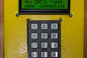
There nothing, just display and buttons ;)
- Display configuration
sudo apt-get install cmake
cd ~
git clone https://github.com/juj/fbcp-ili9341.git
cd fbcp-ili9341

mkdir build
cd build

cd fbcp-ili9341/build
rm -r *

cmake -DST7789VW=ON -DGPIO_TFT_DATA_CONTROL=25 -DGPIO_TFT_RESET_PIN=27 -DGPIO_TFT_BACKLIGHT=24 -DSTATISTICS=0 -DSPI_BUS_CLOCK_DIVISOR=6 -DUSE_DMA_TRANSFERS=OFF -DDISPLAY_ROTATE_180_DEGREES=ON ..

make -j
sudo ./fbcp-ili9341
For autorun on startup put this line before exit 0 in your sudo nano /etc/rc.local
sudo /home/pi/fbcp-ili9341/build/fbcp-ili9341 &
sudo modprobe -i uinput &
sudo python /home/pi/keyboard/keyboard.py &
sudo setfont /usr/share/consolefonts/Lat2-Terminus20x10.psf.gz &
These lines are in my sudo nano /boot/config.txt file:
hdmi_group=2
hdmi_mode=87
hdmi_cvt=320 240 60 1 0 0 0
hdmi_force_hotplug=1
Change in driver before compilation st7735r.h
#if defined(ST7789) || defined(ST7789VW)
#define DISPLAY_NATIVE_WIDTH 240
#define DISPLAY_NATIVE_HEIGHT 320
#elif defined(ST7735R)
#define DISPLAY_NATIVE_WIDTH 128
#define DISPLAY_NATIVE_HEIGHT 160
#elif defined(ST7735S)
Change in driver before compilation st7735r.cpp
#ifdef ST7789
    // The ST7789 controller is actually a unit with 320x240 graphics memory area, but only 240x240 portion
    // of it is displayed. Therefore if we wanted to swap row address mode above, writes to Y=0...239 range will actually land in
    // memory in row addresses Y = 319-(0...239) = 319...80 range. To view this range, we must scroll the view by +80 units in Y
    // direction so that contents of Y=80...319 is displayed instead of Y=0...239.
    if ((madctl & MADCTL_ROW_ADDRESS_ORDER_SWAP))
    //  SPI_TRANSFER(0x37/*VSCSAD: Vertical Scroll Start Address of RAM*/, 0, 320 - DISPLAY_WIDTH);
        SPI_TRANSFER(0X37,0,0);
#endif
- Keyboard reading is based on:


 Ron Grimes
 PixelCircuits
 daking1
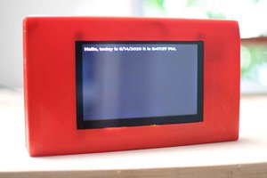
 Travis Bumgarner
I want to see this but with a pico :)