Close
0%
0%

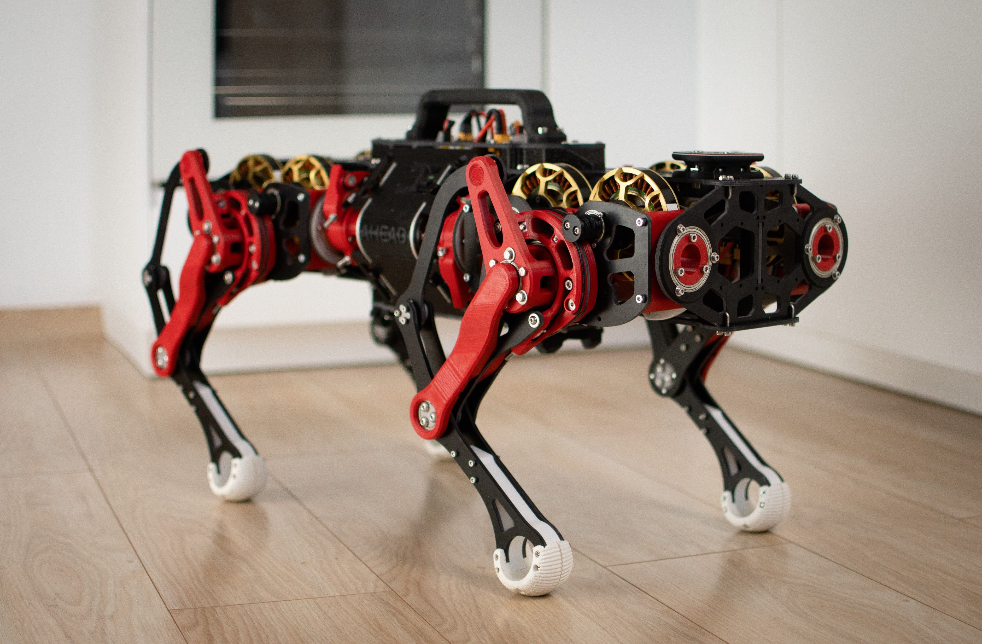
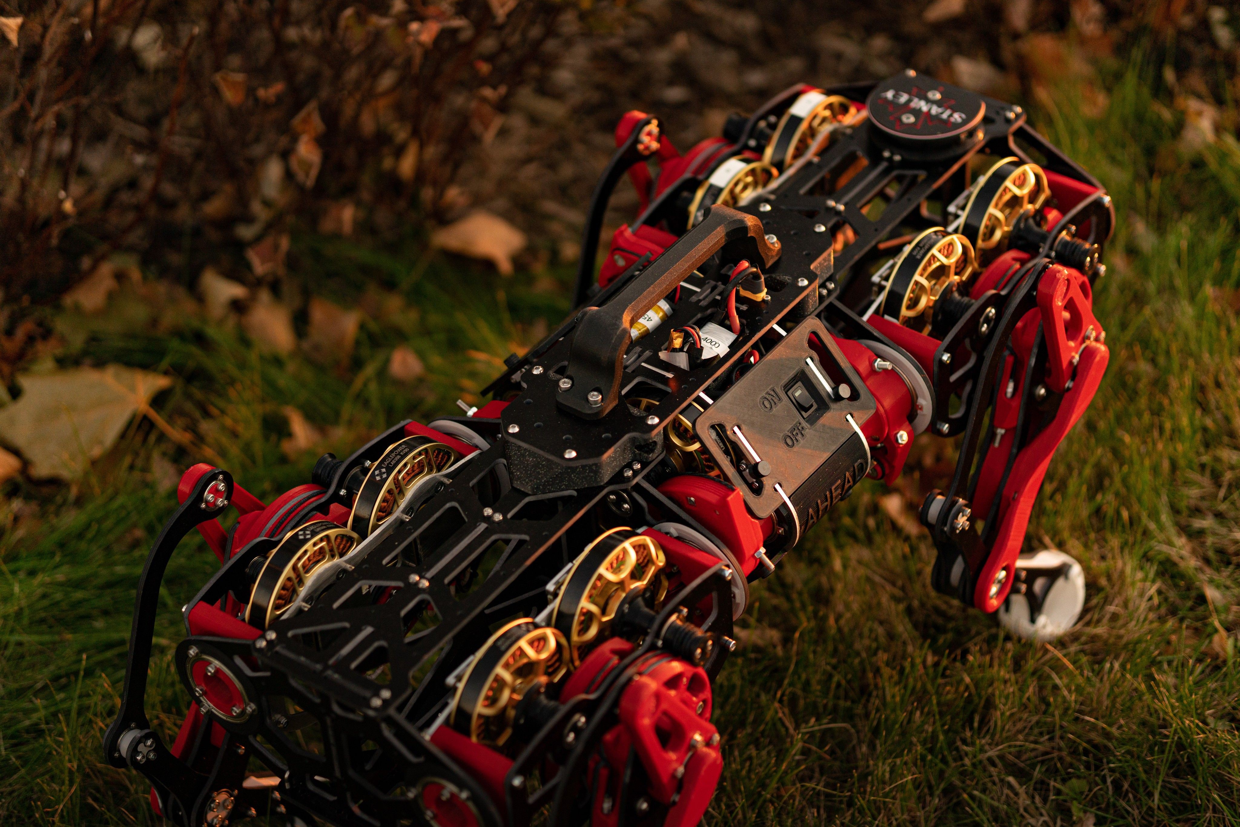
Stanley - the capstan based quadruped kit

A maker friendly capstan based BLDC driven quadrupedal robot kit.

Similar projects worth following
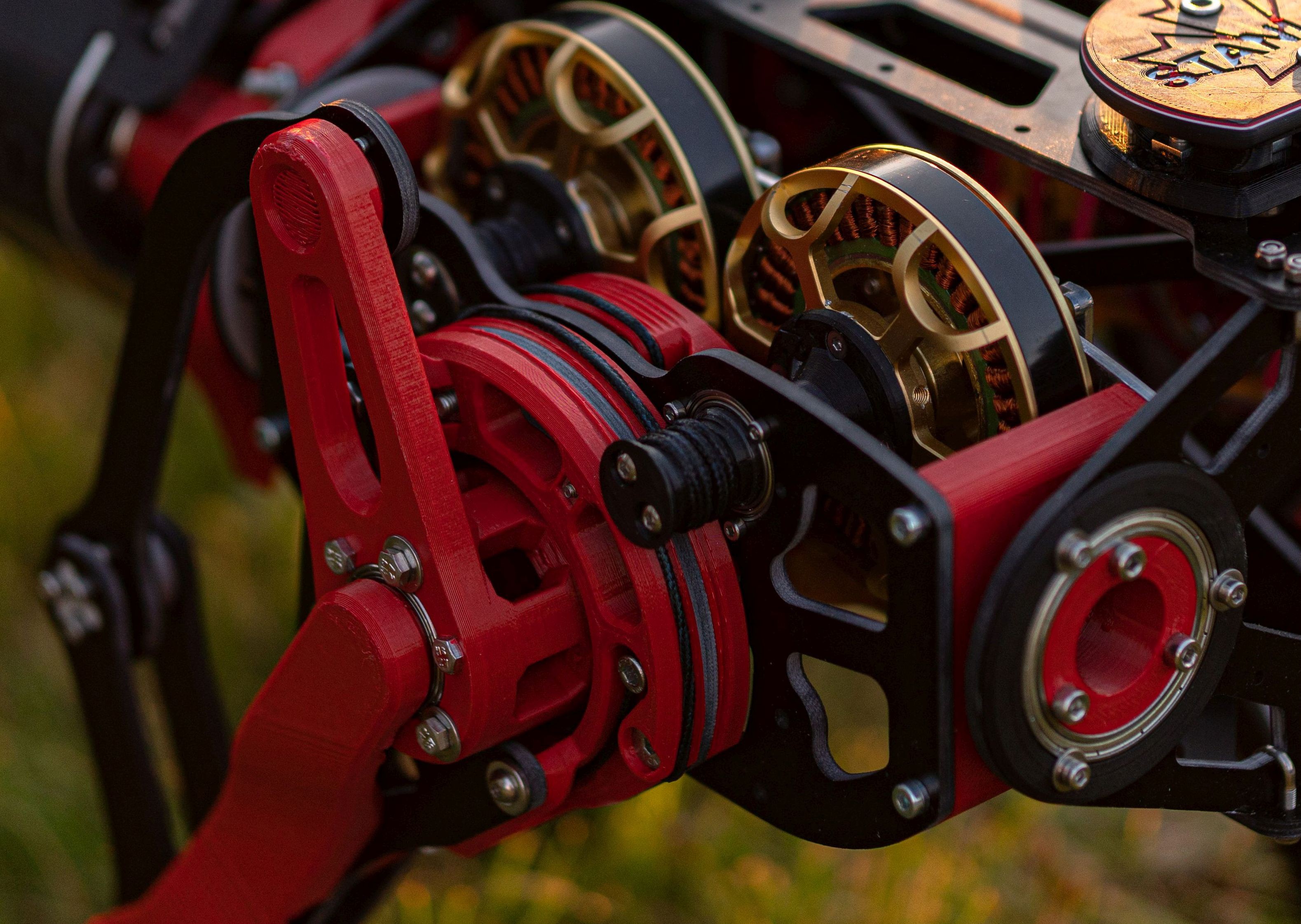
Our goal is to create a quadruped kit close to the performance of the MIT mini cheetah as. The use of Capstan Drive's allowed us to lower the price of the entire build. Two fabrication techniques are being used - FDM 3D printing which almost every maker now has access to, and 2D milling in FR4 - which is less available, but it is cheap to order these parts in a local shop. Drivers used are mjbots moteus r4.5, the two choices for the main computer are an Rpi4 or UPBoard . The motors are 90KV 8308's

The current stage of the project:

Done:

  1. Design a single capstan reducer and build a test stand for it - perform tests and improvements.
  2. Design and build a 2Dof leg - with the knee and hip joint.
  3. Write a python script for communication with the moteus r4.5 controllers over the USB-CAN_FD adapter
  4. Solve inverse kinematics and scripts for jumping and various other demonstrations.
  5. Perform testing on the 2Dof leg - continuous jumping for 1h - inspect, iterate.
  6. Design and build a 3Dof leg - adding the ab/ad joint.
  7. Perform testing on the 3 Dof leg - continuous jumping for 1h between randomly chosen points.
  8. Make design corrections based on the test and retest. Also perform mass reduction improvements.
  9. Design the chassis.
  10. Print a mock-up of the chassis before ordering the "real thing" in FR4 to verify the design .
  11. Get all FR4 Parts and assemble The First Stanley.
  12. Lay down cables.
  13. Get the internal CAN communication working.
  14. Get the Xbox360 Controller working with RPi4B.
  15. Solve inverse body kinematics, make a demo.
  16. Create a parametric step trajectory generator, make Stanley walk for the first time.
  17. Tune the walking algorithm.
  18. Add jumping functionality.
  19. Test different types of cables, choose the best one.
  20. Make assembly improvements.
  21. Create prototype payloads for JetsonNX and Intel cameras.
  22. Create side covers that better protect the insides of Stanley
  23. Redesign cable tension system for easier assembly.
  24. Create assembly tools.

To do:

  1. Increase reduction ratio to 1:8.
  2. Make Stanley’s legs longer.
  3. Make the AbAd actuator more compact.
  4. Introduce new, lighter motors (probably).
  5. Make more space inside Stanley for compute and batteries.
  6. Further assembly improvements.
  7. Reduce the number of types of screws used in the design
  8. Develop Mobile Application to control .Stanley missions.
  9. Create SDF for simulations.
  10. ...

  • Leg design changes: assemblability and maintenance improvements

    Gaelle06/02/2022 at 11:38 3 comments

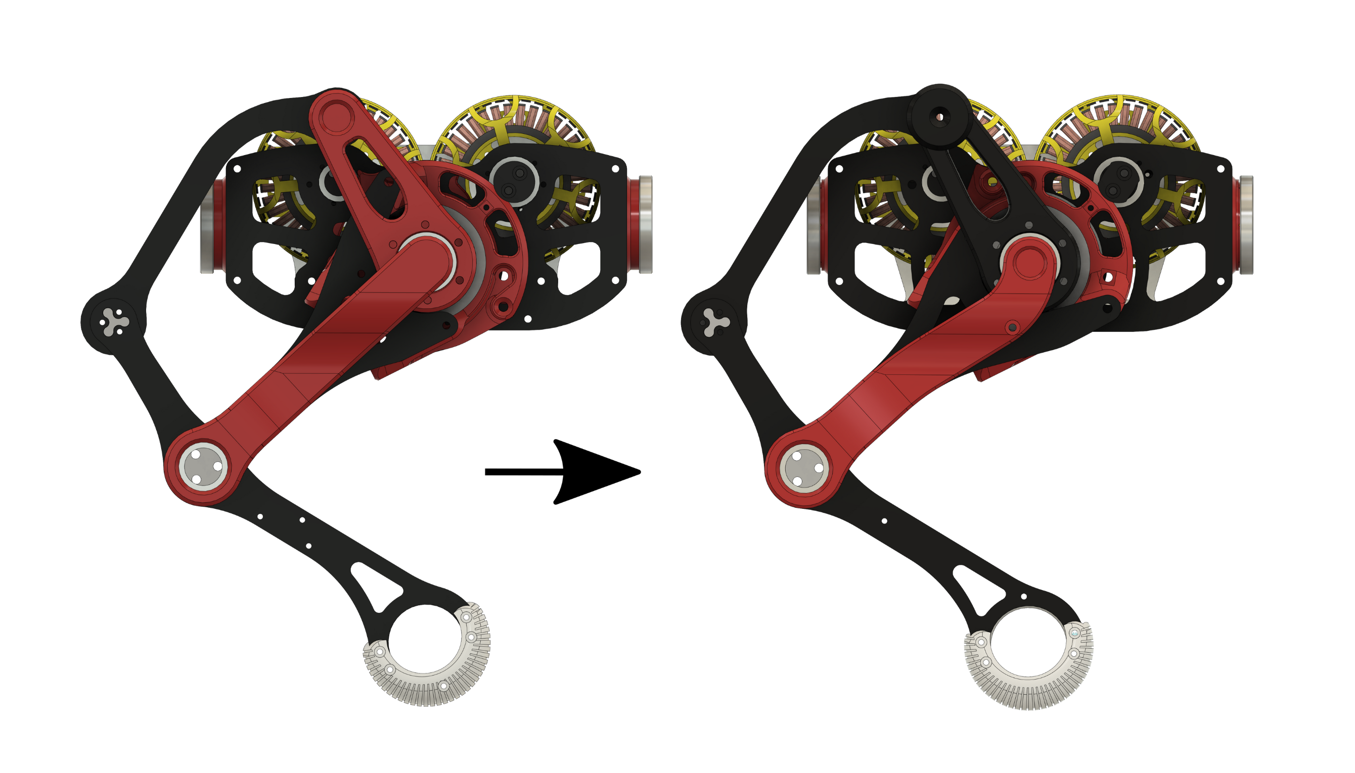
    We made multiple changes which aimed to improve the assembly experience when building Stanley. The most substantial one was the decision to flip (mirror) the Cable mechanism of the hip.

    This change brought a few key benefits:

    • The Femur Scaffolding (grey part along the femur) was straight on the old design and has a bend in the new design. It is now mounted with fewer, but better-placed screws, which means it provides better support and a small mass saving.
    • There is significantly better access to hip mechanism cable tensioning.
    • The assembly process of the hip cable mechanism is less fiddly.

    Other changes include:

    • Reducing the number of screws per leg: 12 fewer screws per leg needed!
    • Rotating the floor a bit more downwards so it is facing the ground at a more universal angle
    • Improving access to cable tensioning nuts
    • Making the entire leg assembly 6 mm shorter (eliminating some dead space in the ABAD mechanism)

  • What was most likely to break and how we prevent it

    Gaelle05/19/2022 at 21:37 2 comments


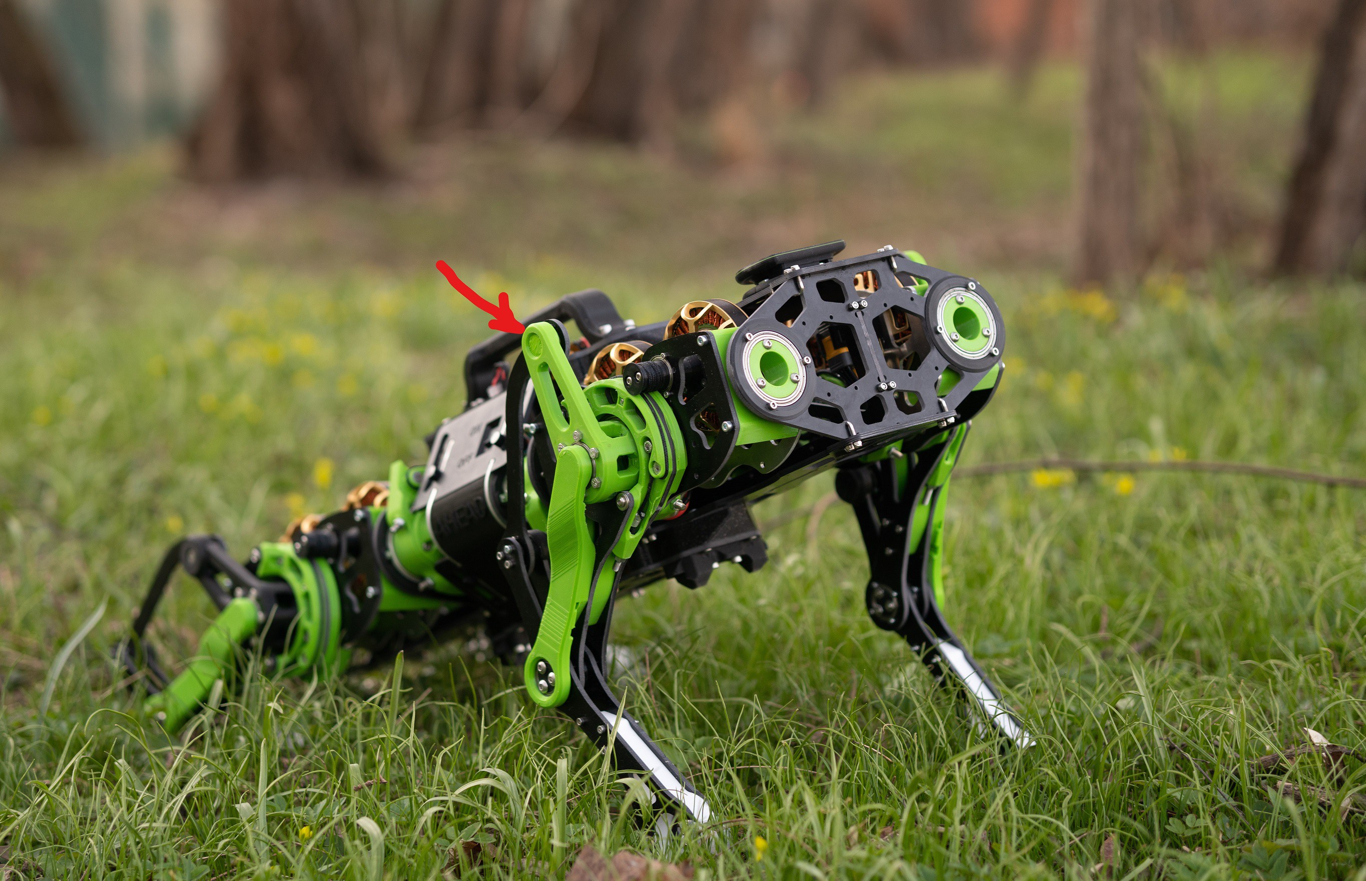
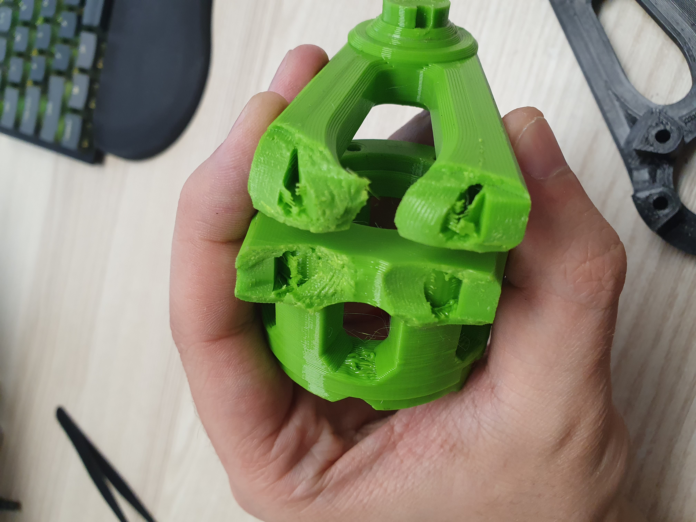
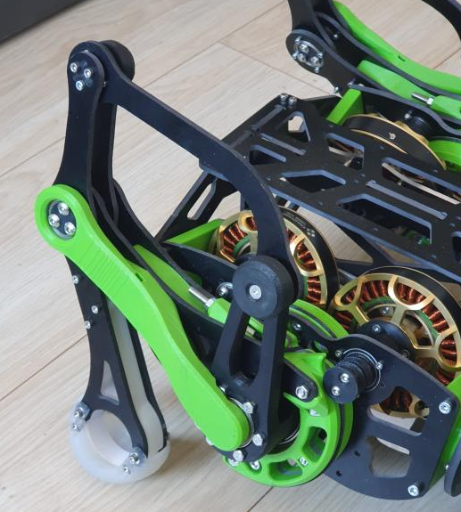
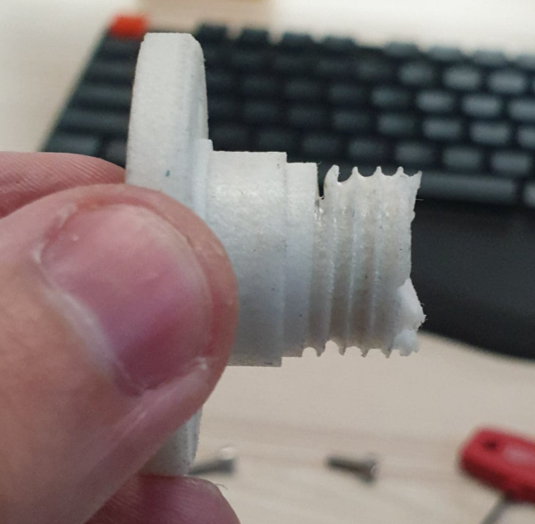
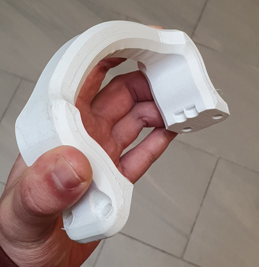
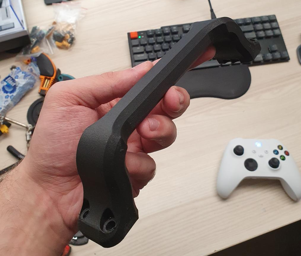
    In our testing so far, we found that the Crank (see image below) is the part of Stanley’s leg that is the easiest to break.

    When the robot falls on its side, strong impacts on the tip of the crank are likely to occur, which causes it to snap.

    As seen in the picture above the snap occurs across layer lines, so layer adhesion does not play a role here.
    We took two preventive measures against this. First - we switched the material we use from PET-G to Polycarbonate.

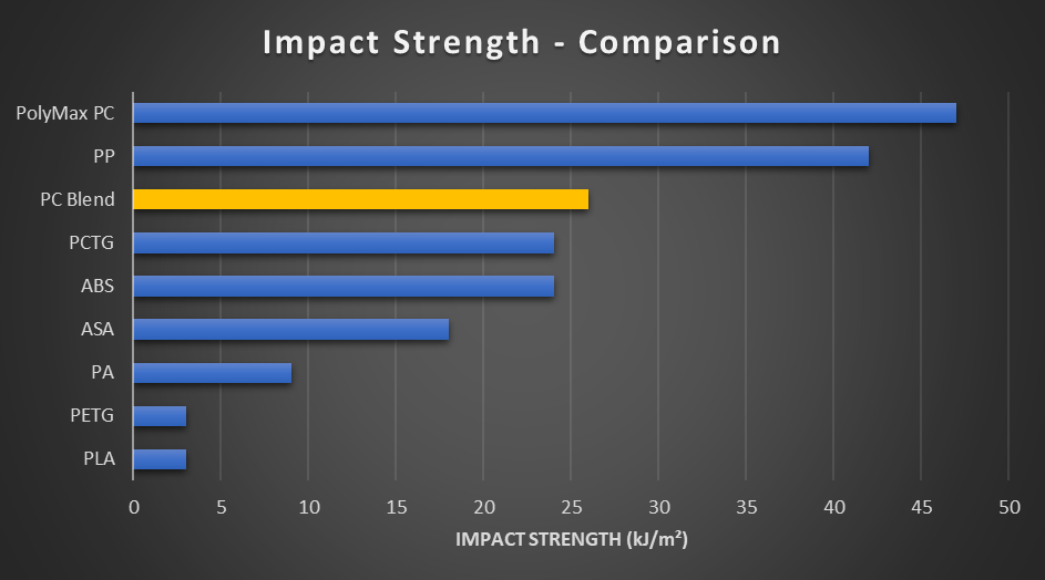
    Source: https://www.cnckitchen.com/blog/prusament-pc-blend-review

    Not only does Polycarbonate have a 40% higher tensile strength than PET-G, but its impact strength is an order of magnitude better, which makes it a perfect material for this demanding part.

    The second improvement was the introduction of a TPU (Fiberlogy MatteFlex) bumper - to soften the impacts and prevent scratching. So far we haven’t seen this setup break, but we keep testing, and keep improving!


  • If the shoe doesn't fit... redesigning Stanley's feet

    Gaelle05/05/2022 at 14:23 0 comments

    Stanley’s feet design needed an update.

    So far we had been using Fiberlogy Fiberflex 30D to print Stanley’s feet in two parts.

    Although we like this filament a lot, there are inherent limitations to how soft and sticky a 3D printing filament can be. 

    These limitations are caused by the construction of FDM extruders. Even an extruder that is well optimised for flexibles, like the E3D Hermera - still needs to grab onto the filament, push it through a metal tube and fight the backpressure created by the small nozzle hole on the other side.

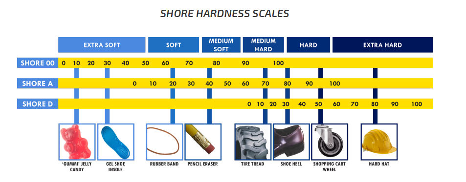
    This means that the softer this filament is, the easier it will be for it to buckle and press against the wall of the tube, and the higher its coefficient of friction the more resistance this pressure will cause. That is why the softest filaments on the market are in the Shore 75~85A (20~30D) range.

    This limitation does not apply to castable silicone rubbers. These come in hardness levels all across the Shore hardness scale. We made an educated guess and picked a silicone rubber at the Shore Hardness of 25A for Stanley’s feet.

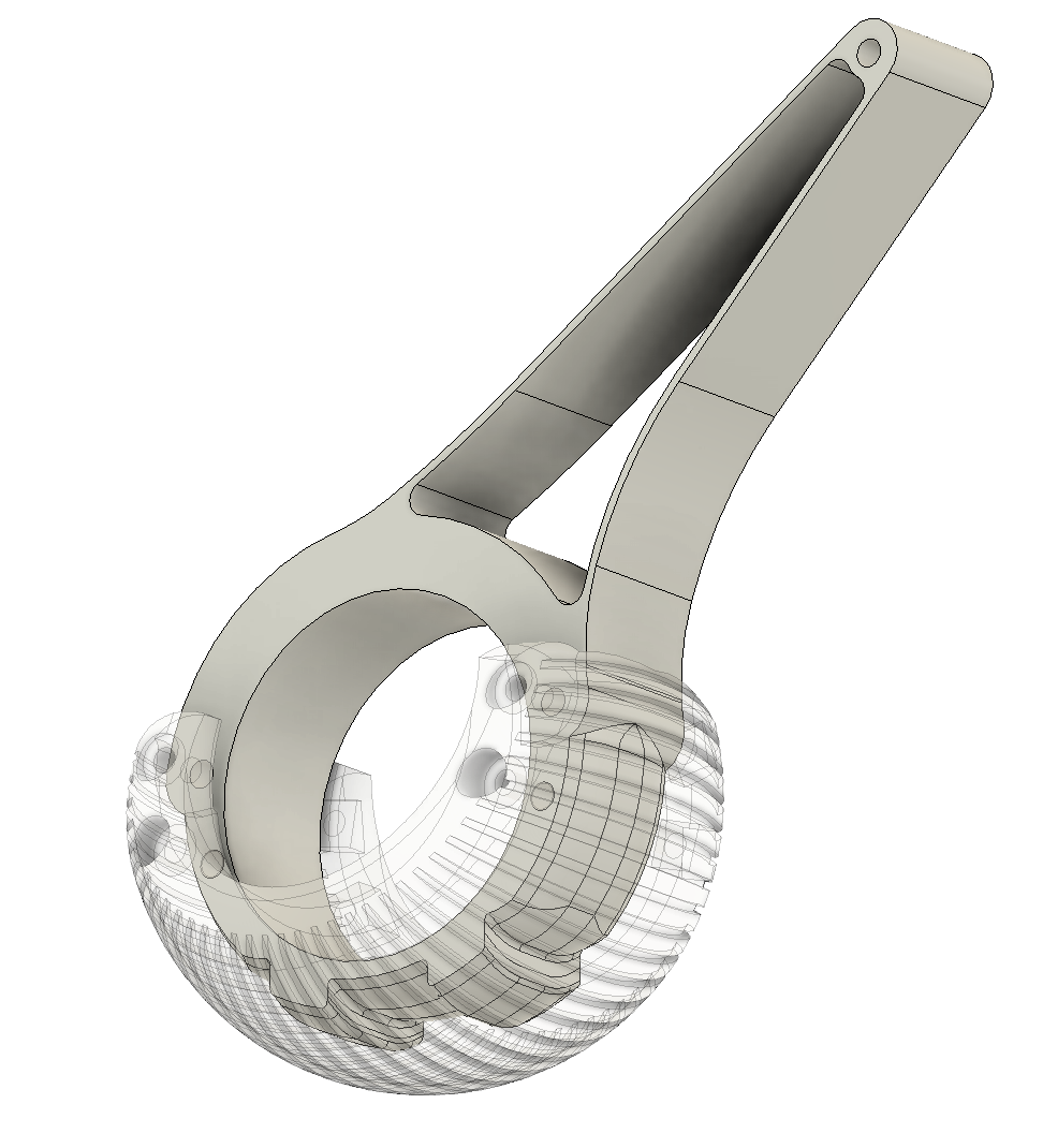
    The silicone rubber is so soft that it needed scaffolding in order not to move around too much. We designed a scaffolding that includes two ridges that prevent the rubber from sliding along the scaffolding during forwards acceleration.

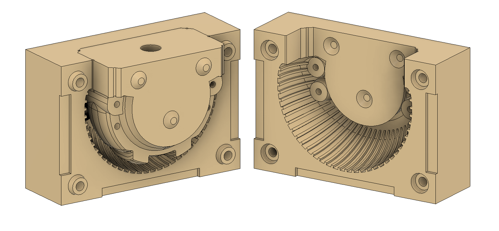
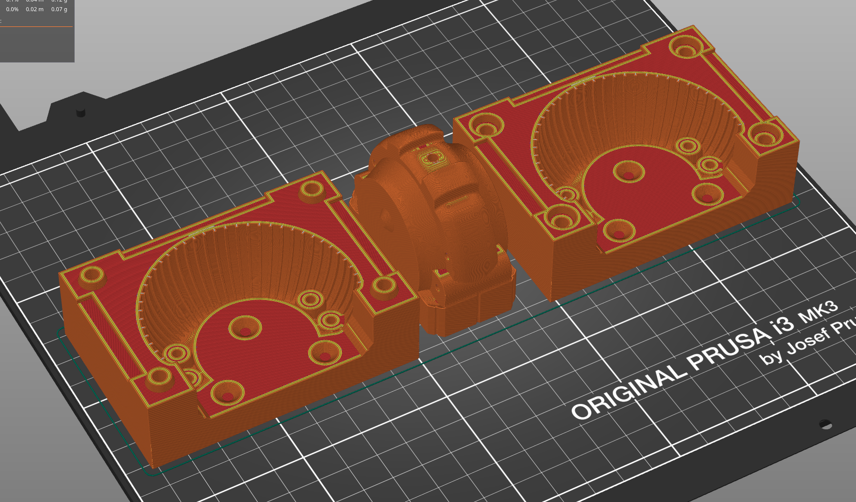
    Now when this was ready we needed a mold! We designed it in 3 parts:

    That print like this:

    We use 4x M4 screws to assemble the mold and we also push 4x steel rods into it, which act as the negative for screw holes in the feet.

    We use a big syringe to inject the silicone into the mold through the top hole.
    The 3 conical features on the central part of the mold act as locating features, improving assembly precision. The cones around M4 screw holes serve the same purpose. The recessed tabs around the edges make opening the mold easier.

    Have a look at the very satisfying process of demolding Stanley's rubber feet in this short video:

  • On the lookout for the best filament for small drums.

    Ahead04/12/2022 at 03:47 1 comment

    The Small drums of Stanley’s Capstan mechanisms are experiencing the highest loads out of all the printed parts on the robot.

    That places some high demands on the filament we print them with. We started with just basic PET-G which failed a few times with the earliest designs.

    With geometry improvements, we were able to get it to a state where it was no longer failing, but we felt that the safety margin was not high enough.

    We first tested Nylon, Nylon blended with Carbon Fiber and Nylon Blended with Glass Fiber ...

    Although they did not break along layer lines as PET-G did, they showed definite signs of wear. The grooves were getting worn in, and the Nylons with additives behaved a bit like a sponge that is getting pressed in.

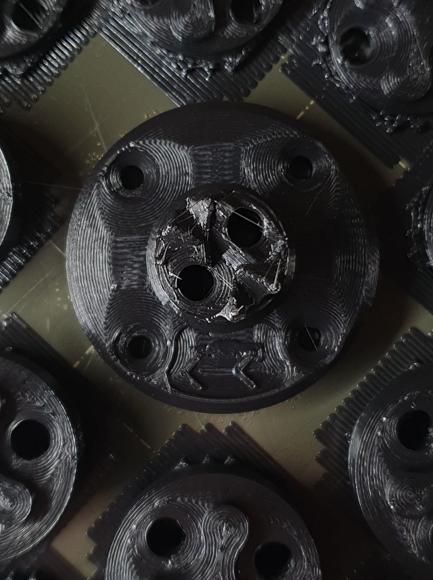
    Then we came across the Prusa PC Blend, which turned out to be ideal for our application. It is strong both across and along layer lines. It is stiffer than Nylon, but not so stiff that it would shatter easily like PLA.

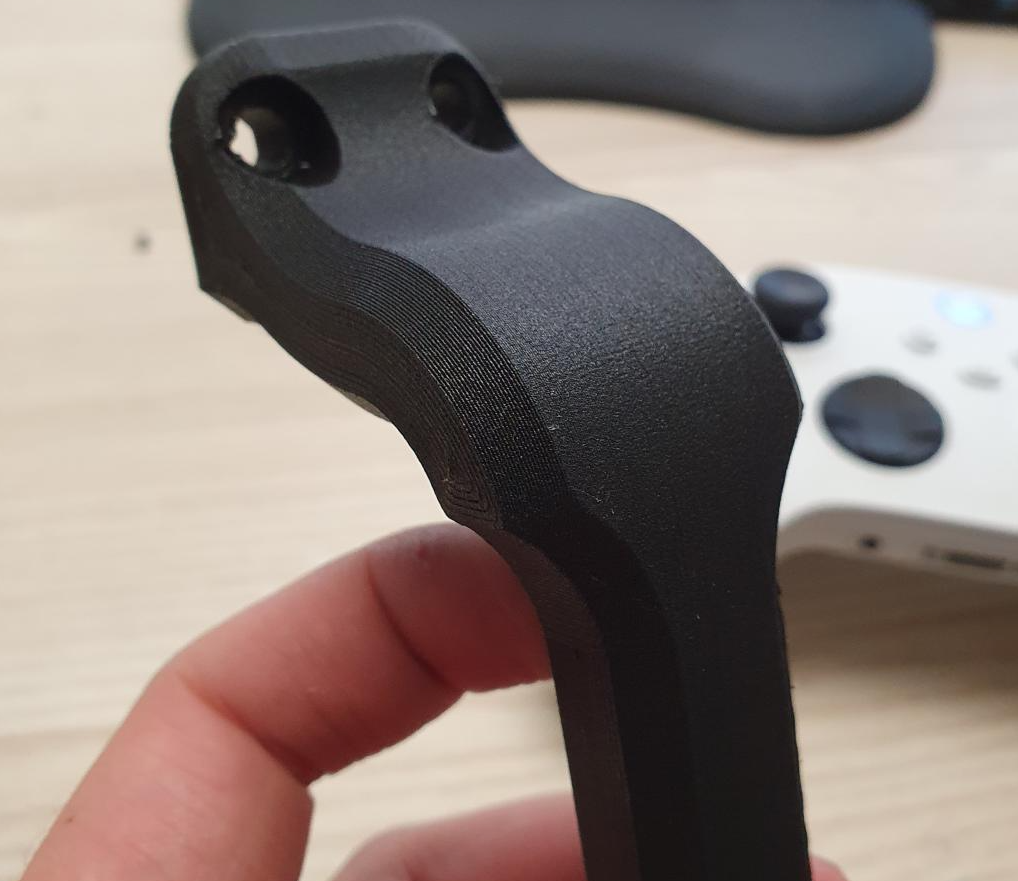
    It is decently easy to print and with Magigoo for Polycarbonate it prints really reliably. Since we started using PC Blend for our small drums we haven't seen any one of them break nor show any significant signs of wear. Here’s an image of the PC Blend print:

    More to come :)

  • We built a second prototype of Stanley and offered it to a charity auction!

    Damian Lickindorf03/23/2022 at 21:15 0 comments

    https://www.bidsfortheball.ca/lite-ui/?controller=lots&action=showLot&id=5

    The RBC Innovators ball is a celebration in support of sparking curiosity and delivering innovative and accessible science experiences at the Ontario Science Centre.

    We were inspired by this mission statement and decided to donate the second Stanley prototype we made to the Science Center for their fundraising event. Our goal was to inspire young generations to dive into robotics and have a better understanding of how quadrupeds work.
    We were really lucky to be present in Toronto for the event and to introduce Stanley to Dan Riskin! You can watch a replay of the event on Youtube (Stanley makes a come back at 45’19” and 1:00’00”)

    This specific Stanley prototype was modified especially for the event with some special touches like the signature colour red and a maple leaf design on the front puck.

  • The handle - on the lookout for the perfect rubber!

    Damian Lickindorf03/18/2022 at 05:48 0 comments

    For the handle on Stanley, we started with just plain PET-G, but we soon realized that it would break every time Stanley fell over and landed upside down. After that, we printed the handle with FiberFlex 30D rubber which turned out to be too much of a “wet noodle”.

    And then Fiberlogy released the MatteFlex 40D! We ordered a spool as soon as we it became available and we’ve been extremely happy with the results right away!

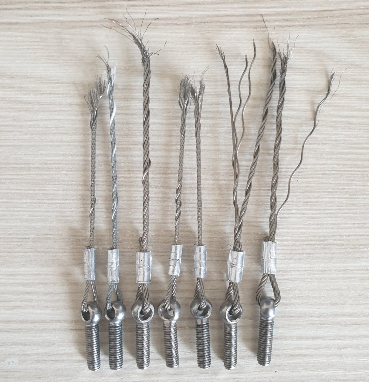
  • The day we realised Stainless Steel Cables BREAK.

    Ahead03/16/2022 at 04:08 2 comments

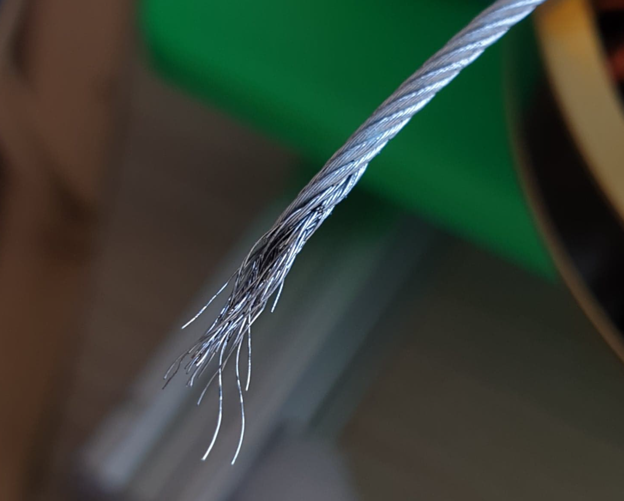
    After extensive “on stand” testing and the first few days of having fun with fully assembled Stanley, we felt pretty confident about the stainless steel cables. But we were wrong.

    Within a few days - after we Started implementing jumping - Stainless Steel Cables started breaking one after another.

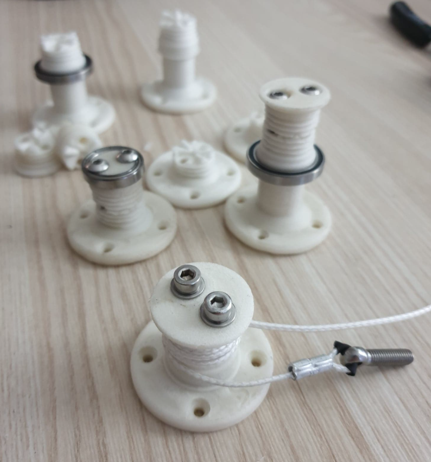
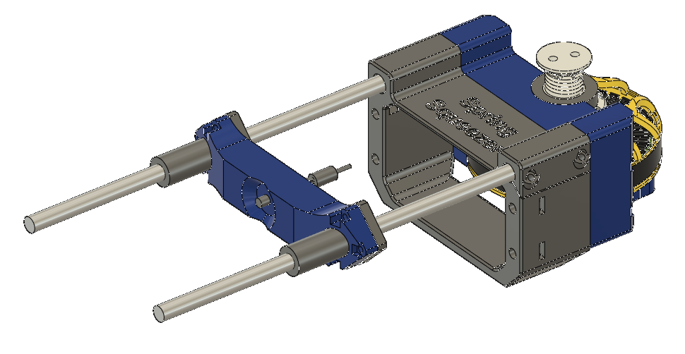
    We did tests with thicker cables and different cable constructions. We even built our own machine for testing Cables - the SpringSqueezer (link to the Github repo) :

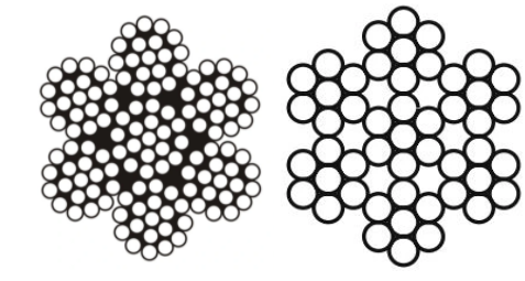
    We hoped that a thicker cable or one with more and thinner strands would solve the issue:

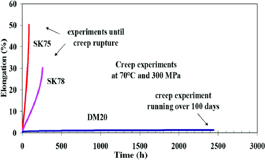
    But this wasn’t enough. We needed to move to a synthetic cable. After doing the research we decided to go with Dynamica DM20 - a strong synthetic fibre with very low creep.

    Now all Stanleys we build have a custom DM20 rope in their capstan mechanisms.


    And it just works! :)

  • Proper walking!

    Damian Lickindorf03/13/2022 at 17:10 0 comments


    In this second “catching up post” we show you some better walking! This time battery-powered, untethered, with much softer PD settings


    We took Stanley to a rooftop terrace to experiment on some less even terrain. At this point we are running a controller that does not make use of the ground reaction forces.


    Stanley’s mechanical cable-driven quasi direct drive actuators allow for great high-acceleration and high-frequency performance. We’re showcasing it here with a “spin in place” motion. Stanley is able to do a full 360deg rotation per second - 60RPM!

  • ​We are back!

    Damian Lickindorf03/09/2022 at 22:38 1 comment

    Hi!
    We are getting back to posting about Stanley here. We’ll start by getting up to speed with some milestones we achieved a while back and we’ll get to present ones very soon so stay tuned! First, take a look at Stanley Standing up for the first time and having a good stretch here:


    You can see here the wide range of motion Stanley is capable of. Achieving that was the next step after solving inverse kinematics for a single leg. Body kinematics is a layer on top of leg kinematics that calculates the Cartesian position of each leg tip needed to achieve the commanded position of Stanley’s body. That leg tip position is then fed into the algorithm for leg inverse kinematics and that’s how we get positions for each of the 12 motors.

    After that it came time for Stanley's first steps:


    The walk here is still pretty clumsy - slow and jittery. Stanley is walking tethered and the lab PSU is a limiting factor (although the PSU could easily handle average power consumption, the high momentary peaks were overwhelming it). PD parameters at the time were way too stiff (P was too high) and that is what made the robot so bouncy.

  • Inverse kinematics controlled with a gamepad

    Damian Lickindorf04/04/2021 at 01:07 0 comments

View all 19 project logs

Enjoy this project?

Share

Discussions

santos137 wrote 06/02/2024 at 18:39 point

Hi Damian, Long using Capstans to convert Power Kite grunt to high-speed generator driving. Also developing air-muscle robots with capstan elements. Always looking for similar cases and talent.

  Are you sure? yes | no

kenchalk wrote 03/06/2024 at 21:01 point

are you still planning to release the STL and CAD files?

  Are you sure? yes | no

Dimitri wrote 04/04/2022 at 18:33 point

Love your use of cables.  Jacketless provides a bit less hysteresis in my experience. M-Rig Max has worked better than the Mastrant antenna support line.

  Are you sure? yes | no

elpidiovaldez wrote 01/23/2022 at 15:01 point

Super impressive design and amazing performance ! You put a lot of thought into the choice of capstan drives (I read the exchange with @David Greenberg ), but you did not mention belt drives as an alternative.  AFAIK these are zero backlash, very quiet and probably have the advantage of being more conventional technology.  Why did you reject them ?  I am thinking capstan drive might be more compact/lighter; or perhaps you can tailor the torque profile by using a non-circular capstan...

  Are you sure? yes | no

rraetz wrote 08/11/2021 at 06:56 point

Amazing project, but a bit disappointing that you don't release any files... Are you planning to monetize it or is there any other reason? 

  Are you sure? yes | no

Ahead wrote 10/26/2021 at 01:03 point

We are working on a kit and organizing new material.  We will be releasing some files at one point.

  Are you sure? yes | no

jnesselr wrote 08/07/2021 at 18:11 point

Apparently the files existed and were then removed at some point? What's the reasoning behind that? I'd love to look at the files in a bit more detail. It looks like you might be using Fusion 360, is there a way to look at the entire file/assembly of that?

  Are you sure? yes | no

Damian Lickindorf wrote 08/07/2021 at 19:01 point

nope, the full design was never published.

  Are you sure? yes | no

jnesselr wrote 08/07/2021 at 19:10 point

Is there any particular reason why? ie, why not open source it so others can build it.

  Are you sure? yes | no

ntrewartha wrote 08/07/2021 at 11:28 point

Is there a kit available - I have no 3D Printer?

  Are you sure? yes | no

Ahead wrote 10/26/2021 at 01:04 point

We are working on a kit and we will be announcing something soon.

  Are you sure? yes | no

Tor wrote 08/06/2021 at 16:03 point

I love this project. Great work so far.

  Are you sure? yes | no

tuban96 wrote 05/14/2021 at 15:42 point

Any news on this project? I see there are no [longer] FIles available.

Can each leg rotate about the body axis independently? In the video, they all move together, but it seems like maybe they can.

  Are you sure? yes | no

abhiramrayadurgam12345 wrote 04/13/2021 at 16:45 point

what is the estimated total budget for this project?

  Are you sure? yes | no

fox007ggr wrote 01/29/2021 at 01:28 point

What is the name of the project on GitHub?

  Are you sure? yes | no

marazm wrote 01/10/2021 at 10:49 point

Jaki ma udzwig ten robot. Da się nim przenieść powiedzmy lekarstwa, albo wodę? wystarczyłby np. 2 litry wody + kanapka. Wtedy można było by to coś wykorzystać do transportu a ludzie zapewne chieli by zając się programowaniem. Gotowe moduły mógłbys sprzedawać jak Józef Prusa swoje drukarki

  Are you sure? yes | no

Jamie McLaughlin wrote 01/09/2021 at 10:35 point

Amazing project!  Are you planning on making the models available at some point?  I'd love to experiment with the design.

  Are you sure? yes | no

Damian Lickindorf wrote 01/14/2021 at 14:35 point

Please read the "Files:" section of the Description

  Are you sure? yes | no

Nick wrote 07/31/2021 at 06:56 point

There are no Files in the 'Files' section ...

  Are you sure? yes | no

Damian Lickindorf wrote 07/31/2021 at 16:13 point

@Nick that comment is out of date, files for this project will not be released.

  Are you sure? yes | no

Nick wrote 08/09/2021 at 00:49 point

That is disappointing to hear that they wont be released. It looks like an awesome project.

  Are you sure? yes | no

David Greenberg wrote 01/08/2021 at 17:50 point

I really like your design. Do you have any posts I could read about why you chose to use capstans over wobblers?

  Are you sure? yes | no

Damian Lickindorf wrote 01/08/2021 at 18:21 point

Wobblers?! 

  Are you sure? yes | no

David Greenberg wrote 01/08/2021 at 19:01 point
Haha, it's a funny name I've heard is slang for cycloidal gearboxes, another small way to get a big reduction. I know that harmonic drives (which now sums up the 3 compact low-to-zero backlash gearboxes I know of) can be annoying due to the constantly changing flexion of one component, which can drive up costs. I think yours is the first capstan quad I've seen, and I'd love your thoughts on why capstans over cycloidal drives. I can send you some links to cycloidal drive quads if you haven't seen that design.

  Are you sure? yes | no

Damian Lickindorf wrote 01/09/2021 at 01:16 point

@David Greenberg You could compare against many things, cycloids aren't even a worthwhile comparison cause the range of reduction ratios they offer has very little overlap with what u get with capstans. First the ratio - you need less than 1:9 to have a proper Quasi Direct Drive actuator, to achieve the torque transparency required to apply advanced controllers like the MIT mini cheetah one. (this is not true for all scales, but at this scale it is). So here cycloids are out of question already - just because of the ratio - they are also bad for many other reasons I won't get into. The only worthwhile comparison is to the planetary gearboxes in the actuators used in MIT mini cheetah and all similar bots. A planetary reducer is a better solution, it might be the best available - but only if you can fabricate your bot in metal. I decided to limit myself to 3D printing - and when we consider 3D printed planetary gearboxes - they would need to be really bulky, contain a lot of bearings and would wear quickly, plus will never be truly 0 backlash. A Cable drive can be as efficient as a planetary (also as torque transparent) - and at the same time, it does not suffer because of the limits of 3D printing. There are no contact spots that are under loads as high as the loads on teeth of a planetary gearbox. Thanks to this a highly torque transparent yet lightweight and robust to high dynamic loads can be manufactured using only 3D printing.

  Are you sure? yes | no

David Greenberg wrote 01/09/2021 at 01:20 point

Your reasoning makes a lot of sense. If you have any references on other downsides of cycloids, I'd be interested in reading, especially as to whether the downsides are fabrication or control related.

  Are you sure? yes | no

Damian Lickindorf wrote 01/09/2021 at 01:54 point

@David Greenberg the downsides are mainly low efficiency, and high massif higher efficiency is attempted (you could easily fit 50 bearings into a cycloidal gearbox if you want all contact to be rolling contact). I have experience making cycloids, they are good for robotics, even cobot-style robotics - but legs need much more than that in terms of torque transparency.

  Are you sure? yes | no

rraetz wrote 01/08/2021 at 09:00 point

This is amazing! I had a very similar design in my mind for a long time, but never had the time to realize it. I'm an engineer working in haptics where capstan drives are used quite often and I am conviced that they are very nicely applicable to quadruped robots. So I am really stoked to see your amazing implementation of this kind of transmission. Looking already forward to seeing your next progress update! 

  Are you sure? yes | no

ekaggrat singh kalsi wrote 01/08/2021 at 00:29 point

really cool work . !i wish i could afford to make one :(

  Are you sure? yes | no

Damian Lickindorf wrote 01/08/2021 at 02:04 point

I did my best to go as low with the price as i could, while still making a true high performance BLDC based quadruped. Below ~2400usd you need to go with hobby servos or dynamixels. There are also cheaper bldc options if you're willing to solder your own ESC's - take a look at the open dynamics initiative 

  Are you sure? yes | no

Dan Maloney wrote 01/07/2021 at 17:24 point

Nice design, I appreciate the attempt to keep it affordable.

  Are you sure? yes | no

Damian Lickindorf wrote 01/08/2021 at 02:04 point

Thanks :D was trying my best! 

  Are you sure? yes | no

Similar Projects

Does this project spark your interest?

Become a member to follow this project and never miss any updates