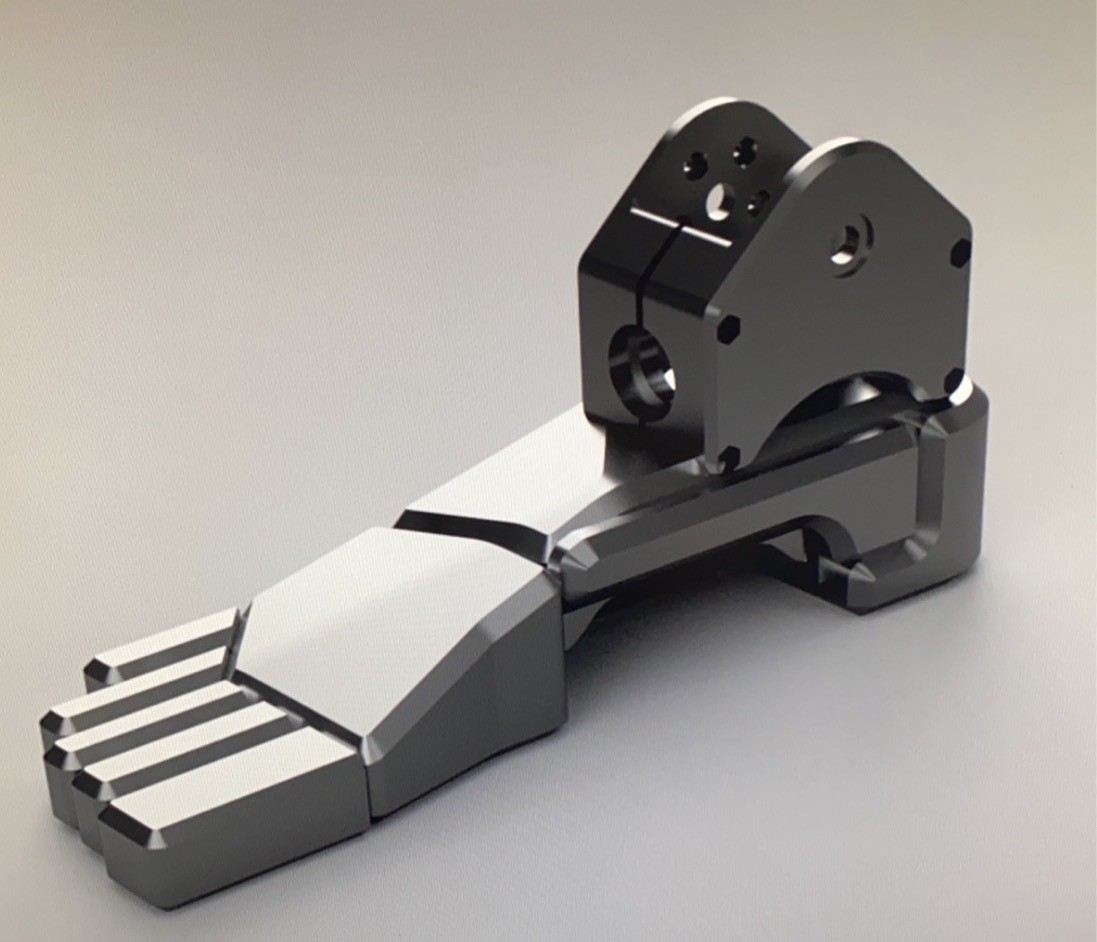
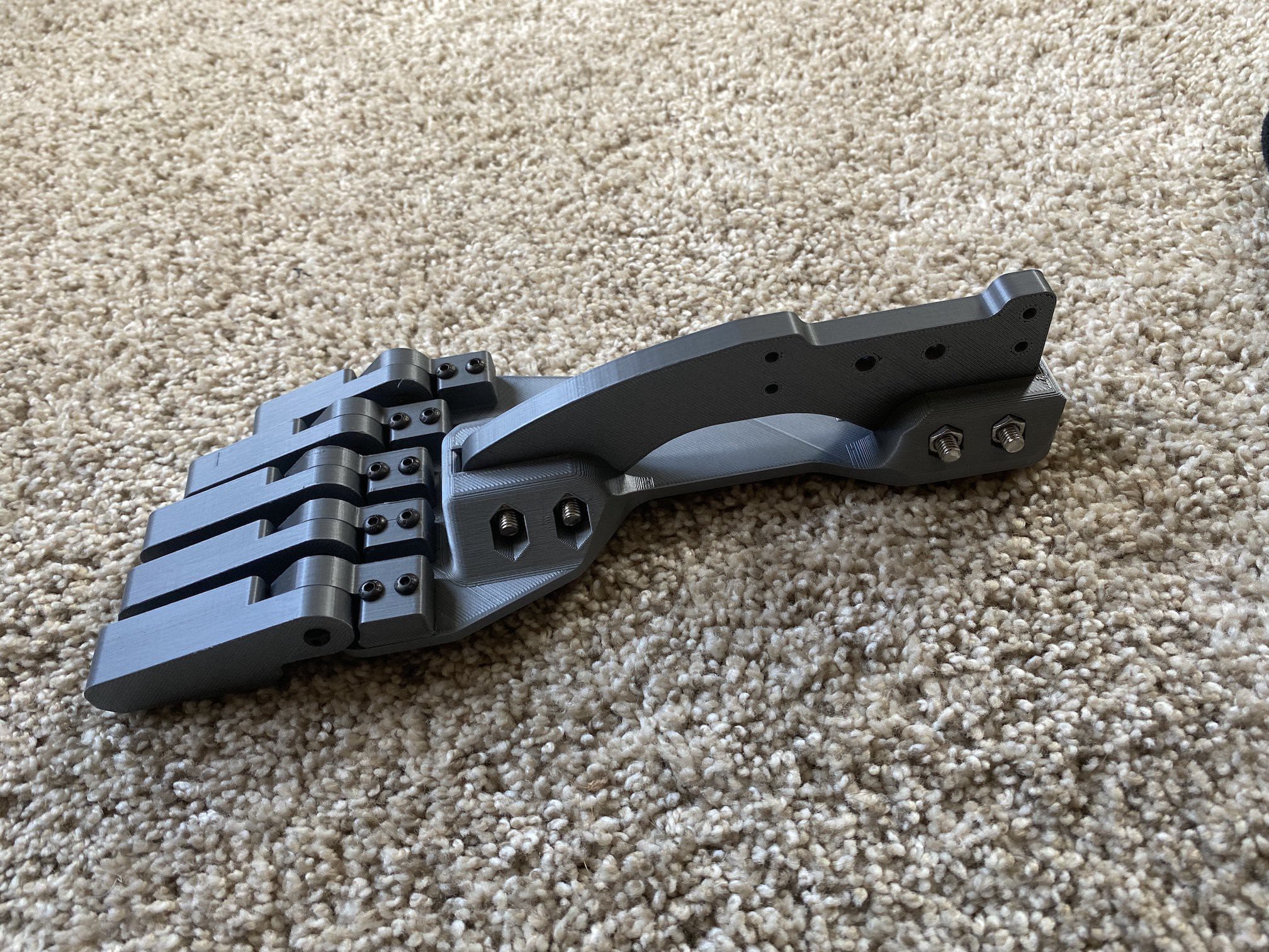
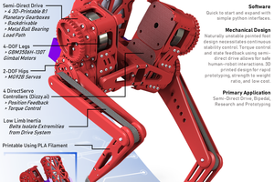
My main goals are to make the mechanical design extremely powerful and agile, so the software has few limitations in control. The design is roughly inspired by the style of the Rev-9 in Terminator Dark Fate, and will be consist of black 3D printed parts, carbon fiber tubing, and milled carbon fiber plates.Actuation systems will be BLDC driven block and tackle pulley configurations with stainless steel 7x7 cable to achieve practically zero backlash, while still remaining very strong and able to handle high torques at each joint. I'll most likely be using ODrive's for all motor controllers, and Infineon's TLE5012B absolute magnetic encoders. My design strategy is to literally start from the ground up, beginning with the legs, and moving upward.
I don't have any bill of materials price yet, but I'm estimating a few thousand USD, and I'll try to keep it as low as feasible while still meeting my primary goals
Components
6×
8318 100kv Brushless Motor
High-torque hobby brushless motors to drive primary joints of the hip, knee, and ankle
2×
5010 360kv Brushless Motor
Smaller, less-powerful hobby brushless motors used for the side-to-side movement of the ankle joint
2×
23x25mm Carbon Fiber Tube
Primary "bone" in the lower leg
12×
10x12mm Carbon Fiber Tube
Secondary supports in the lower leg, and primary supports in the upper leg
16×
TLE5012B
Absolute Encoders for motor control, and directly on each joint to not require any startup procedures
Following my ground-up strategy, the foot was the first place to start designing. At the very beginning I was thinking about designs for the feet, but couldn't quite settle on a look that I liked. I wanted something mechanical, yet still with a good match to the general shape of a human foot... using mine for reference dimensions.
My first thought was some sort of solid core, with faceted panels attached to it. This led to the following:
It was a nice idea, but didn't quite give me what I was looking for, and I had no great ideas for the ankle joint, just some placeholders for a 2dof joint.
I went back to the drawing board and was figuring out the key things I wanted from the foot:
High rigidity to resist bending when lots of force is exerted on the toes
Simple design
Lightweight and compact
Mechanical look
Correct proportions
After reviewing these requirements, I can up with a design where strength and a mechanical look were highly considered:
Based on it actually being printed, you can tell I liked it a lot more!
It had a simple design with a primary base plate reinforced by a vertical fin that would attach to the ankle. The dimensions looked pretty good, and the sprung toes helped add to the realism. The problem with this design was still that I didn't quite know what the ankle would be like, so it was not designed with that in mind, just sort of a modular part I could redesign later (the fin). Another problem was that this was relatively bulky and a little heavier than I hoped for.
After a long time of thought, and jumping around to other joints on the leg, I ended up deciding that cable driven joints would be the best in terms of strength, backlash (basically none), and weight savings. This led me to develop some joints for the knee and ankle using rolling contact surfaces, and block and tackle systems to decrease the tension on the cables, while multiplying the torque output of each joint. Thinking about the actual mechanisms for the joints was a big help to considering how the ankle should connect with the rest of the foot.
This eventually resulted in:
This design is now the one I've settled on as it meets all of my goals very well!
The base of the foot is a 3mm Carbon Fiber plate that provides for the high strength and rigidity I was looking for. Below it, an 8mm layer of EVA foam that will be mounted with M3 bolts and some hex-nuts embedded in printed inserts. A layer of neoprene rubber will be adhered to the bottom of the foot to ensure plenty of grip, and an extra layer of neoprene rubber with cutouts to make a tread pattern will be adhered on the very bottom. This foam-rubber section will be entirely removable so if it becomes damaged or worn down, it will be trivial to manufacture a new one.
Because I designed the primary rolling joint of the ankle first, I was well prepared to add a second axis to the joint (side to side) and easily mount that to the carbon fiber plate. Additionally, there are 2 forward arches that help add extra stiffness to the carbon fiber plate when large forces are exerted on the very end of the toes. It's not visible here, but the outline of the carbon/foam/rubber does not actually include the larger slots as shown on the top toe part. This helps to make the entire foot more rigid, while not sacrificing the added realism of the more defined toes.
This design looks very mechanical, but also extremely close to realistic dimensions. The EVA foam and rubber layers also acts as a shock absorbing material that give the foot more volume and utility.
Manufacturing
So far I have milled the EVA foam layer, and am very happy with the shape. Additionally I have printed most of the ankle parts, and they look very nice when all put together!
(This is my Sphinx 55 from OpenBuilds)
There are 19 pockets for the embedded nut inserts that will let me bolt the foam/rubber section to the carbon plate on the foot....
In my previous post I mentioned the work-energy theorem, but I made a slight mistake when using it in the calculations... That states that the total work done by all forces acting on a body is equal to the change in kinetic energy, but of course that also includes gravity, and I forgot to add that into the calculation at the end to show the average power figure.
Now I use the work-energy theorem to find the work done by the motors counteracting gravity to push the center of mass upward, and also the instantaneous power at each step of the simulation.
The following graph shows the power generated by the motors at each point in time during the jump in the previous video. Peak power is about 2800W, and the average is 1411W...
The following video demonstrates a simulated vertical jump of the robot in a custom Python program I wrote. Center of mass is displayed by the black and yellow circle at mid-torso level, and the sizes are all exactly as planned.
Ignore the big block actuators shown on the leg... they were from an old design that will not be in the final leg... I'll update the simulator program later on.
A little bit of info on the simulation:
All joint info is calculated by a function which only takes the desired "charge" distance... 0m would be right at the peak of the jump when the leg is fully extended, and -0.70m is the charge amount when the robot is fully compressed. This function is likely to change later on to find the most optimal path/config for force production.
Input parameters are the following during the calculations at each step:
force_scale: one leg is simulated, but the robot has 2 legs, so I can multiply the final output force by the one leg and simulate having both legs.
motor_kv: rpm/v of the motors
battery_voltage: voltage of the battery or power supply
max_current: max current in amps to apply to all motors in the leg
max_joint_torque: limits on joint output torque in Nm
The torque on the hip, knee, and ankle are all calculated based on motor_kv, battery_voltage, max_current, and the angular velocity of the joint to acount for the motor's torque/speed curve.
I'm using a linear torque speed curve where the motor can output 100% torque at 0rpm, and 0% torque at the no-load rpm.
Motor reduction ratios are as follows:
Hip: Constant 1:15 ratio
Knee: Rolling joint that varies according to:
This produces a non-linear reduction ratio ranging from 1:11.3 at the ends of the knee's travel, and 1:16 when the upper and lower legs are 90° apart. Theta is the internal pulley angles, and is offset 90°, so the knee ranges from -90 to +90 rather than 0 to -180.
Ankle: Rolling joint that varies according to:
This produces a non-linear reduction ratio ranging from 1:12.7 at the ends of the ankle's travel (+/-60°), and 1:18 when the ankle is at neutral position.
Once all joint torque's are calculated, the torques are transformed to normal force on the ground based on the current position. My joint info function produces results where the center of mass and ball of the foot are always at x=0, so using the following equation is all that is necessary to calculate normal force produced by each joint.
However, because all of these forces are likely to be different, I just take the minimum, and use that as the applied force on the ground.
In the end, the robot will determine motor torques to apply for a given ground reaction force, but this seemed like a good way to simulate the force production for given torques without having any more advanced joint angle functions where all joints produce the correct torques to stay on the desired path while also pushing off the ground with a desired force.
Because all of my actuators are cable-driven, I also calculate the tension acting on each cable system, and a safety factor so I can make sure I don't go outside any limits and snap cables that are too weak. (I decided on 1mm 7x7 stainless steel cable that has a supposed breaking strength of 140lbs or 622N, but I'll try to keep a safety factor of at least 2)
Taking into account the force pushing down on the robot, and the normal force on the ground, the net force is applied to the robot using simple Newtonian physics with F = ma. Each step then just applies the acceleration to the velocity, and integrates position according to velocity and acceleration during the time step (0.001s).
At the moment the robot disconnects from the ground, the current velocity is projected to find the expected jump height where the current kinetic energy must match the gravitational potential energy at the peak of the jump. The calculation to determine height (m) from velocity (m/s) ends up being: