Close
0%
0%

[HEX]POD - Climate Tracker & Digital Nose

A versatile sensor platform with expansion and customisation capabilities [dev]

Public Chat
Similar projects worth following

[HEX]POD

by eBender
⚠️ This project is in development.
Iterative design process.

GitHub
Instagram

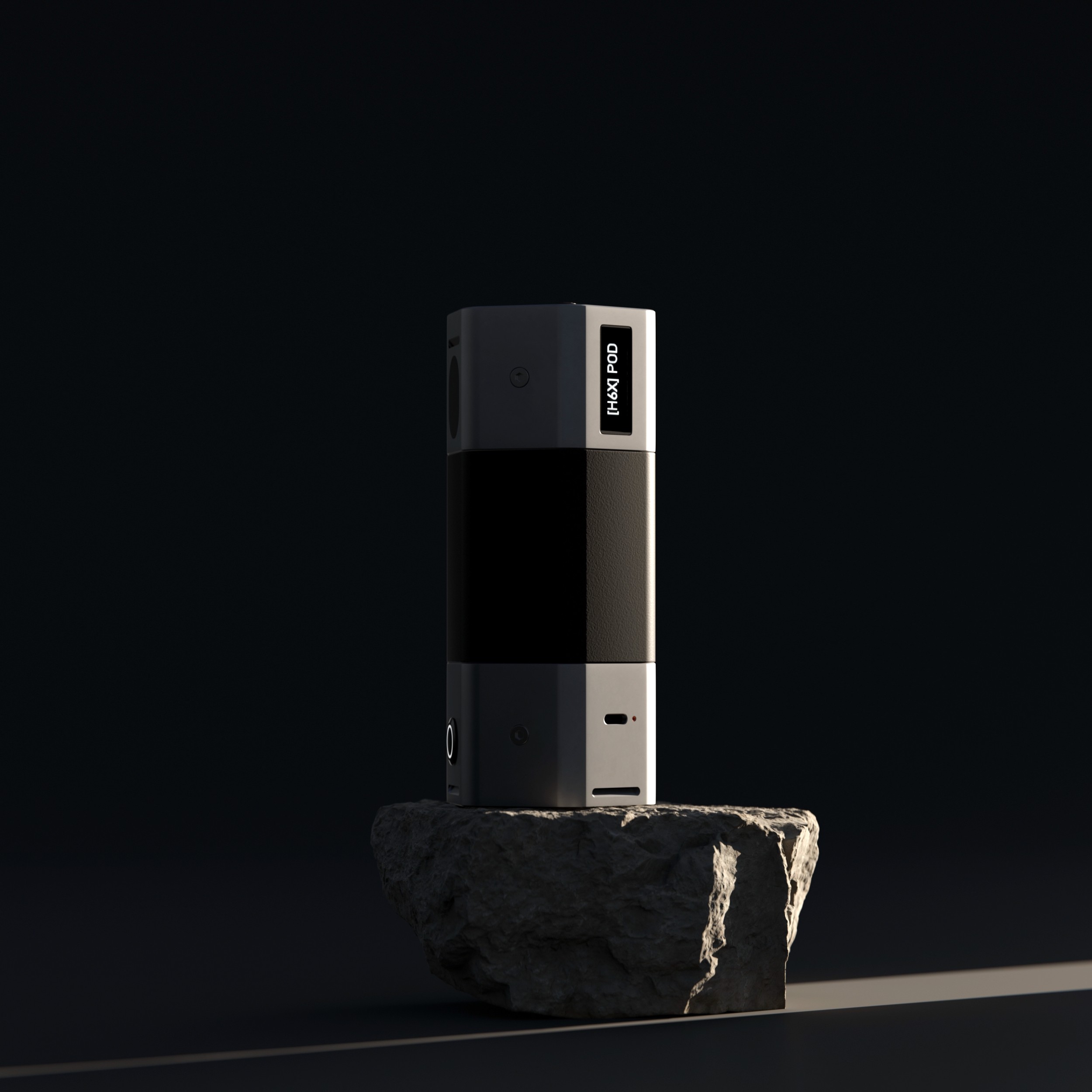
The [HEX]POD is a portable, multi-purpose, intelligent, environmental, multi-sensor development platform with focus on being a 'Digital Nose' with relatively cheap components, using Sensor fusion and Neural Networks to discern different chemicals and smells in the air.

Goal:

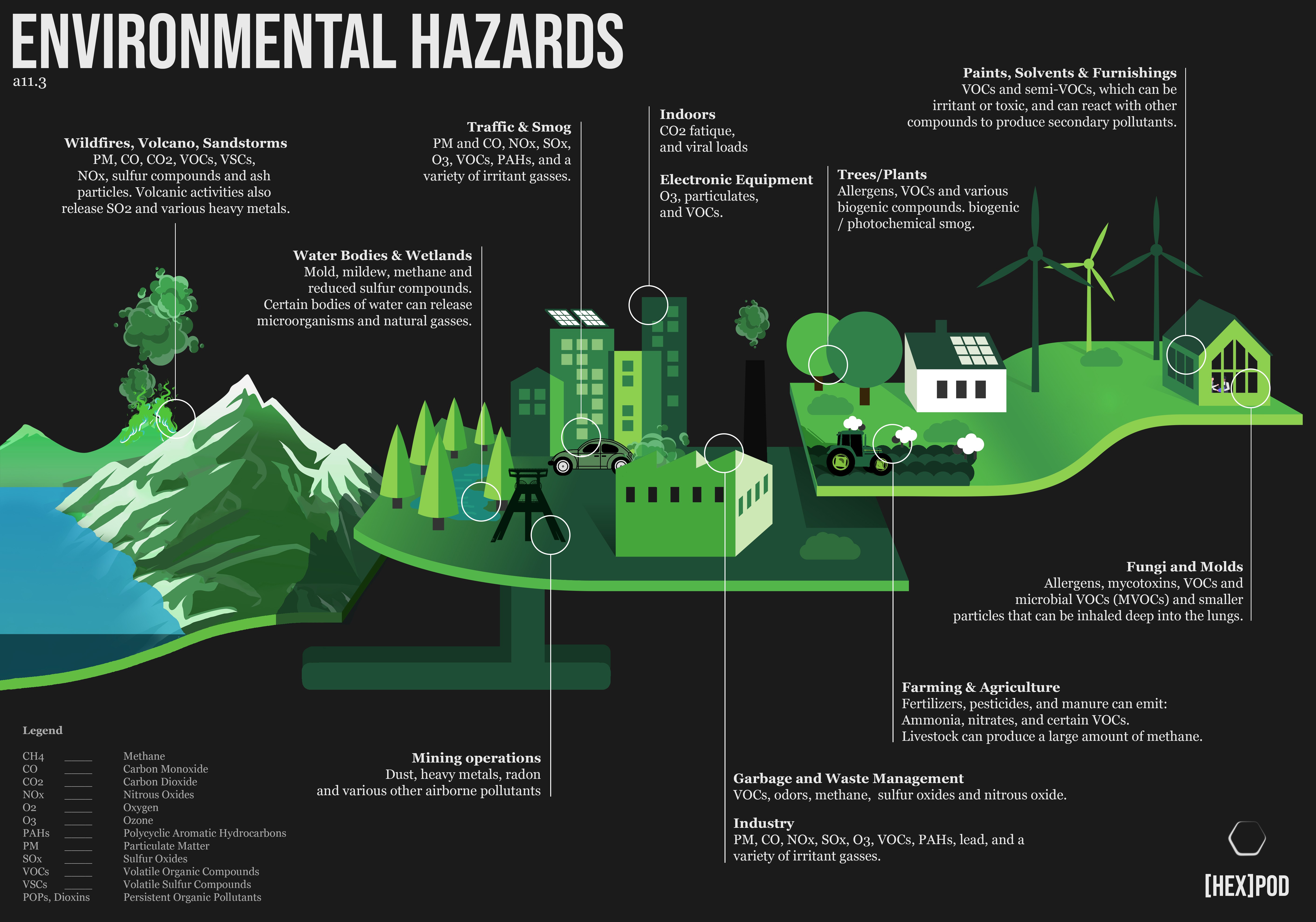
Technology has advanced significantly, with sensors being ubiquitous in our devices and gathering a wealth of data. One thing we had to learn from Covid, there is a critical aspect of our quality of life that remains relatively neglected in the public sector:

The air we breathe.

The goal is to empower people by raising awareness about airborne hazards, from aiding those with chronic respiratory conditions to detecting spoiled milk. While the concept of a 'Digital Nose' has been explored before, [HEX]POD is positioned as a user-friendly solution that seamlessly integrates cutting-edge technology into a compact and portable platform.


DevKit version

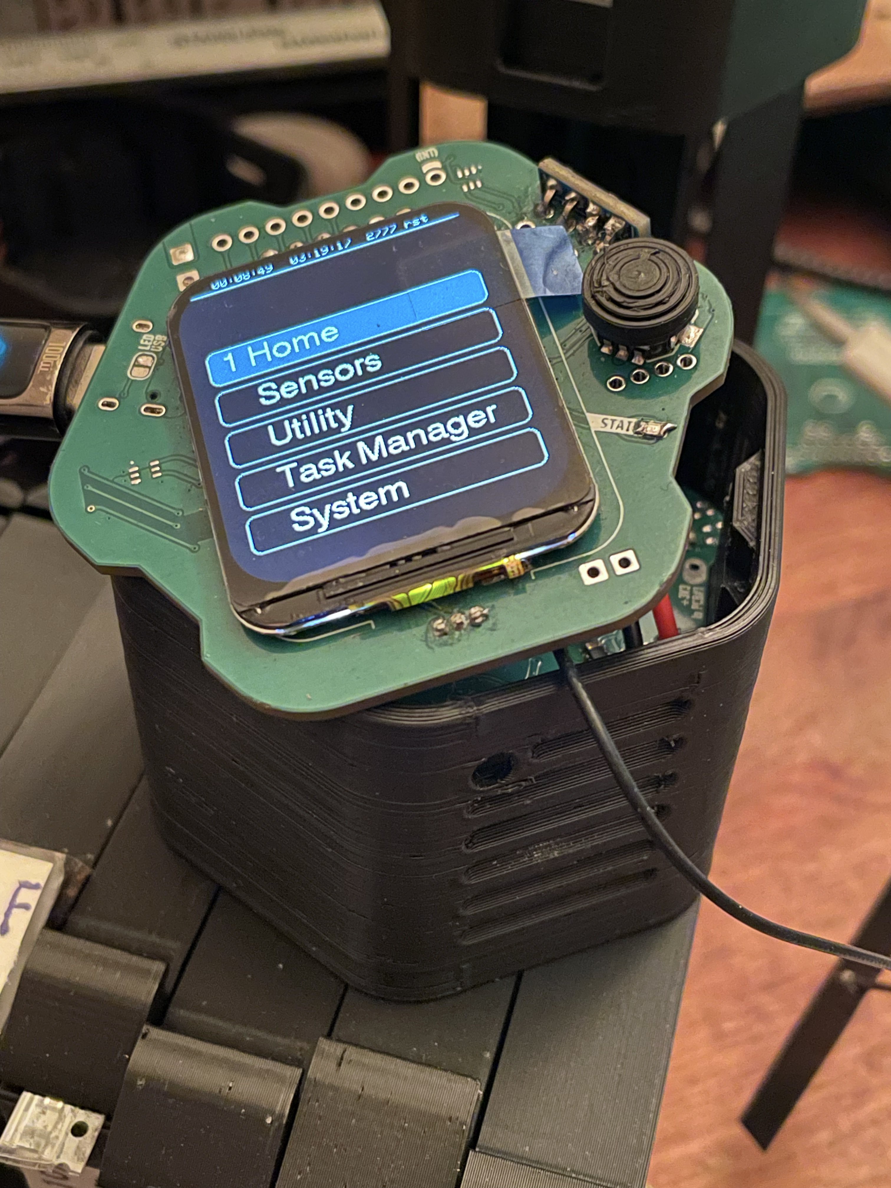
I scaled down the original plan to the essential features to be able to move ahead faster with development. I call it the DevKit. For now, the DevKit version houses 4 Air quality sensors, 2 screens, a battery, a blower fan and 16 I/O pins to hook up other modules and things and much more. It is a versatile platform to play with Sensor Fusion, ML, NN and any other externally connected modules.
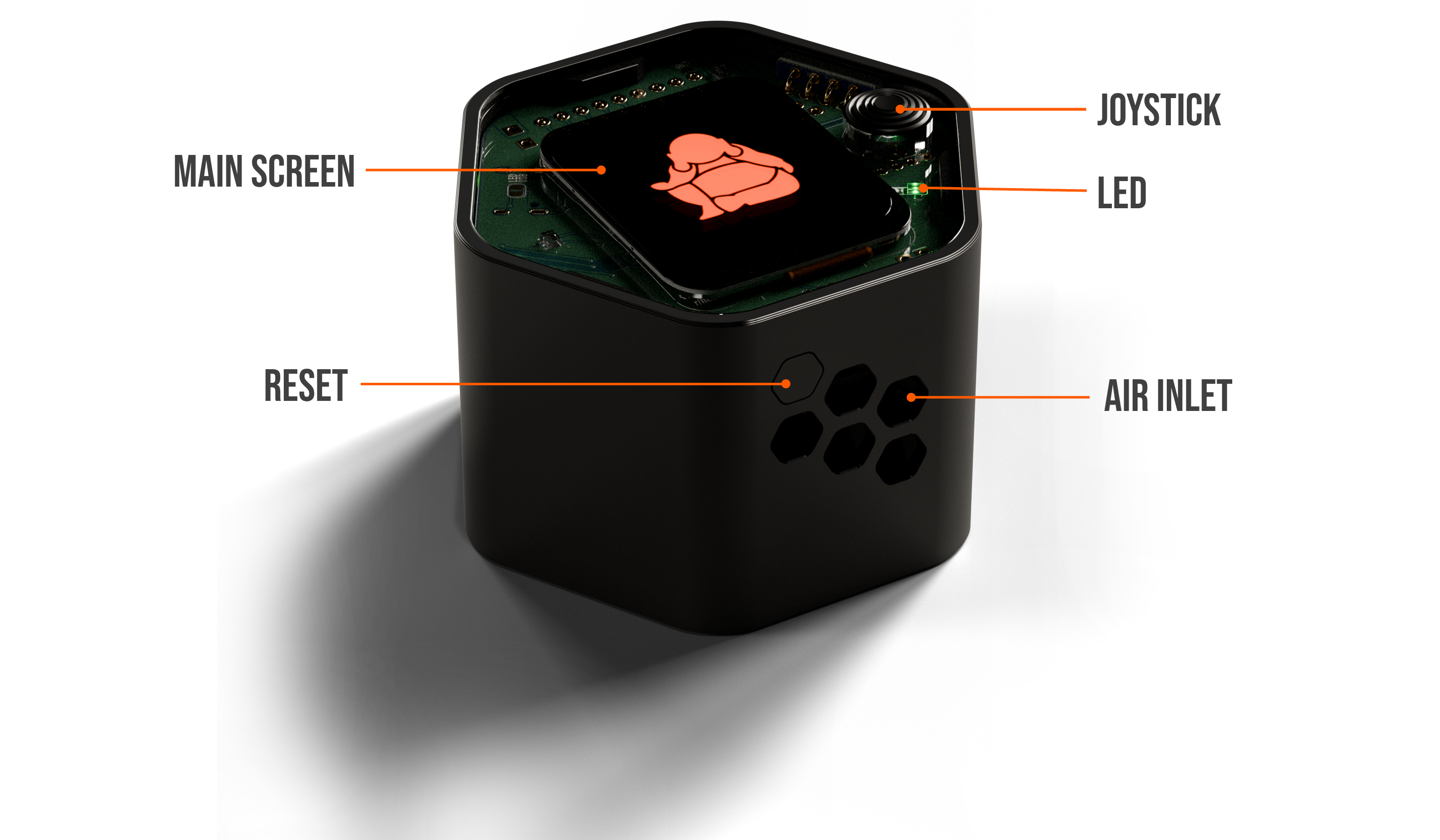
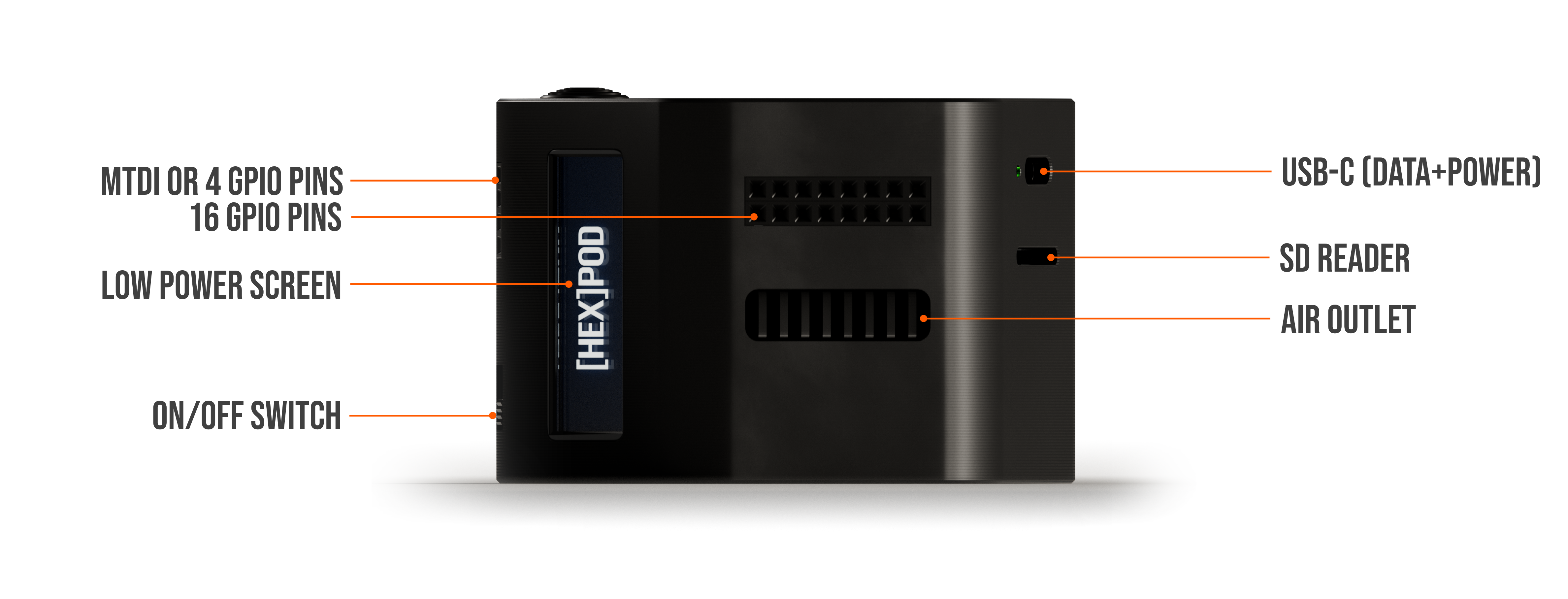
Dev Kit version [wip]

DETAILS Function Module
SENSORS Air Quality
Smells & Gases
Light Meter
Motion Sensor
Temp Sensors
SCD41, SGP41 (CO2,  VOC, NOx)
BME688 (x2) (Gas, T, H, P + AI Gases)
LTR-308 (Ambient Light)
LIS3DH (x2) (MPU, 6-axis)
DS18B20 (x5)
POWER 15W Charging
Battery Life: tba
2000mAh, 7.4Wh (103450 Battery)
tba
SCREENS TFT IPS 1.69"
OLED 0.91"
Main 240x280px
Low power always-on
IO 4-way Joystick and 2 Buttons
SD Card Reader
16 I/O Pins
Web Interface


8 from Multiplexer, 8 from ESP32-S3

working on custom, versatile local server
Misc 5V Blower Fan
Quiet Air Duct
1,5CFM, -25dbA, 8500RMP
Eval. work in progress

Current Sensors

BME688: Wide range of trained gases, Temperature, Humidity, Pressure
SCD41: CO2 (Carbon Dioxide), Temperature, Humidity
SGP41: VOC (Volatile Organic Compounds), NOx (Nitrous Oxides)

Potential future sensors and detections

PASCO2: CO2
ENS161: Various AQIs
Smart NanoTubes: (cutting edge sensor)
- Carbon Monoxide (CO)
- Oxygen (O2)
- Ozone (O3)
- VSCs (Volatile Sulfuric Compounds)
- Ethanol, Benzine, Alcohol
- Formaldehyde (CH2O)
- Ammonia (NH3)
- UV


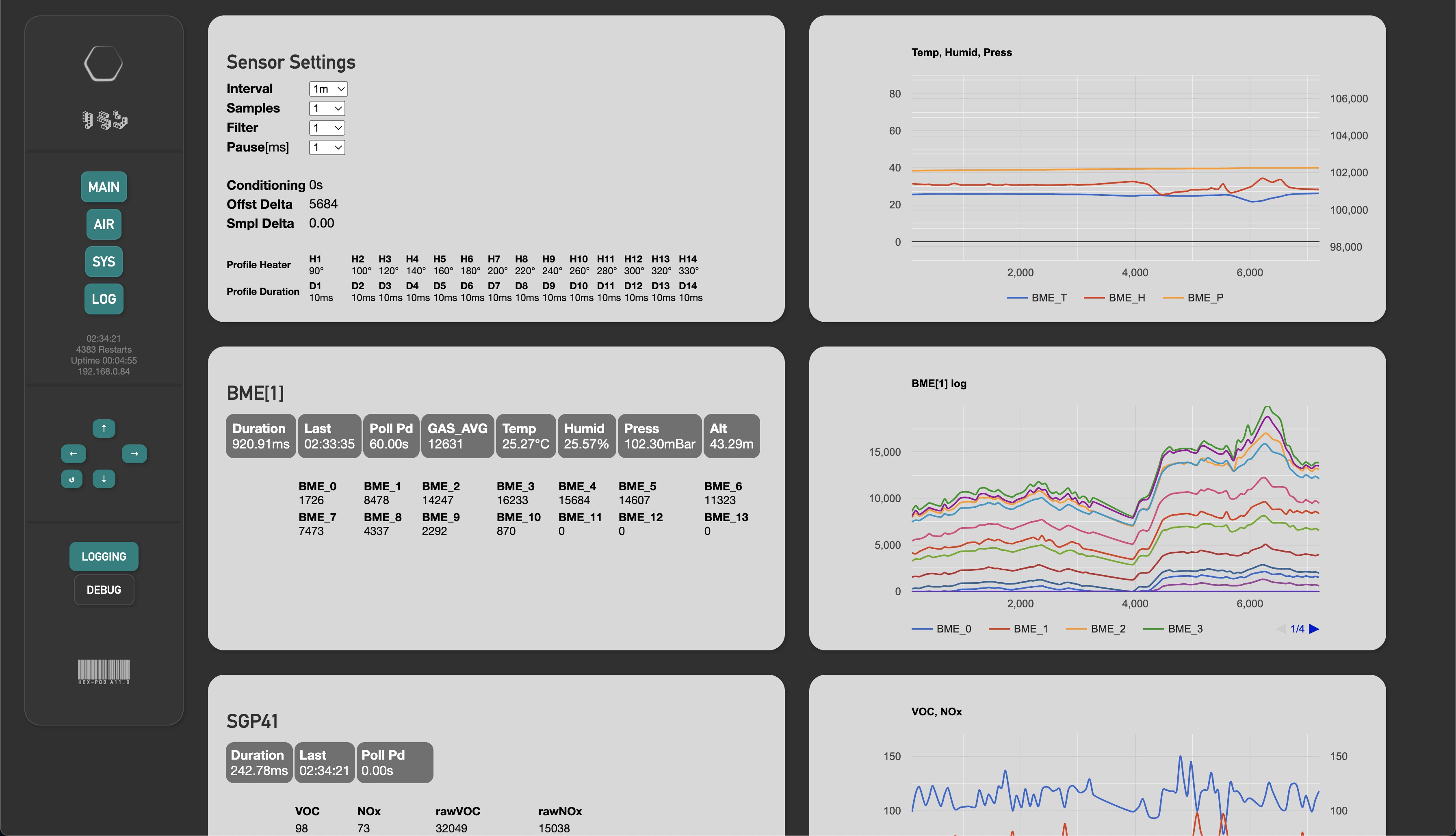
Local Web Interface [wip]

AIR Page


Where it came from

In 2019 i went to India where i travelled on Foot, Train and ultimately Motorbike from Kolkata to Kerala back up to Dharamshala and everywhere in between. So across the whole country twice.

Around March 2020 I was spending my time with friends in Rishikesh, one of whom slowly got really sick, right when COVID really started in India...

Read more »

  • First steps with TF and Python + Data collection

    eBender03/12/2024 at 03:38 0 comments

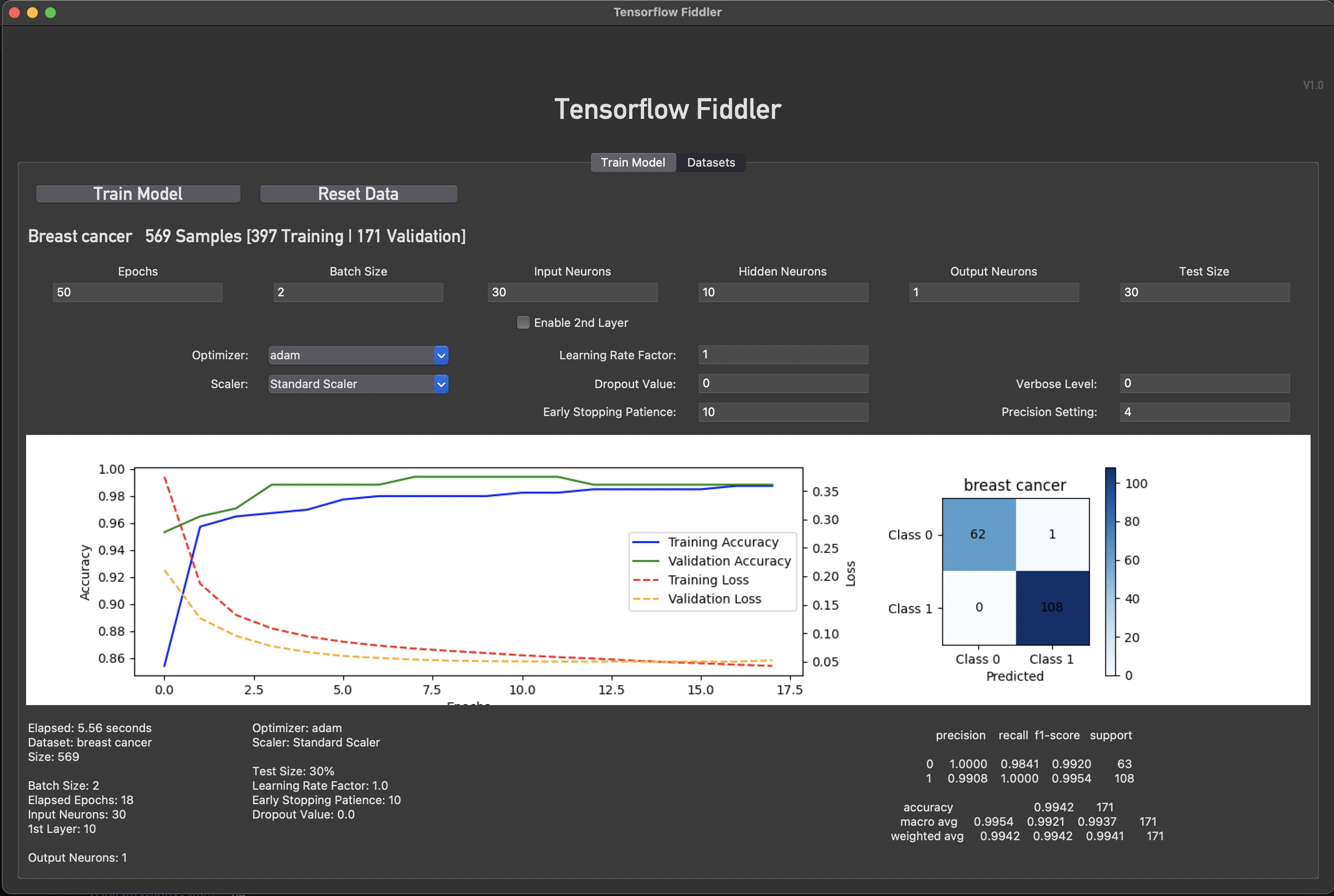
    I programmed a first version of my own Tensorflow 'Fiddler'. For now it uses provided datasets.
    The goal was to get familiar with parameters, scalers, optimizers and training procedures.

    This is the first app that i programmed ever. In a language that i have never written in before (python). 
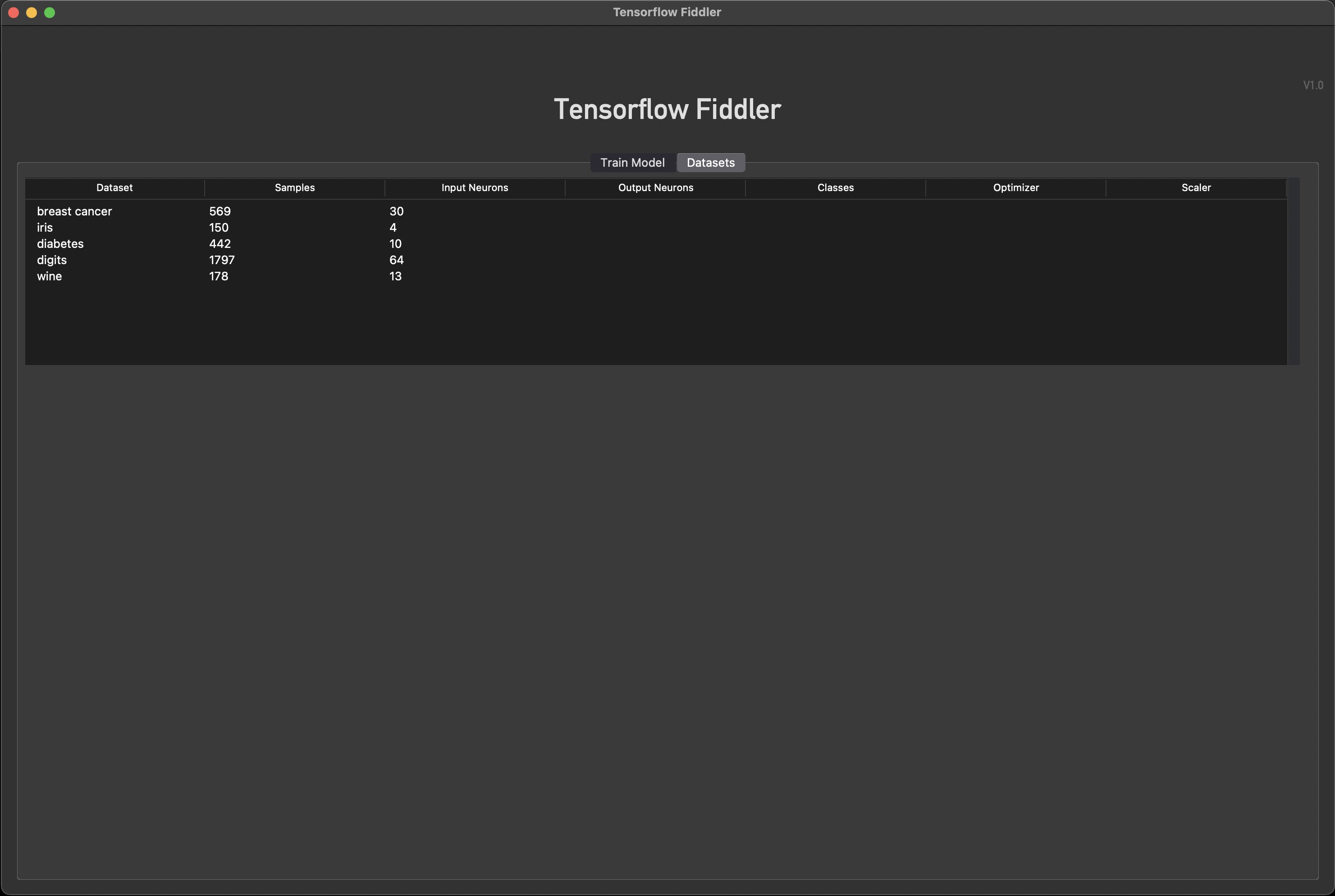
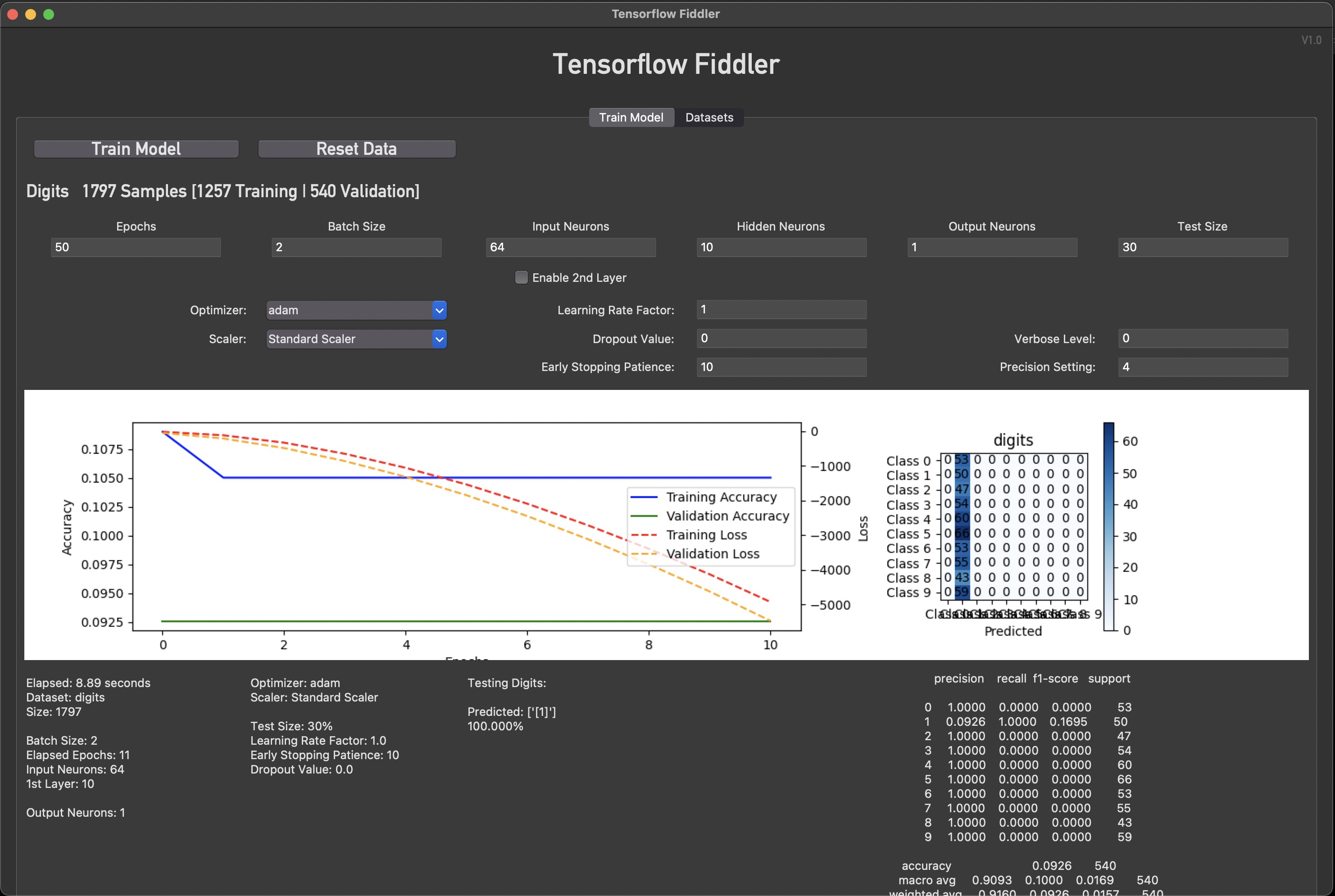
    As can be seen in the next pic, i am running into my own knowledge cutoff when the dataset has different numbers of output Neurons or a way to display the result correctly. The app does adjust automatically for Input neurons and one extra hidden Neuron Layer can be activated. As well as all things that can be adjusted are 'broken out'. Still, more fiddling + research needed here.

    It gets real weird with the 'digits' dataset obviously since my Fiddler is not set up to handle this kind of output. Or does it? The output displays a '1'. Also a way to properly test a trained model is missing. Right now the model tests itself with one datapoint after it has finished training on top of the automatic eval.


    The point of all this is to make a hub that can be used to train my own models with gathered Air Quality Data from the [HEX]POD and then pass on the model to the [HEX]POD for testing detection accuracy. 

    Do i move on from the existing datasets and start making this app about my own datasets or do i make it handle all the eventualities? To learn more about how all this works the latter would make sense, then build a completely new version of the app optimized for my own use case.

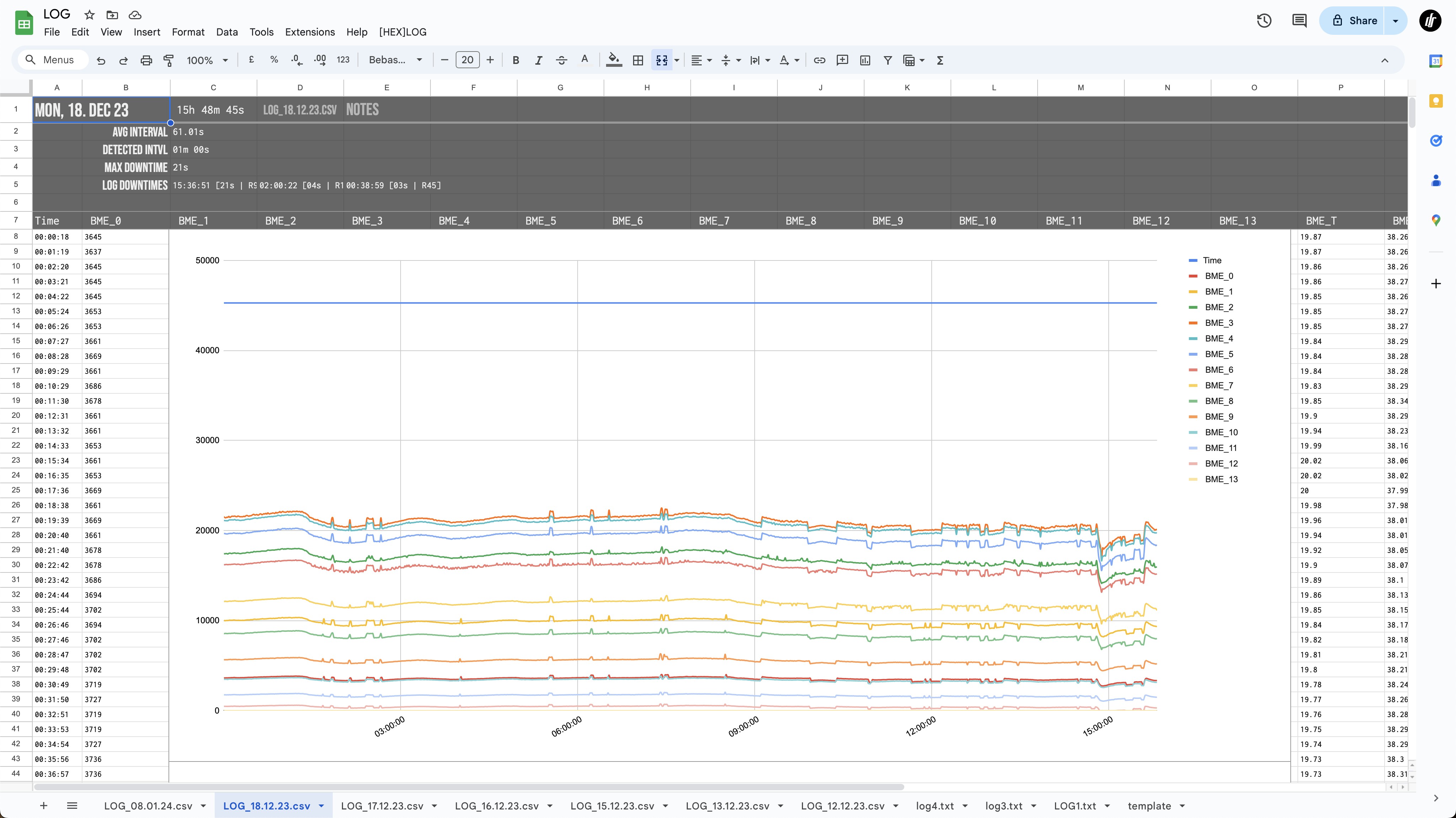
    Collecting Sensor Data - Auto-Logs on Google Sheets:

    I also programmed an automatic system that imports data logs from the [HEX]POD, detects the interval, and any downtime or missed samples and more. It is automatic for now. I could also embed this meta data into the log, but this seems more robust since it adjusts itself for any eventualities and automatically detects errors during sampling.

    To burn in the sensors and get a first idea about collected data, i have run multiple test sessions of 3h - 21h duration. SGP41 and SCD41 - CO2, VOCs, NOx, and multiple redundant Humidity, Temp, Pressure datapoints are also part of the Log.

    An option to add Notes during the sampling process, to mark location or environmental changes can be set via the Web Interface only for now. 

    An overhaul of the OS and Interface running on the [HEX]POD is in order.
    I also want to assemble another updated hardware version that utilizes both BME688 sensors plus MPU and Ambient Light data.

    BME688 profiles:

    For now i am only running one incrementally stepping heater / Timing profile on one out of two BME688s. This does not yield any meaningful 'smell' data. A more complex sequence of profiles needs to be implemented. This can be found in the BoschAI app, they provide some good documentation. These profiles need to be chosen carefully, as different sequences of length and temperature respond to different compounds / 'smells'.


    Sampling environment:

    Another thought i had: I need to build a clean test-environment (maybe a ventilated box with carbon and hepa filters) to reset the Air sensors and provide a baseline for any smells. This would also help with training datasets on only one specific smell, without interference from the environment.

    Any pointers are welcome!

  • [HEX] State of the build #7

    eBender12/02/2023 at 02:34 0 comments

    [HEX]POD a11.3 updates!

    Finally! after a long pause due to job things i am back at the [HEX]POD!

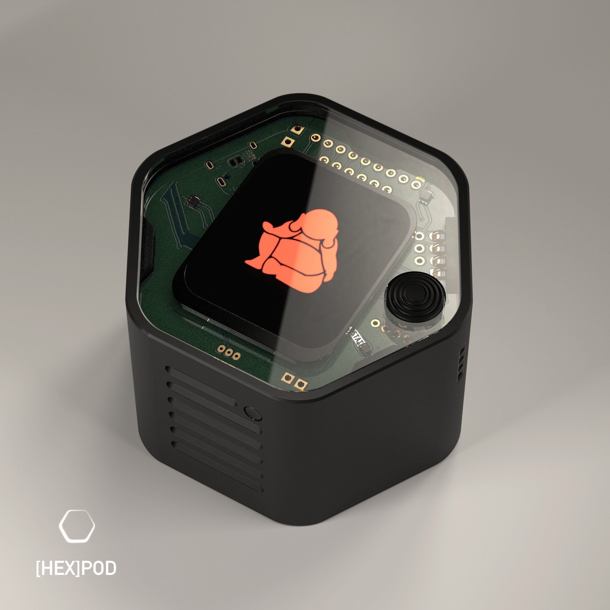
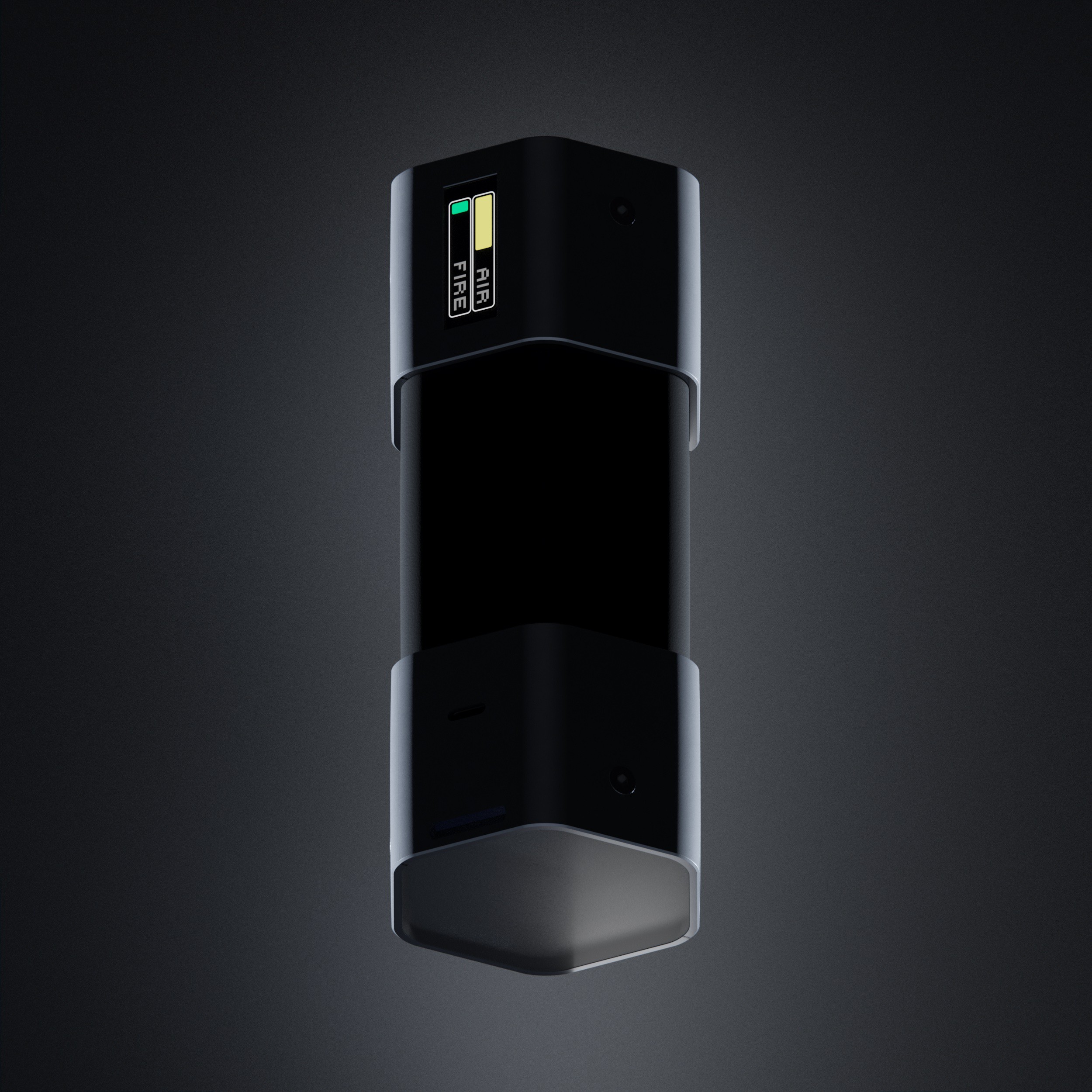
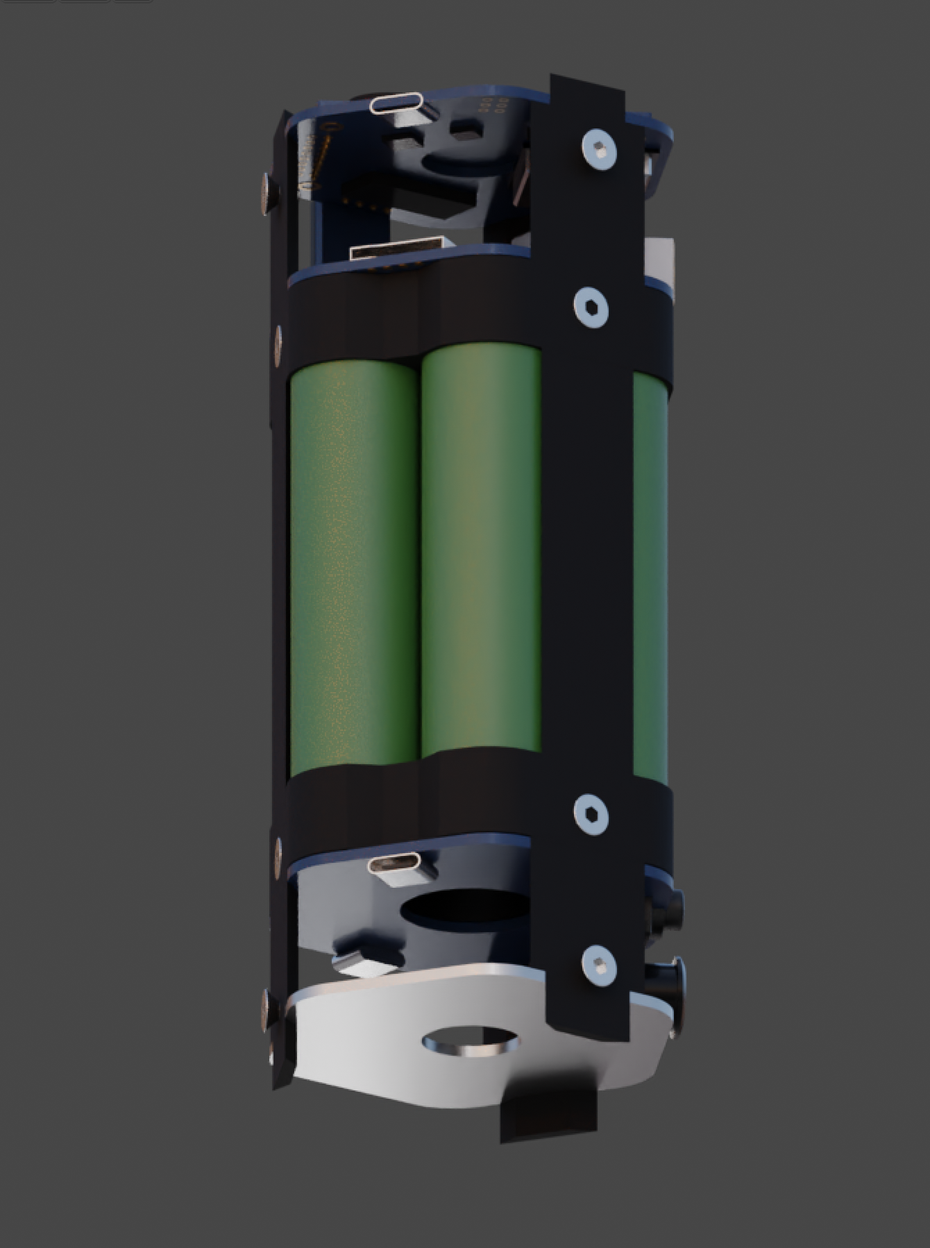
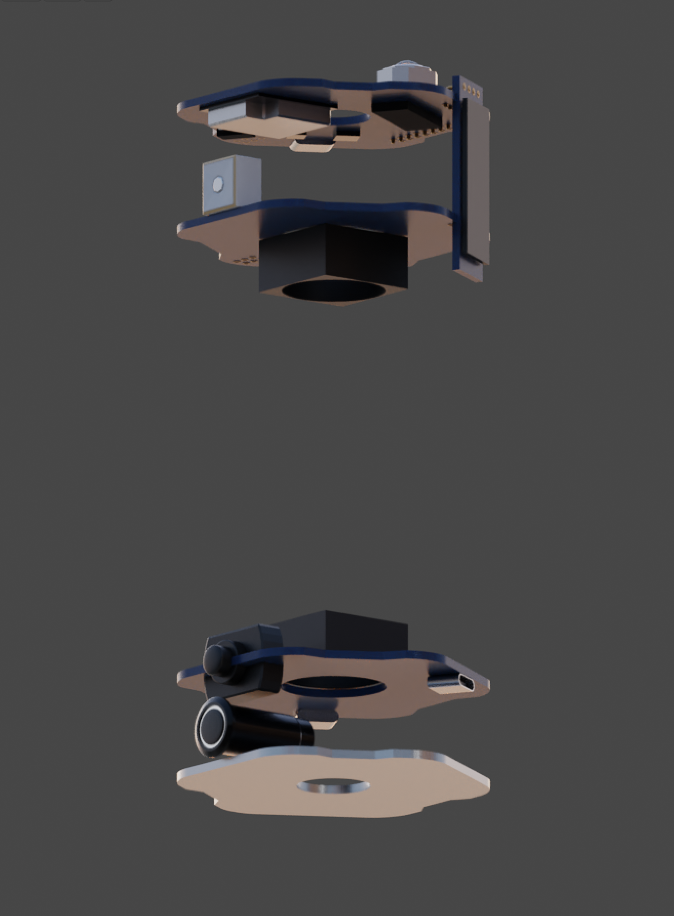
    Biggest update is the temporary change to a reduced form factor, a MVP (minimum viable product).
    I chopped off the lower 2/3rds and fit everything into the top portion of the earlier designs. 

    Other updates:

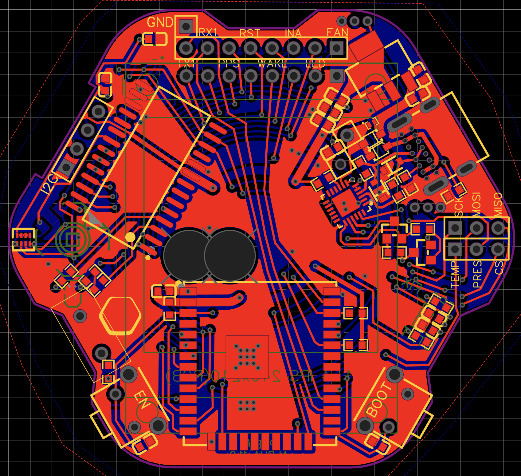
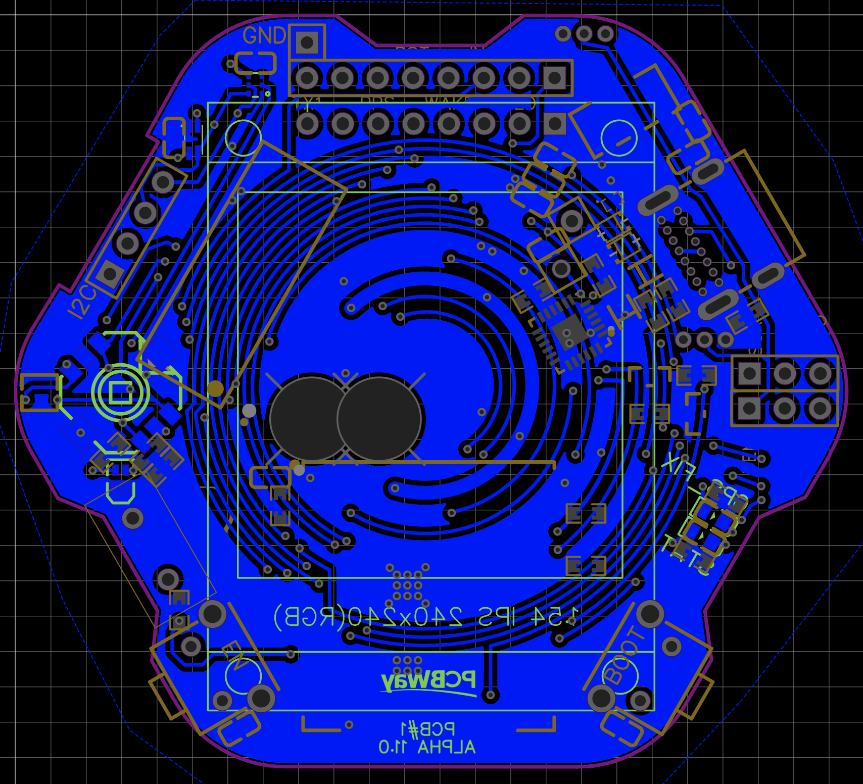
    • new PCB#1 fully working (small bugs)
    • first PCB#2 almost fully working
    • core functions up and running
    • Dev interface programmed
    • Web interface programmed

    I made some great progress which i will share over the next weeks.
    Here is a sneak peek at whats coming:

    more soon, thanks for reading!

    Manu

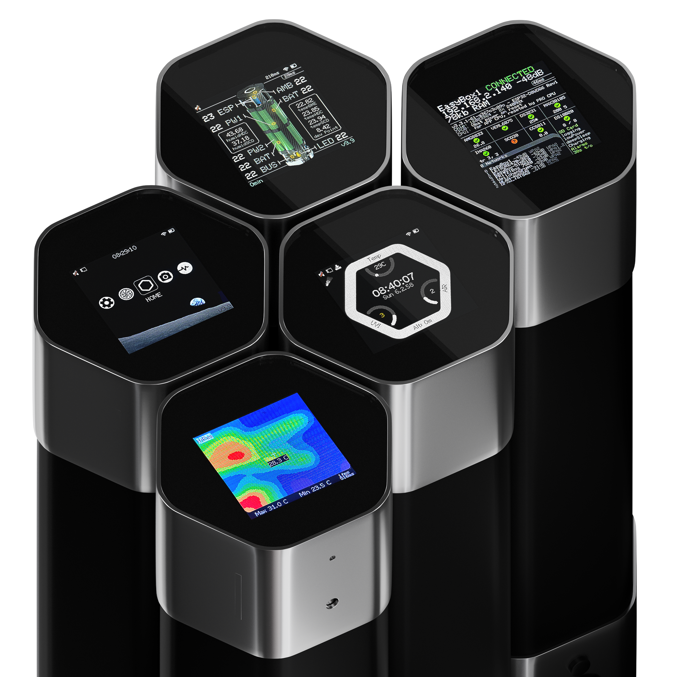
  • Concept Renders

    eBender04/20/2023 at 08:11 0 comments

    And a quick update, it's been a while again.

    - I overhauled PCB#1 another couple of times and am about to order it now.
    - Updated components for longer lifespan, availability and overall structuring.
    - Optimized for low current draw in low power mode.
    - worked a lot on production structure and planning, part organizing, data structuring, brainstorming and 

    something exciting coming soon!


    Read more »

  • [H6X] State of the build #6

    eBender12/10/2022 at 09:03 0 comments

    Alpha 11.0 to 11.2 - PCB Updates

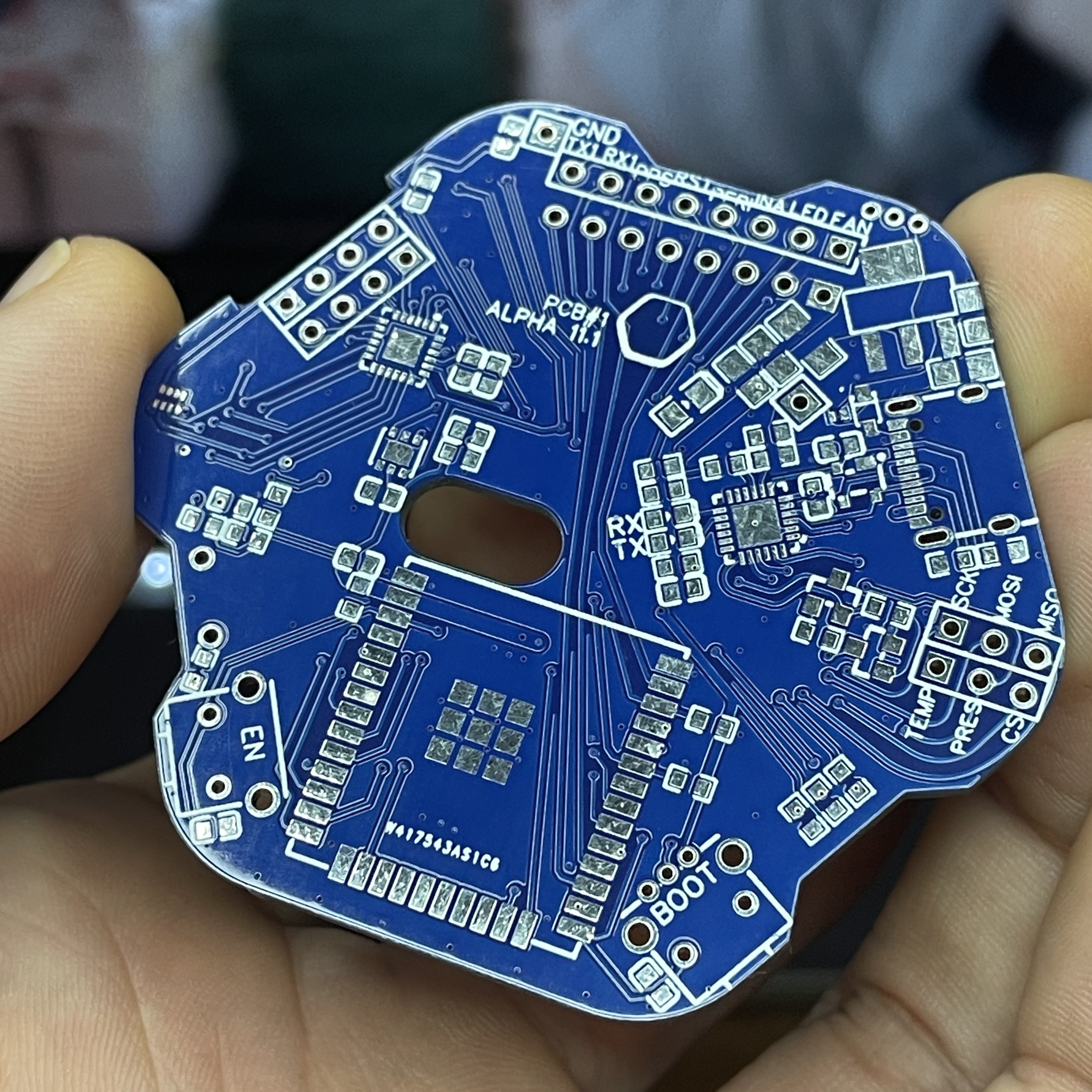
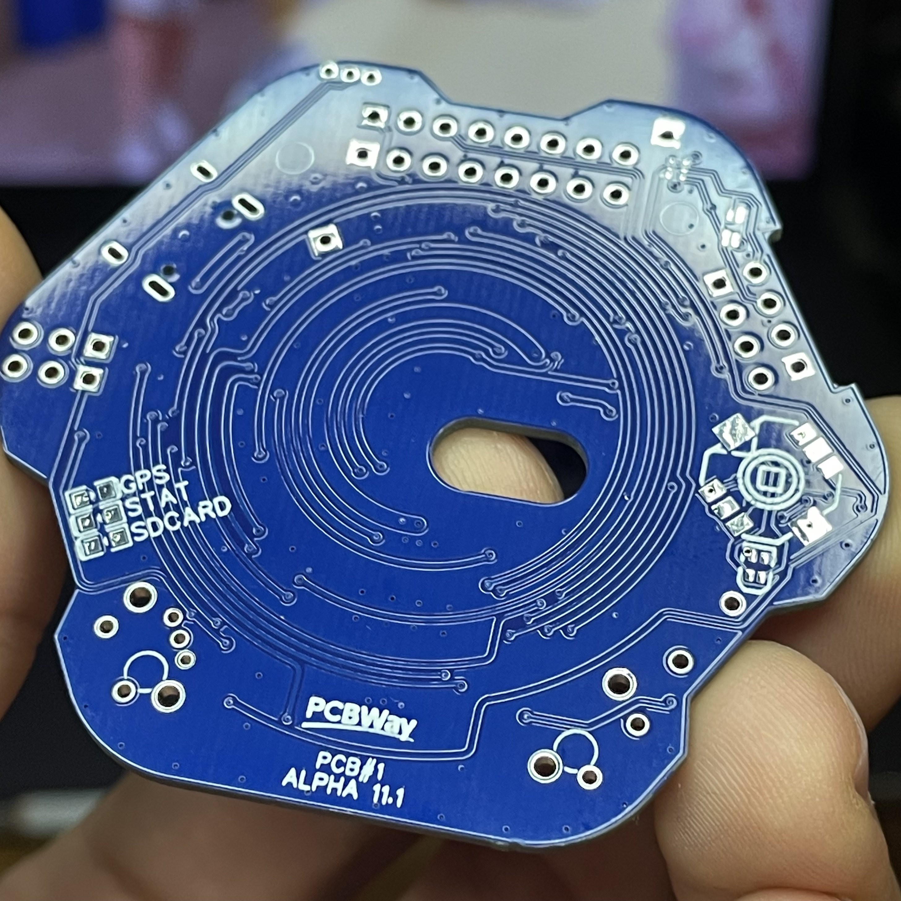
    An update on my first testing with PCB design from version a11.0 to a11.1.
    First of all PCBway did a beautiful job manufacturing the PCBs! All errors and bugs are from my inexperienced design. Thanks to them for the support! 

    What worked:

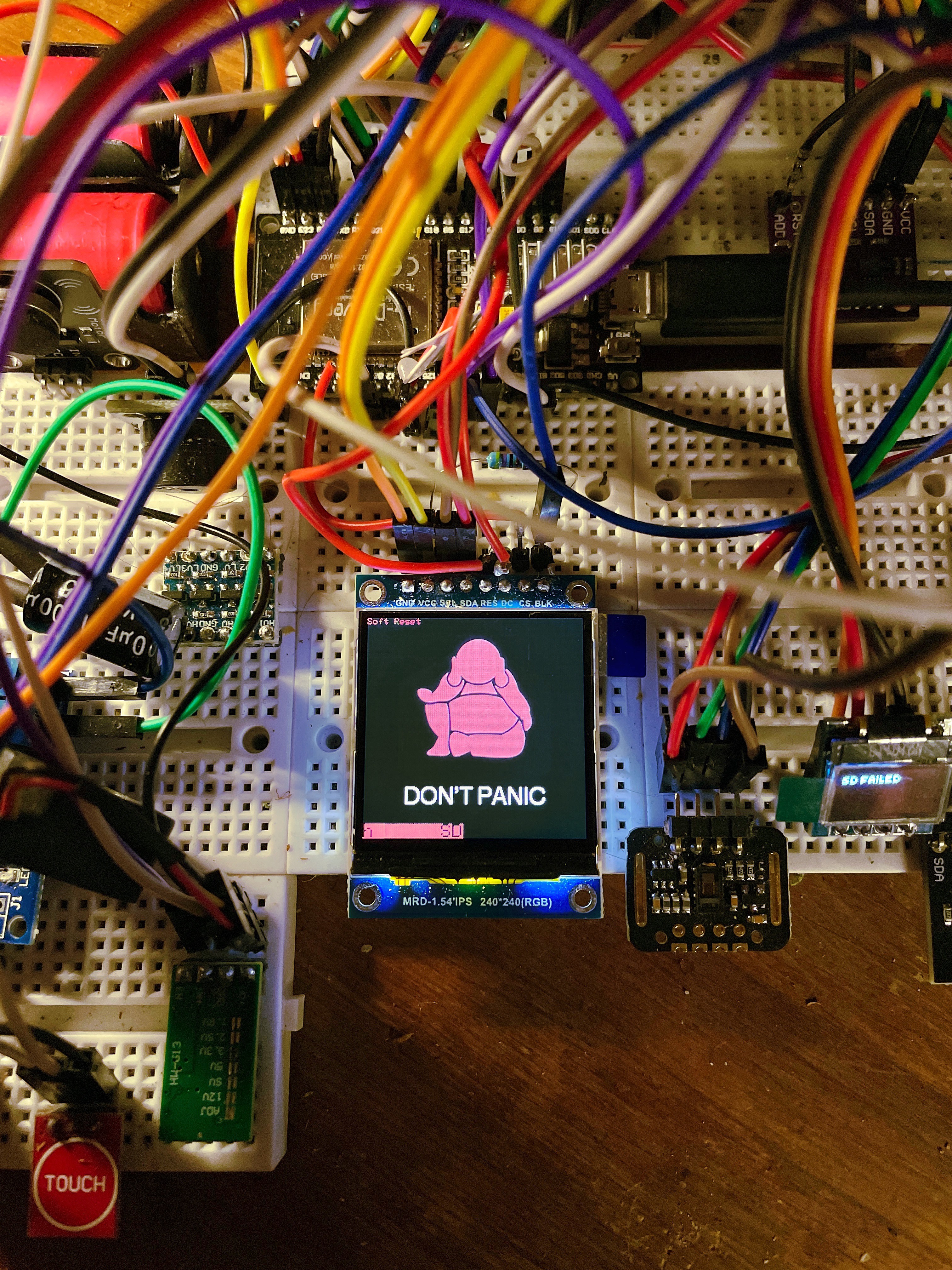
    • ESP32
    • 240x240px LCD Screen
    • USB-UART Bridge programming (only with reduced speed)
    • LEDs
    • Enable-, Boot Buttons, Auto-Reset 
    • UV Sensors

    What i did wrong: 

    • the selected multiplexer PCF8575 only runs on 5v, but still worked on 3v3 as a LED sink
    • I2C bus was throwing errors at all speeds, probably trace interference
    • Serial upload threw errors sometimes, probably trace interference
    • selected wrong pins on ESP32 and TFT, had to bridge 2 to make it work

    Assembly of the previous version 11.0, which you can see here. It had an unfixable error with the USB-UART Bridge and non-available multiplexer, so i went on to the next one. (always double-check the schematics!)

    Alpha 11.1 Working:

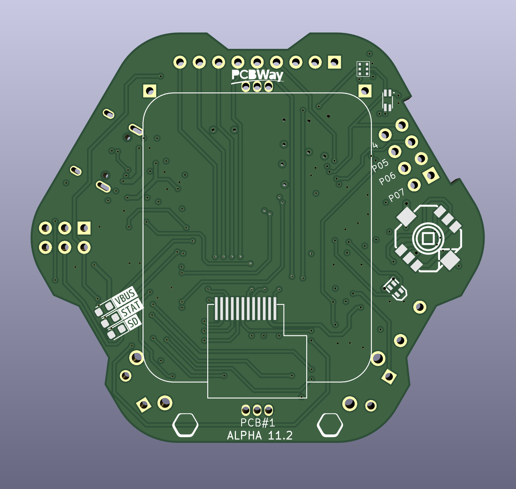
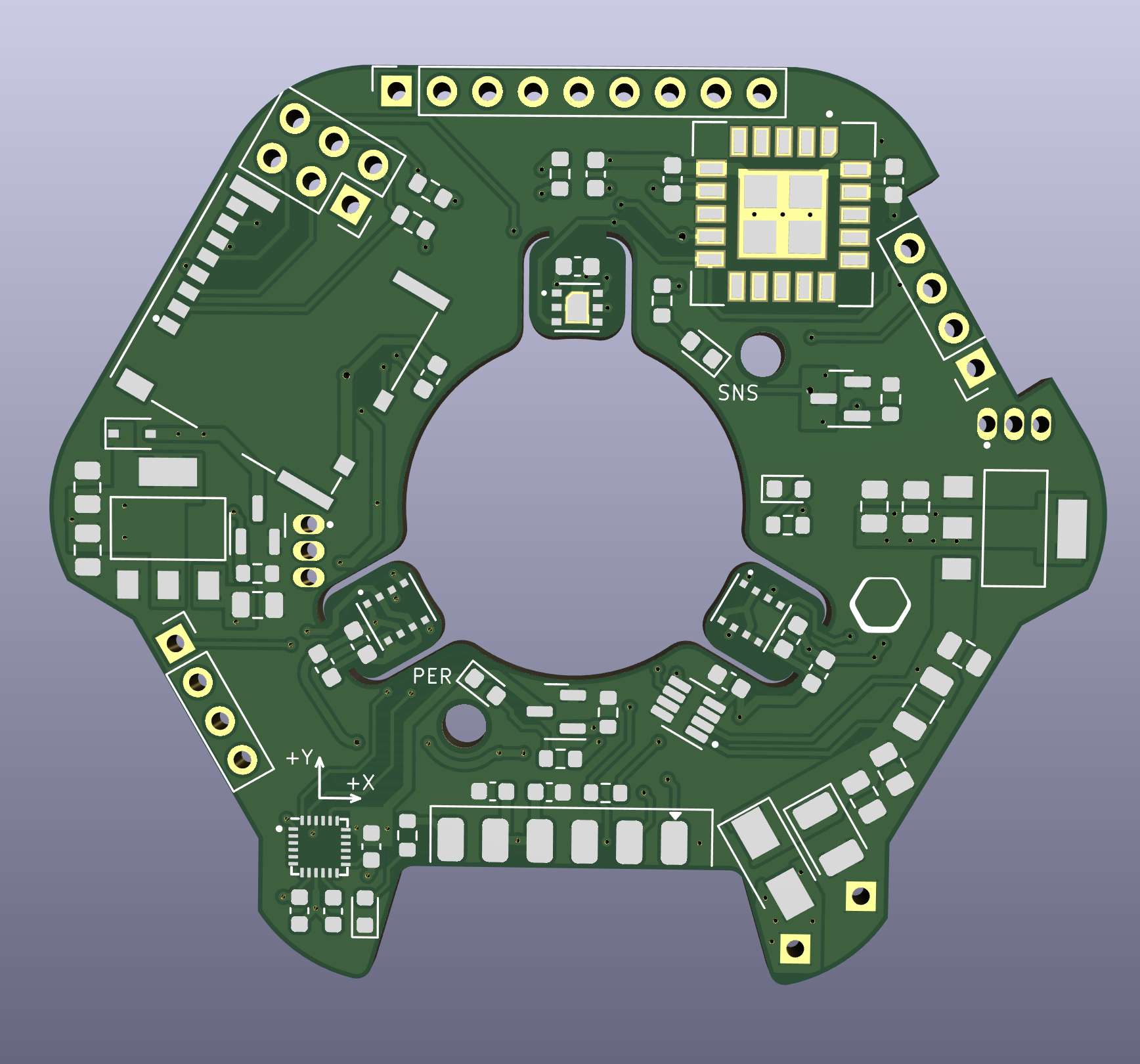
    PCB#1 - Alpha 11.1 Front

    Back (manufactured by PCBway)

    Next up...

    a fully redesigned Alpha 11.2 and testable working prototype

    I got some help to do an overhaul of the entire pcb designs, to make sure they are properly designed and so i don't have to keep reiterating too many times. The power and lamp side with PCB#3 + 4 will have to wait for now.

    Design is already done and to be sent out to PCBway for manufacturing. Again, great gratitude to them for sponsoring, couldn't do it without them!

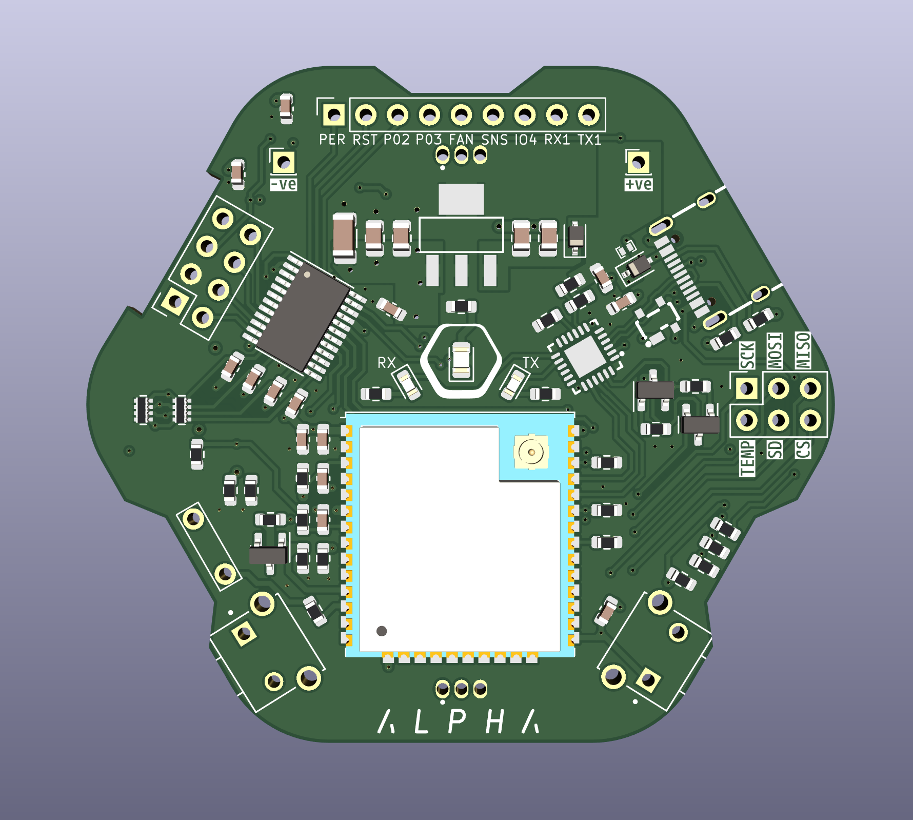
    Alpha 11.2 Changes to PCB 1 + 2:

    • path / power path improvement
    • change PCB#1 to 4-layer design
    • switched PCF8575 to PCA9535PW
    • switched screen from 240x240px LCD to rounded bare240x280px LCD
    • all remaining IO broken out
    • switched GPS to M86-M33
    • added dedicated power off control to sensors and peripherals for extreme power saving

    PCB#1 - Alpha 11.2 Front

    Back


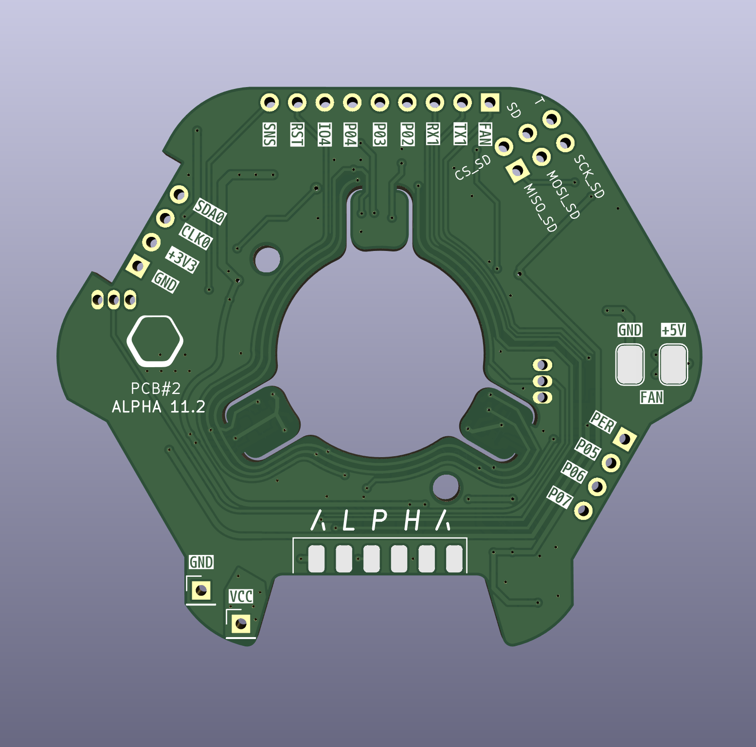
    PCB#2 - Alpha 11.2 Front

    Back

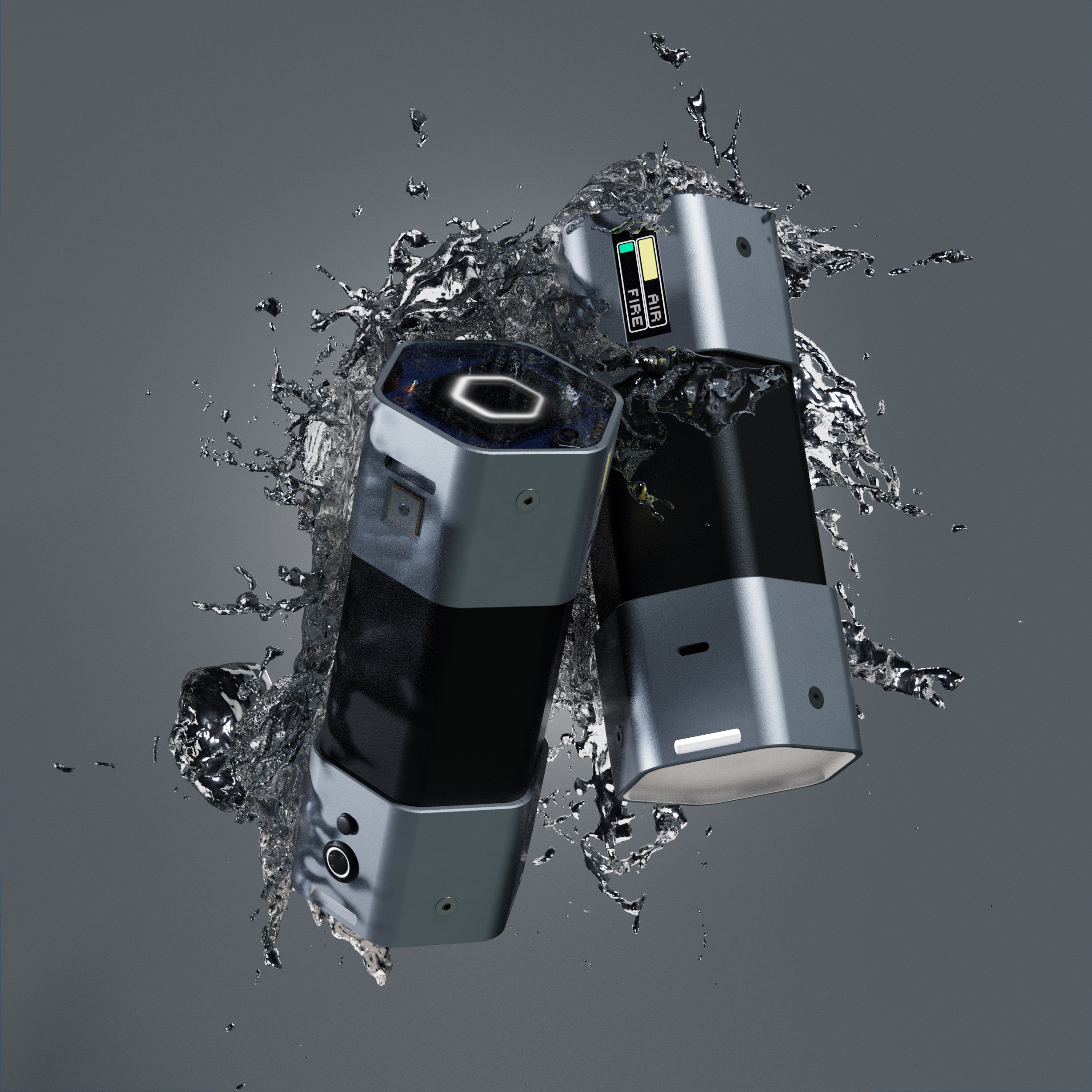
  • Render dump.

    eBender06/30/2022 at 13:00 0 comments

    Eye candy time!


    Quick update: 

    finished the design of PCB#1 (post coming soon) and sent it out to PCBway who were super fast and great! 

    It's been 3 weeks now, DHL decided to send the package on a little world tour (Shenzhen>Germany>Moldova>Romania>Italy>Germany) and now it seems to be stuck. But no biggie, i'm in Spain right now anyways, just hope i can persuade them to send it to me eventually. -.-


    more Renders after the fold:
    Read more »

  • [H6X] State of the build #5

    eBender01/10/2022 at 04:04 0 comments

    alpha 11.0

    New design Sketches for custom PCBs:


    New PCB sketch

    PCB prototyping, 3D printing, new designs.

    I hit power path and size limitations with my breadboard prototype spider for while...
    and then i was offered sponsoring by PCBway. love when things come together by themselves.

    So, i already started the PCB design and tests of the 3D printed enclosure.
    I scaled down the prototype a little bit. Basically temporarily taking out half
    of the battery, 1 sensor and the Spotlight LED. Makes it a much sleeker device
    and prototyping slightly easier. I can scale up again after the first successful PCBs.
    Gotta keep in mind that i want to keep it somewhat modular, space for expansion and user accessible.

    Change-log [a10.2 -> alpha 11.0]

    • temporary Size cut-down
    • switch to custom PCBs by PCBway
    • switch to 3D printing from Aluminium bracket design for now
    • switch to 4-way Joystick clickable with 2-Color LED
    • switch to BME688 T, H, P, AI Gas
    • switch to APDS-9250 RGB, ALS, IR Sensor
    • added MCU23017 I/O expander
    • added P82B715 I²C signal booster (if needed)
    • added MPU9250 back in (used to have I²C conflict)
    • removed VEML7700, BME390

    PCB#1 Design

    PCB#1 - ESP32, Multiplexer, Screens, User I/O, USB-C UART

    PCB#2 - Sensors, GPS, SD card reader

    PCB#3 - Power supply, BMS, USB-C controllers plugs, temp sensors

    PCB#4 - LED matrix diffuse, PWM Led controllers, temp sensors, Thermal Camera?

    thanks PCBway for sponsoring, excited to see the first one!

    Read more »

  • [H6X] UI Video Update

    eBender07/12/2021 at 12:19 0 comments

    Progress:  66,9%      Hardware: v9       Code: a10.0

    quick video of almost the whole OS.

    * Time and Heart Rate BPM is not working correctly right now.

  • [H6X] UI Update

    eBender05/24/2021 at 03:57 2 comments

    Progress:  66,9%      Hardware: v9       Code: v9.9

    I've been working on the UI and made some progress i want to share.

    Mainly Home and Menu Screens and some minor updates.
    I realised i haven't featured the Air Quality/indirect virus detection theory
    functionality yet, that will be getting its own post soonish.

    These are actual screenshots of the display (or photos rather, haven't figured out the eSPI screenshot readRect() code yet). Some pages are still cluttered and older, and i have yet to implement smooth fonts, but it's at a good state to show and explain.
    Read more »

  • [H6X] State of the build #4

    eBender04/28/2021 at 23:27 0 comments

    Progress:  65,6%      Hardware: v9       Code: v9.8

    Change-log

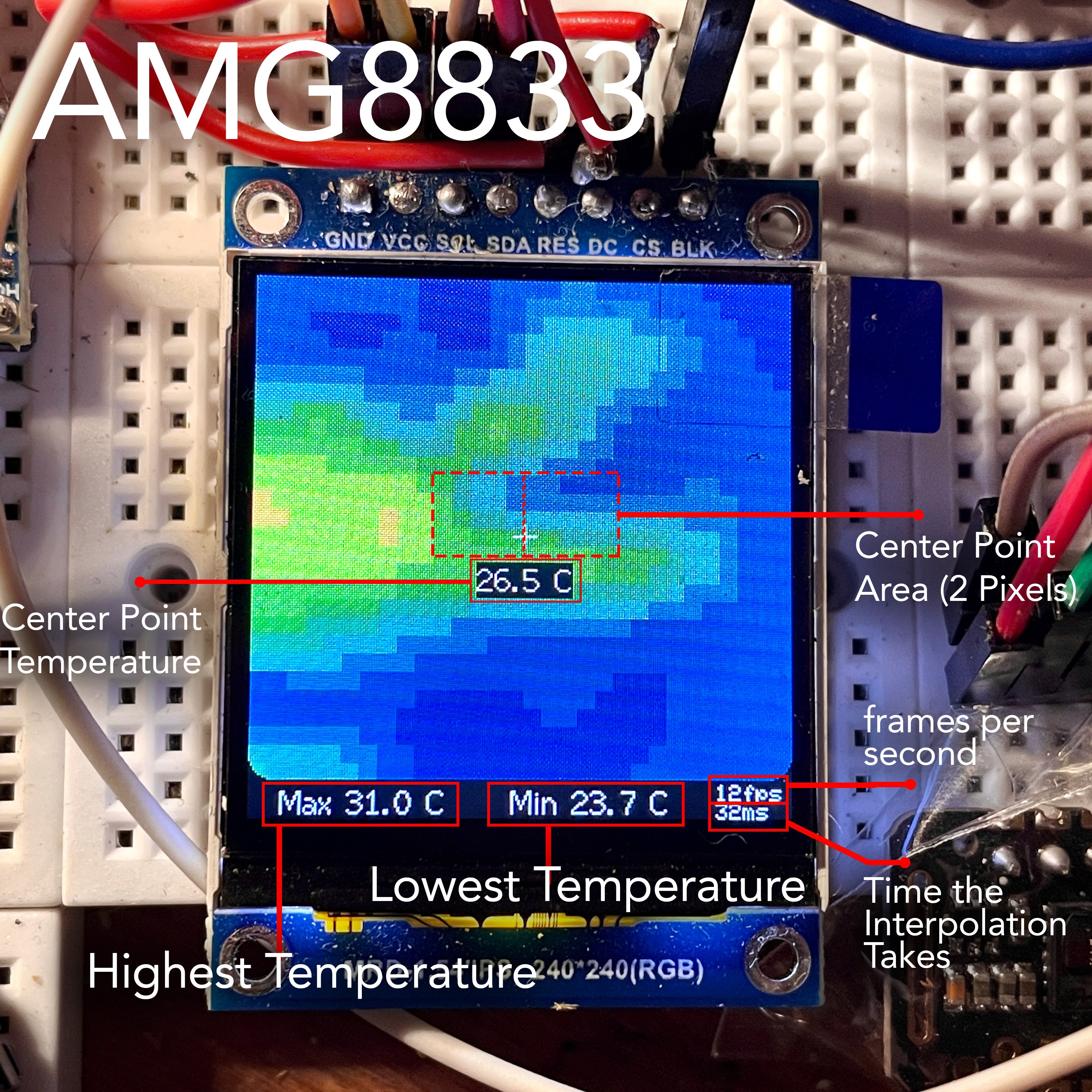
    • implemented AMG8833 8x8px Thermal Cam
    • added Button2 library for Interrupt double-click detection
    • enabled INA260 Interrupt low voltage alarm to trigger system power off through Buck converter EN pin
    • removed pull-up resistors on all I2C sensors, keeping 10k main I2C pull-ups
    • bug fixes

    Issues:

    • detecting SD unmount or error inside Loop() not working anymore
    • removed MPU9250 for AMG8833 to work (I2C addresses)


    AMG8833 Functions:

    Using Algorithm from the Adafruit AMG88xx Library.

    Screen shows:    Center Point Value, Max Value, Min Value, fps,  Interpolation Time

    • LowRes Mode      30x28 Pixels Interpolated, 12 fps 
    • HighRes Mode     120x111 pixels Interpolated, 1 fps (+Auto-Exposure)
    • Full Screen burst mode    collects the highest value out of the full array
    • Center Point burst mode  collects the highest value out of the 2 center pixels

    Button Single-Click:    Trigger Burst Measurement (small 0.49" screen shows 3-sec countdown)
    Button Double-Click:  Toggle Measurement Area (Center Point, Full Screen)

    In HighRes mode i maxed out the Resolution so the frame Rate drops to 1. The Colour Temperatures are mapped to onscreen Min and Max Temps. Kinda works like a simple exposure compensation in a normal camera. The adjusted values get passed on to the LowRes mode if switched. Default temperature scale is 22C - 33C.

    It features a Burst Mode (Averaging Mode) to get a more accurate reading with the 8 bit sensor values, by averaging 50 samples over 3 seconds. Measurement will always be taken from the highest temperature seen by the Sensors inside the selected Measurement Area (Full Screen (64px) or Center Point (2px)).

    Issue: i can't, for the life of me, figure out how to access the full color spectrum to have smooth color transitions. I tried using the eSPI colors and a conversion method, but could only get it to work by accident with smooth colors going from dark blue to purple, and dropping 6 fps. no good. Could have something to do with the 16bit color mapping and how they are arranged in the array, since the actual 8x8 sensor values are 8-Bit, but the array only holds about 32 or 64 colors it looks like. i don't understand how to map the array correctly, or where to get a premade one.


    more after the jump:
    Read more »

  • [H6X] State of the build #3

    eBender04/23/2021 at 17:18 0 comments

    Progress:  64,8%      Hardware: v9       Code: v9.8

    Update: Time for some pictures of Hardware implementation and UI progress:

    Prototype v9
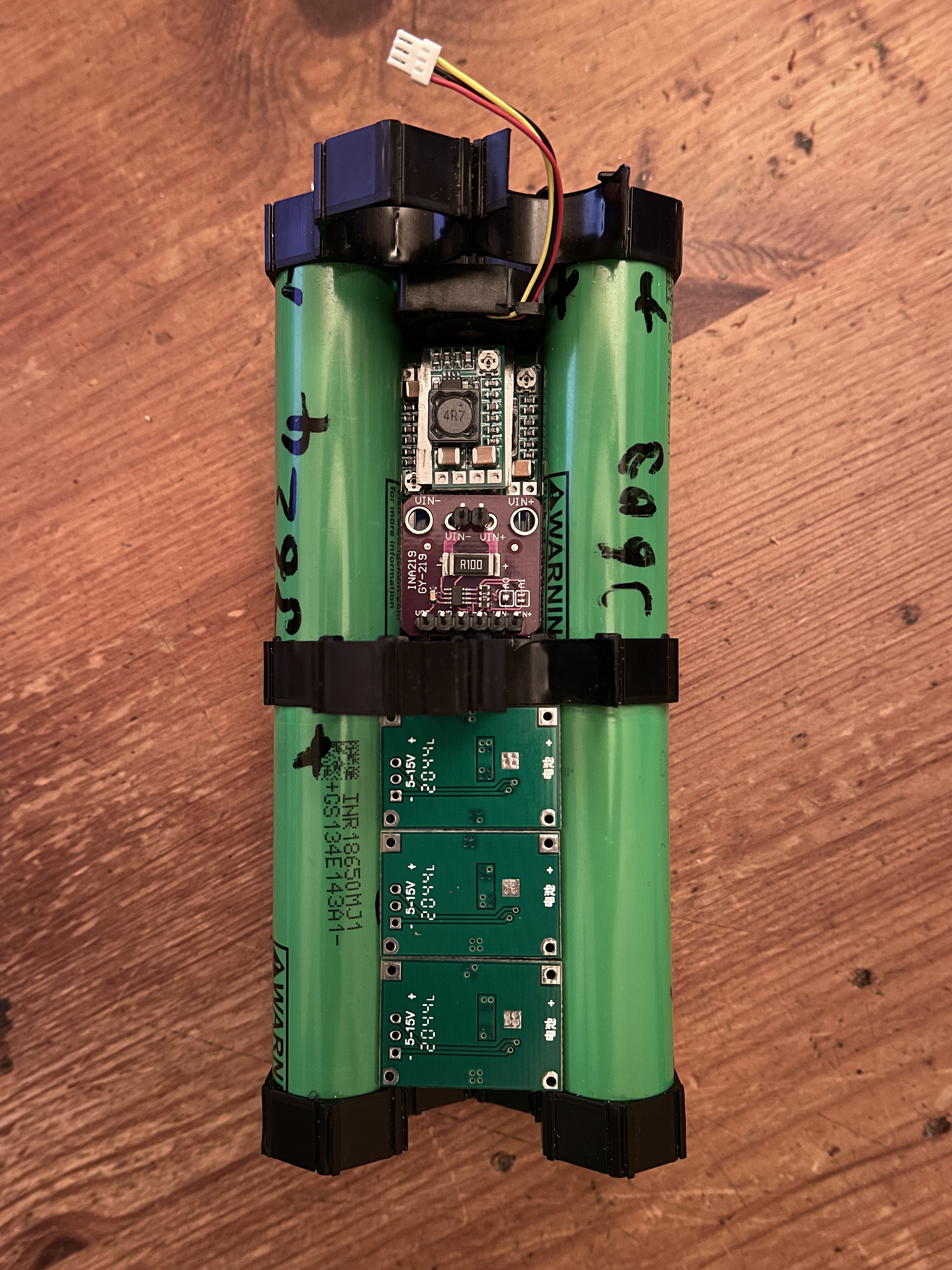
    Layout of Battery pack, power & charging boards inside the Thermal Duct, that the empty battery slot creates.
    Components are mounted on Aluminium heatsink that goes from top to bottom with maximum exposed surfaces to the Airflow.
    There are two levels of PCBs in this design. 3x 2S 2A Chargers(?), 4x 3A voltage buck converters, INA219 + INA260, 400w PWM Controller, 2S 20A Protection/Balance Board. Hoping Air will still flow ok. 
    Also still figuring out the power path for charging.
    Loading Screen
    Loading Screen (random selection of 12 different screens), shows loading errors and reset reason
    Progress with the UI:
    It's still not very beautiful, but already does almost everything that was planned. 
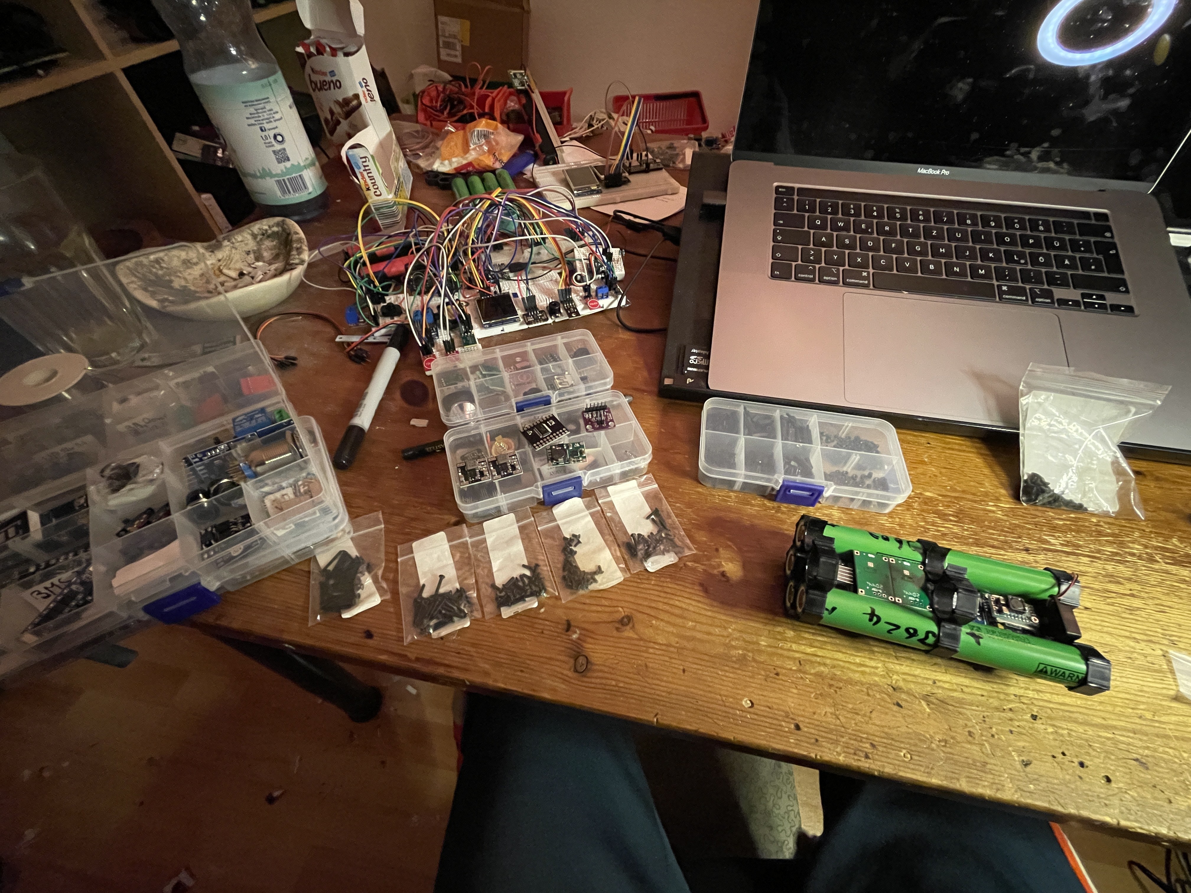
    Battery Pack tinkering & Electronics Prototype
    Battery Pack tinkering & Electronics Prototype
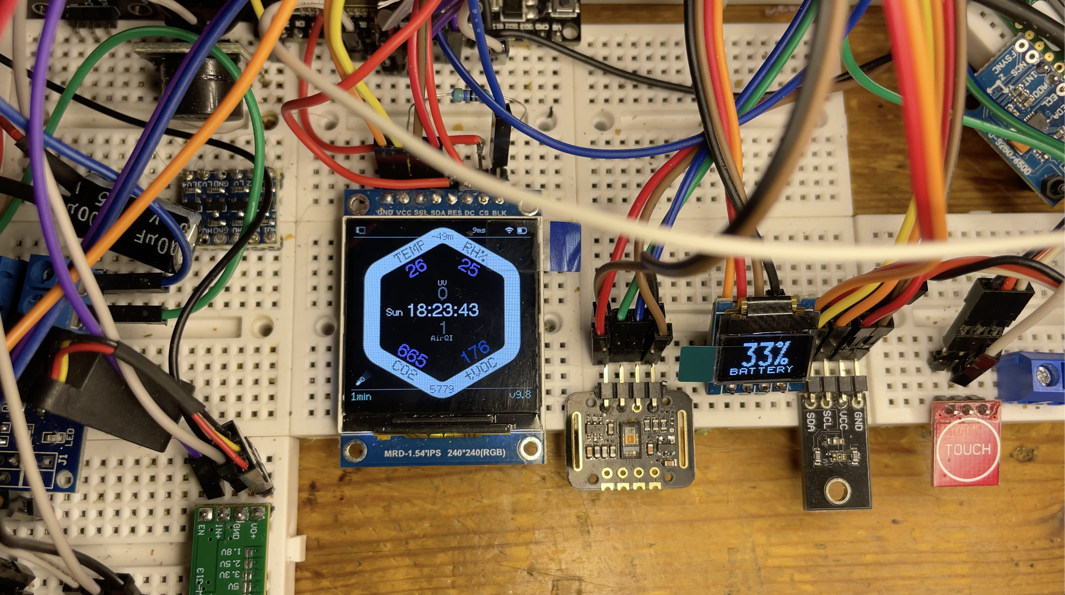
    Home Screen displays most important Data Points
    Home Screen displays most important Sensor Data.
    The whole System has a warning Screen for critical Over/Under - Temperature, Voltage, Current, Wetness values and sets everything into Low Power / deepSleep modes.
    Phone-like Status Bar for SD card, Logging, Fan, WiFi, Battery, FPS, Lamp, time since reboot.
    Small 0.49" Screen cycles through sensor values, shows alarms and indicates charging.
    Read more »

View all 16 project logs

Enjoy this project?

Share

Discussions

Daniel He wrote 07/25/2021 at 04:03 point

Cool project!

Since it is an apocalypse companion, I would also suggest a geiger counter feature for potential nuclear winters.

  Are you sure? yes | no

eBender wrote 07/26/2021 at 10:33 point

oh yea definitely! already looked into that, the good ones i found are pretty big and don't fit for now, unless i remove batteries.

there is a full list of more feature ideas at the bottom of this post:

https://hackaday.io/project/180257-h6x-pod-2021-hackaday-prize-entry/details

edit: now also in the details of this project page.

  Are you sure? yes | no

Esteban wrote 04/26/2021 at 13:38 point

Genius design and great idea!

  Are you sure? yes | no

eBender wrote 04/26/2021 at 13:58 point

thanks man!

  Are you sure? yes | no

setCREATE wrote 04/25/2021 at 20:31 point

Really cool Idea! For the controller chip, have you thought of using an MC60 module? it has the SD Card, GPS, GSM, and many other features already on itself, it can save you a lot of space.

also, does this thing have a sleep mode? for like expanding the battery life to some crazy amount of time?

  Are you sure? yes | no

eBender wrote 04/25/2021 at 21:09 point

hey thanks, good suggestion! i have not seen that particular model yet, but i have considered similar modules. It is almost the perfect solution for this (plus would add GSM), but i think after the arduino phase i'm going to go one step better and design a custom pcb in the perfect hex shape with those components and better power management, i'm still pretty limited by my expertise, though. 

But next up is finishing the prototype as i have it, to test functionality, usability and feasibility.

sleep and power-saving modes are already implemented for the esp32 and most of the sensors (the ones that have an easy sleep/power-off mode in the code). Toggling deepSleep via html app and then working off of the RTC and ULP timer with configurable wakeup/sleep times. I (very loosely) estimate the battery life to be over 4 weeks on low-power/deepSleep mode with interval logging, probably longer (if its not used for device charging or lights)

  Are you sure? yes | no

setCREATE wrote 04/26/2021 at 06:00 point

That's great, keep it going.

  Are you sure? yes | no

Similar Projects

Does this project spark your interest?

Become a member to follow this project and never miss any updates