Matthew Begg
-
Revision A board testing
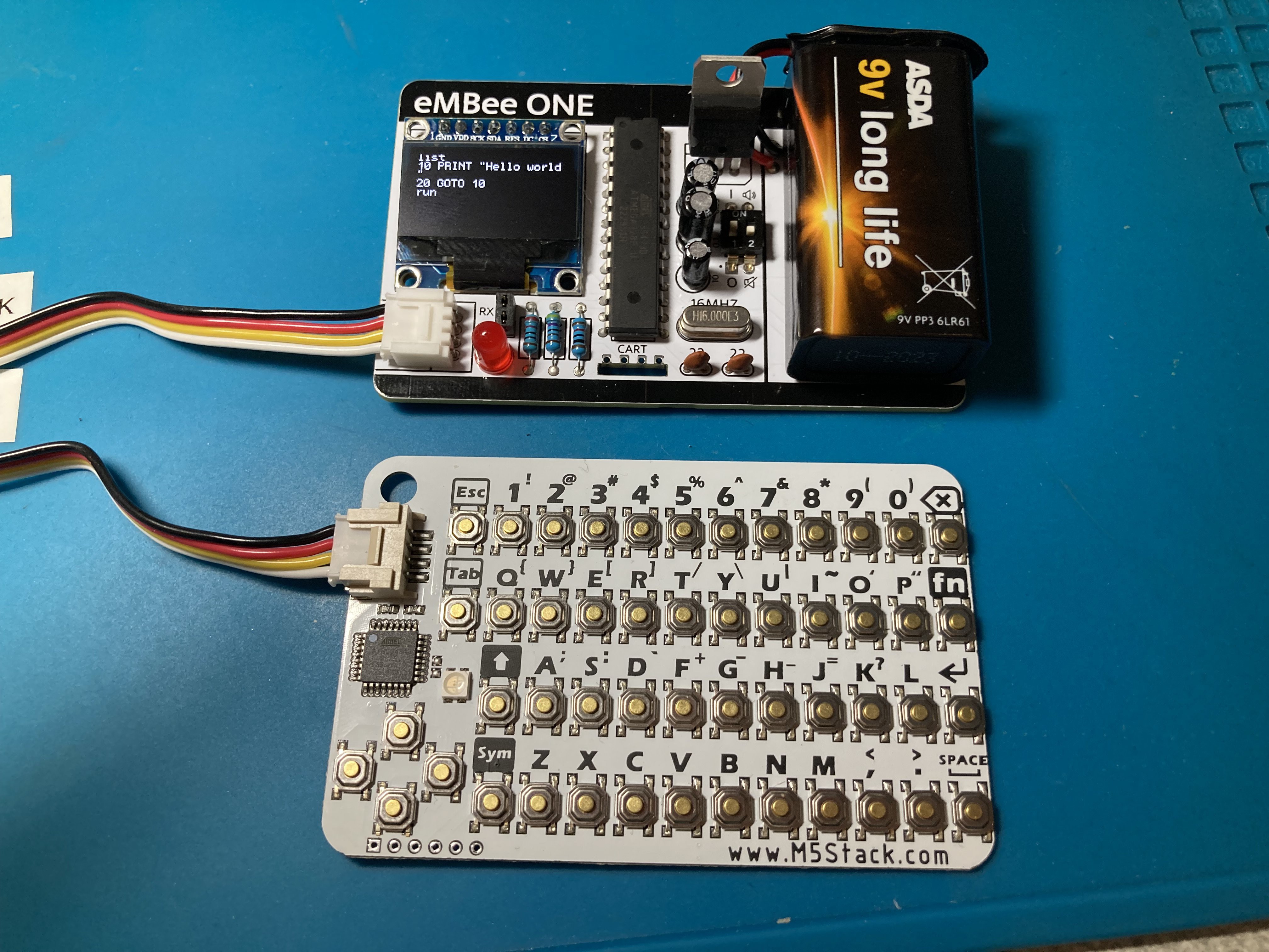
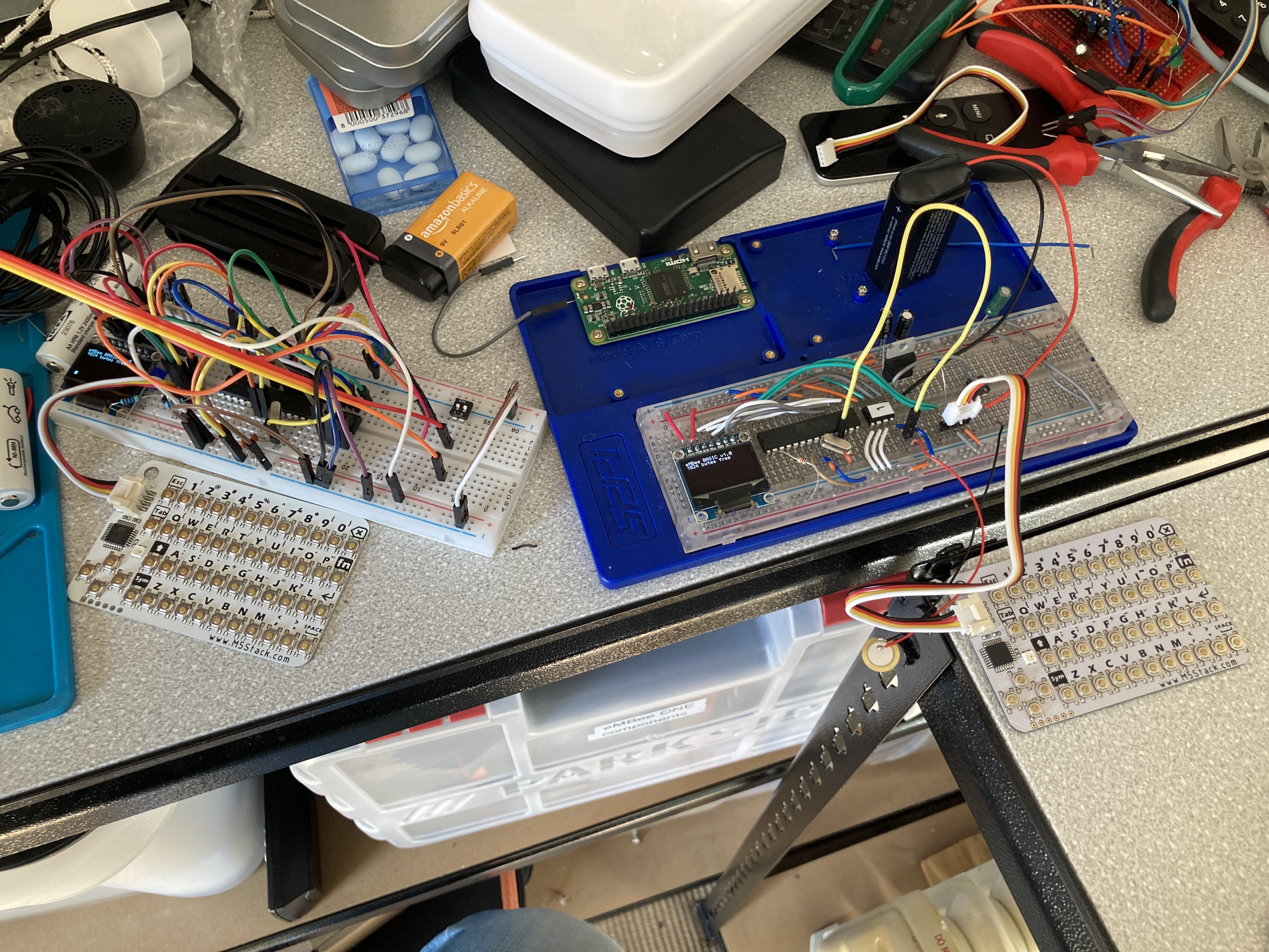
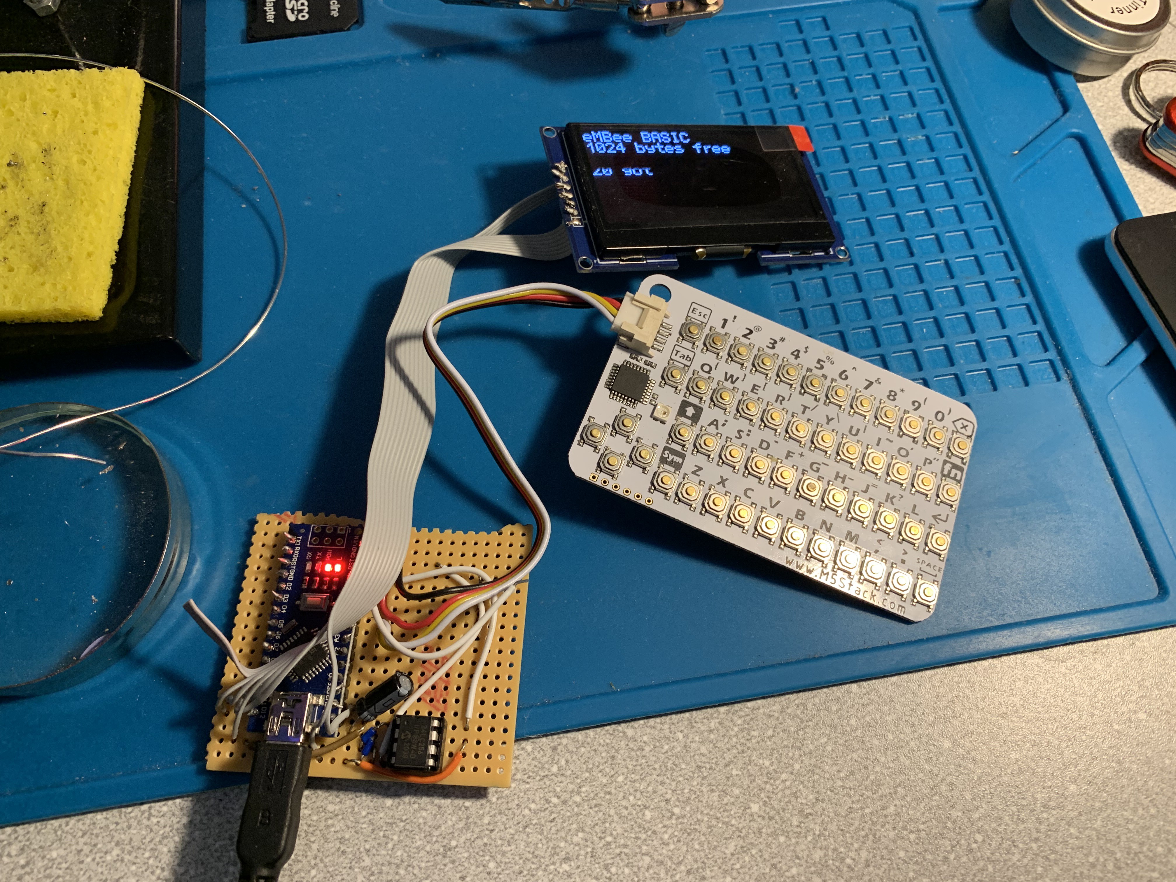
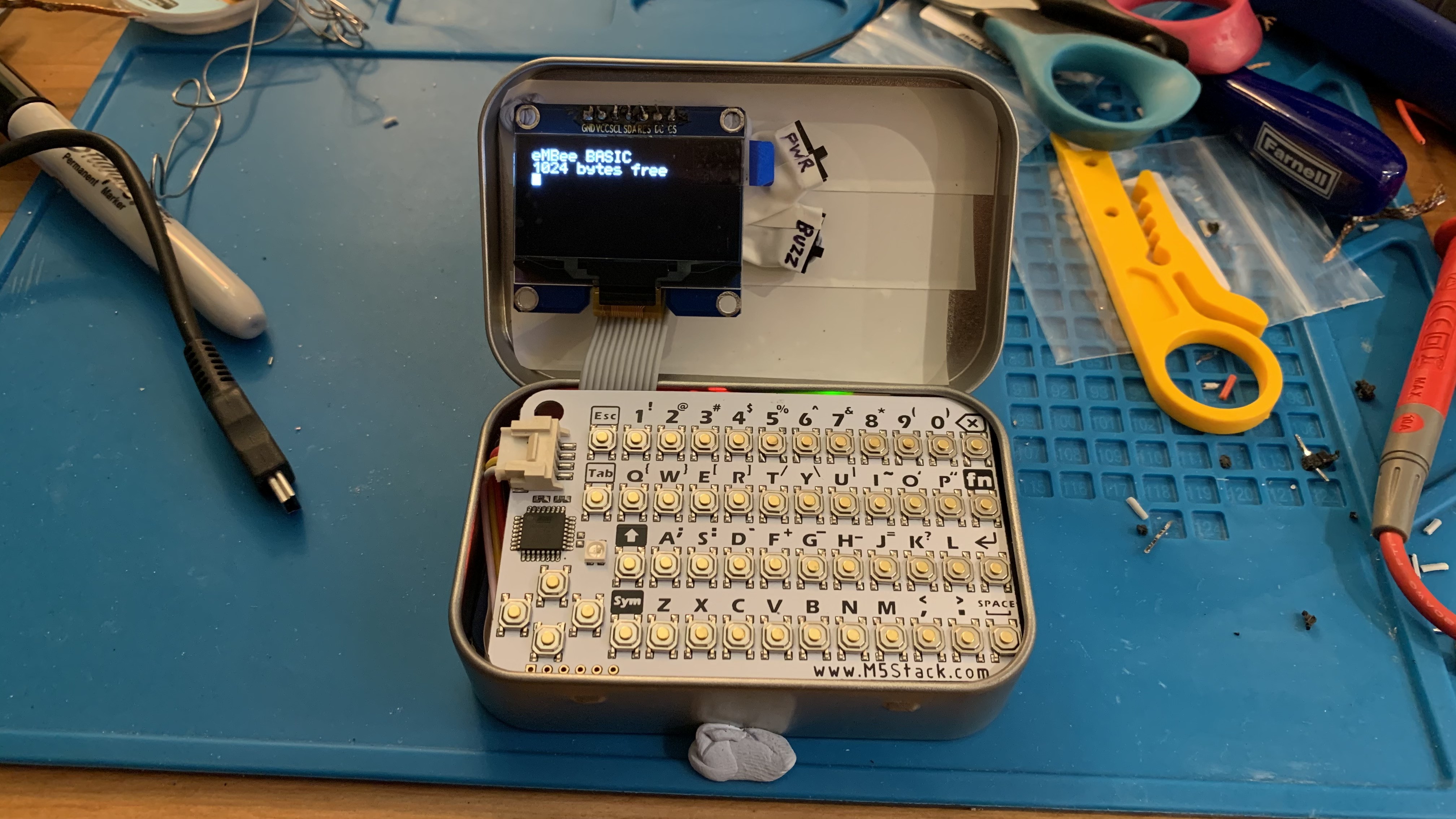
08/30/2024 at 09:25 • 0 commentsI've now built the first 'production ready' eMBee ONE using one of the 5 Rev A boards I got from JLCPCB. There was a tense moment before I flicked the power switch on for the first time and...
...it worked!
![]()
There are a number of issues that I'll definitely need to sort out before they're ready to distribute:
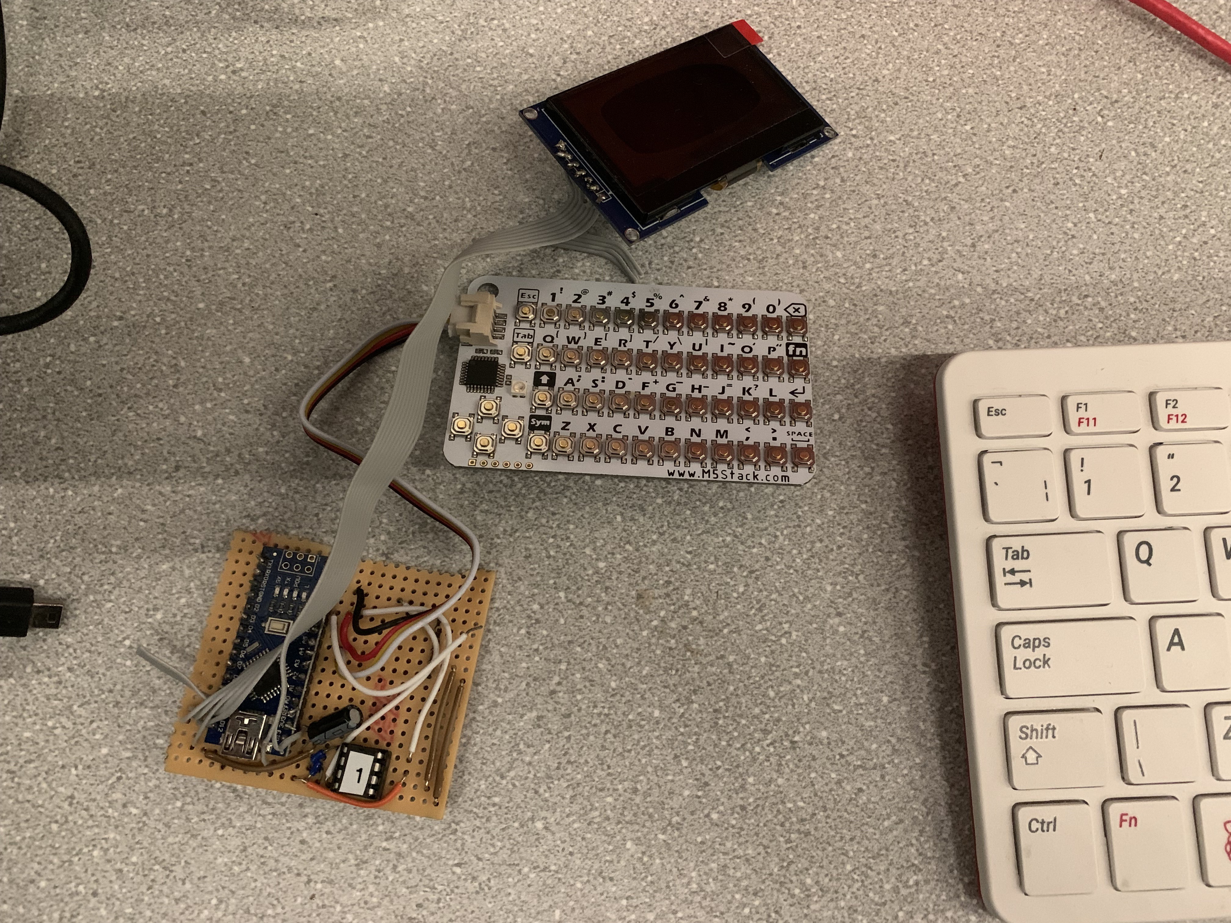
- The board is too wide to fit in an Altoids tin! It's 85.6mm which is apparently the correct size for a credit card, but compared to the CardKB it's about 2mm too wide. So revision B will be 83.6mm wide. Other dimensions are fine.
- As mentioned before, the RX/TX pins are a bit pointless without a GND connection, so the next revision will have 3 pins instead of 2.
- The introduction of 'eMBeeLINK' communications means the list of commands and functions will need updating to include SEND and RECV$
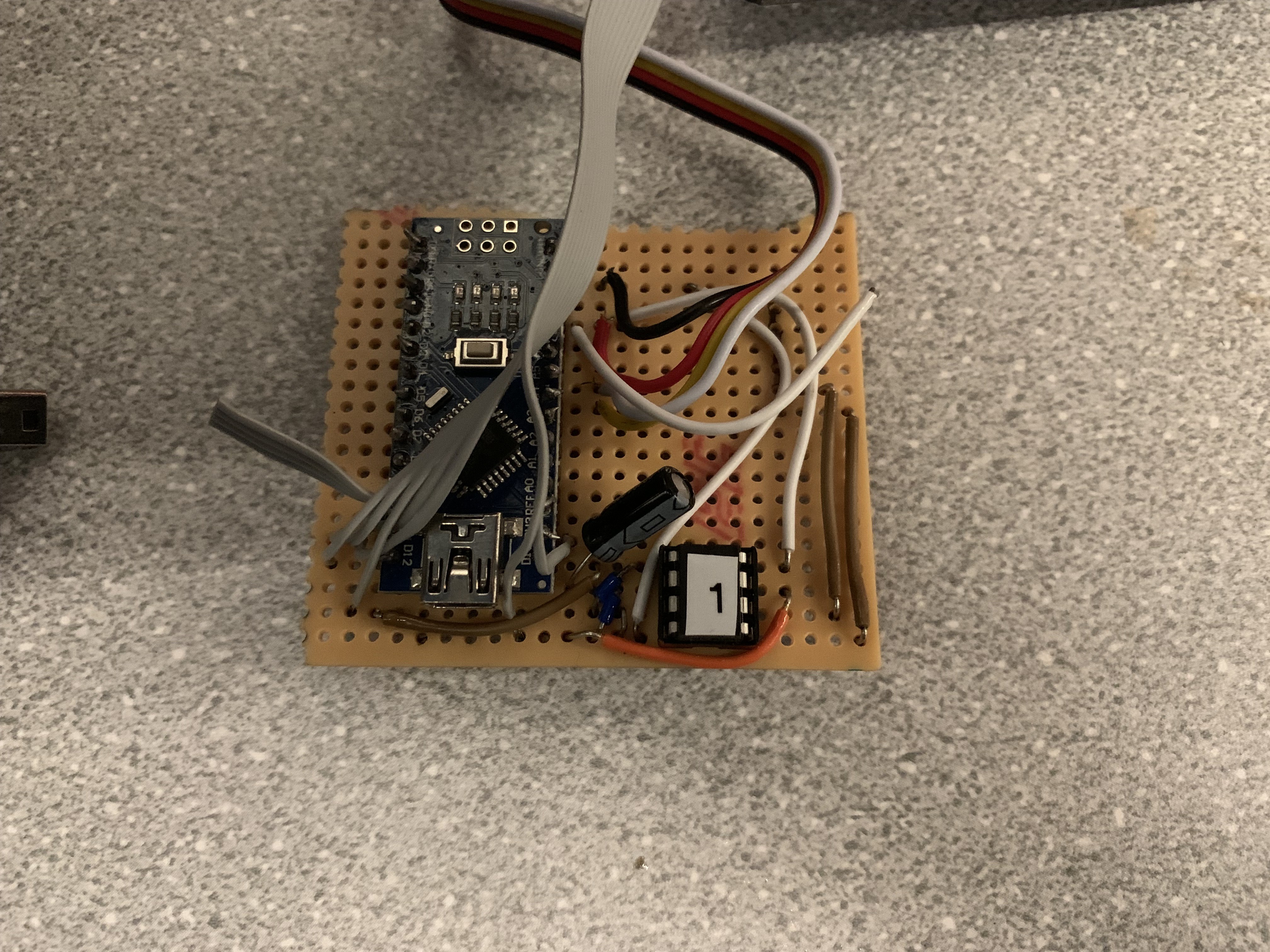
- When I tried to solder in a 28-pin DIP socket, the two rows of pads were too far apart. So I had to solder the chip directly onto the board. Not a good idea for the finished product, so I'll need to use a narrower part in the design so the socket can be used
- Similar issue with the on/off switch - ended up snapping the legs off one before getting the bend just right. So the pins need to be closer together on this.
- Speaking of the on/off switch, it's only now I've got it in place next to the tall capacitors and 9V battery that I realise how incredibly hard it is to reach! You have to have baby fingers to get to it. So in the next revision I'm going to move it - probably swap it with the 4.7K and 10K resistors.
- Even though I was snipping the extra length of leads after soldering components, the board still stands proud of the surface it sits on. So I'm going to investigate small rubber feet for the corners. Maybe even stretch to 4 more for the keyboard too.
- The L7805 voltage regulator looks so massive - I'm going to source a smaller TO-92 package version to make better use of the limited space on the board. This might free up space for more ports.
- The markings around the keyboard port look a bit wrong so I might remove those.
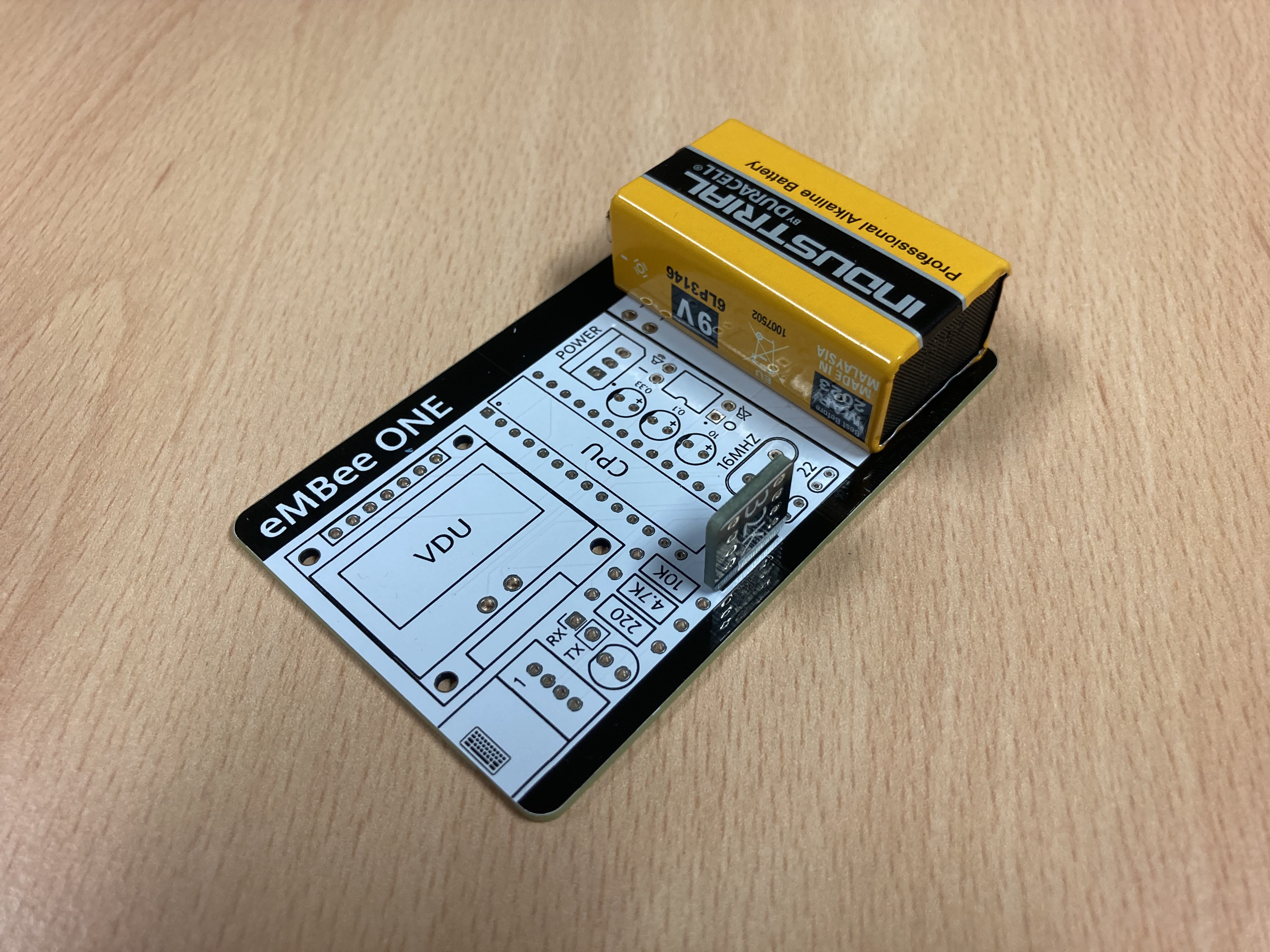
- Once the 9V battery is in place, it completely covers up the programming header. So I'll need to move that further down.
Hopefully won't take me long to get those issues ironed out and get a new set of boards ordered. In the meantime I'm super pleased that the general design works! Still to test:
- The speaker (I forgot to solder it in BEFORE adding the screen - oops)
- The cartridge slot
-
The first boards have arrived!
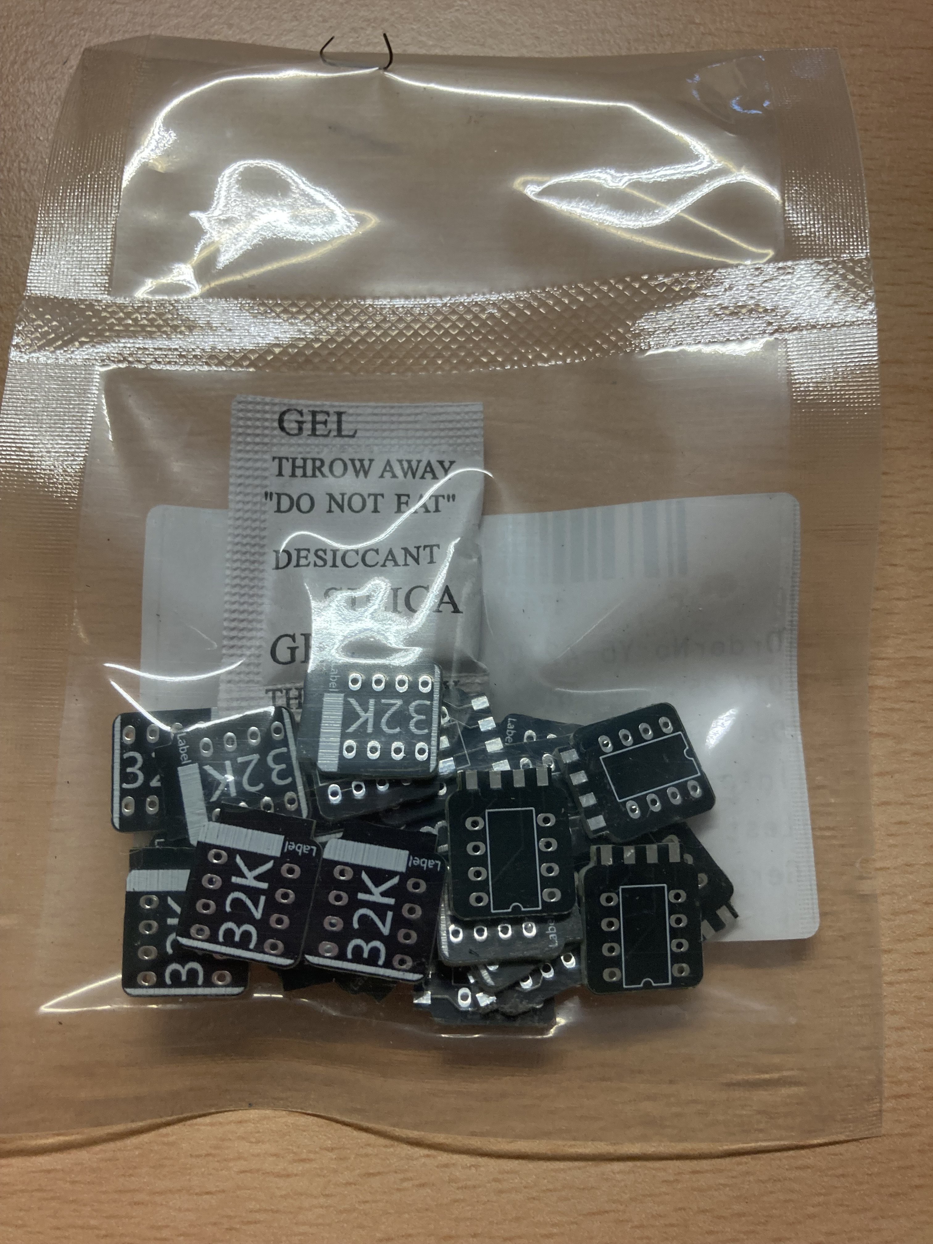
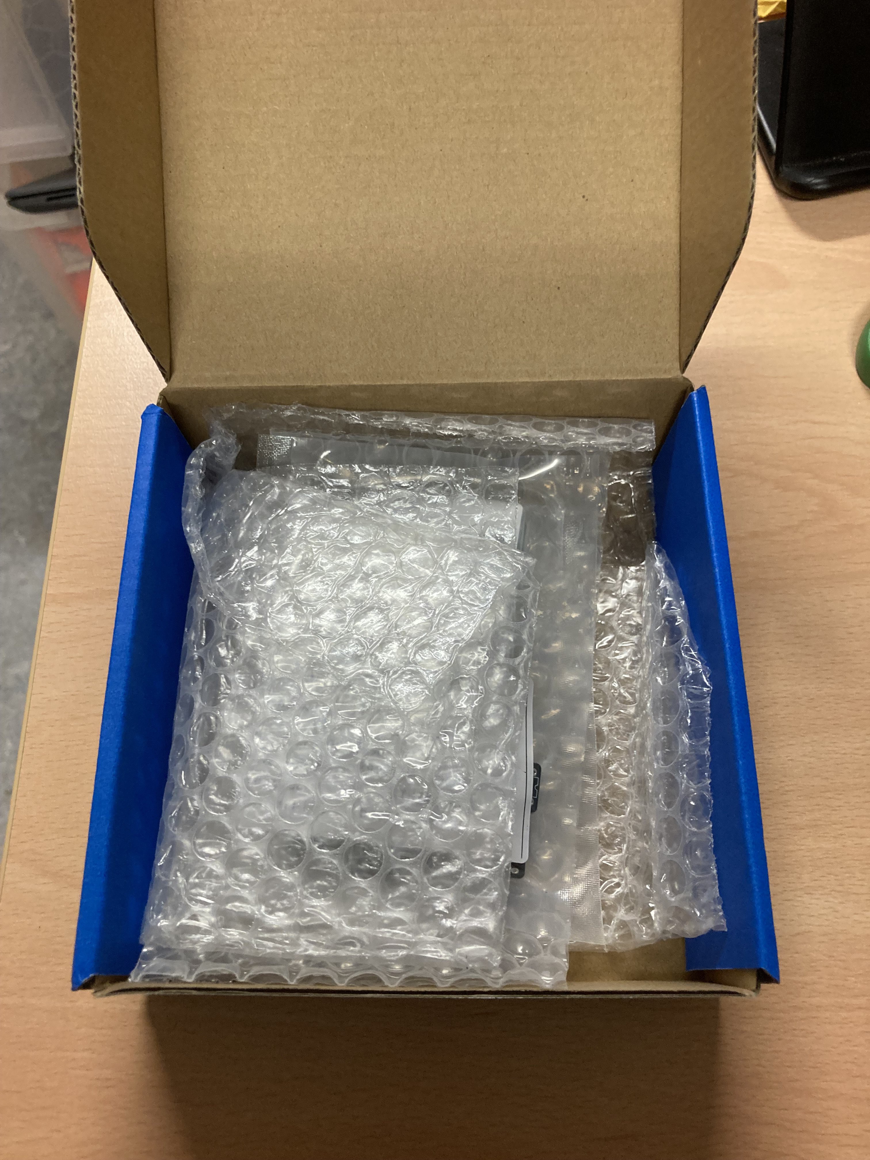
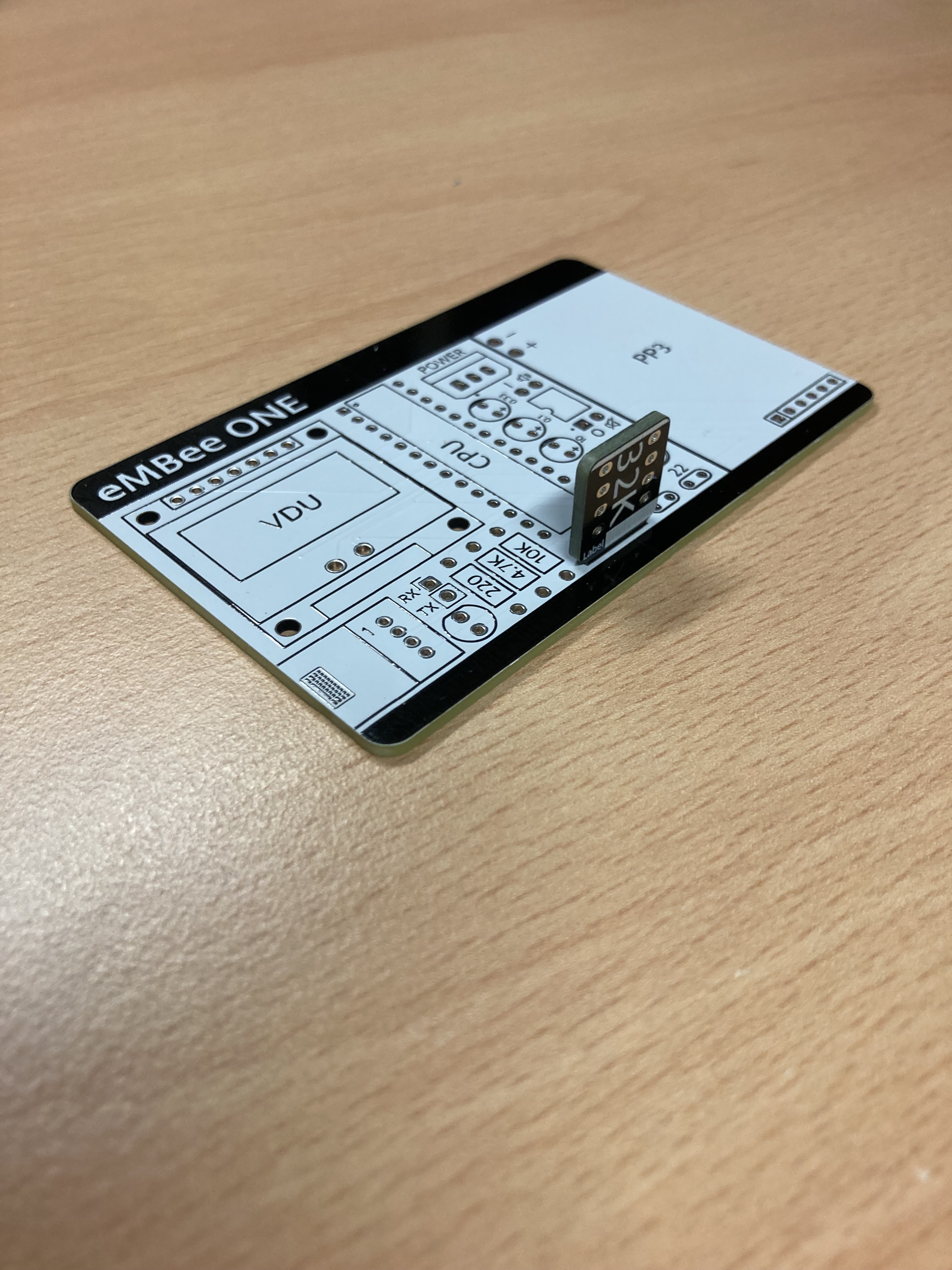
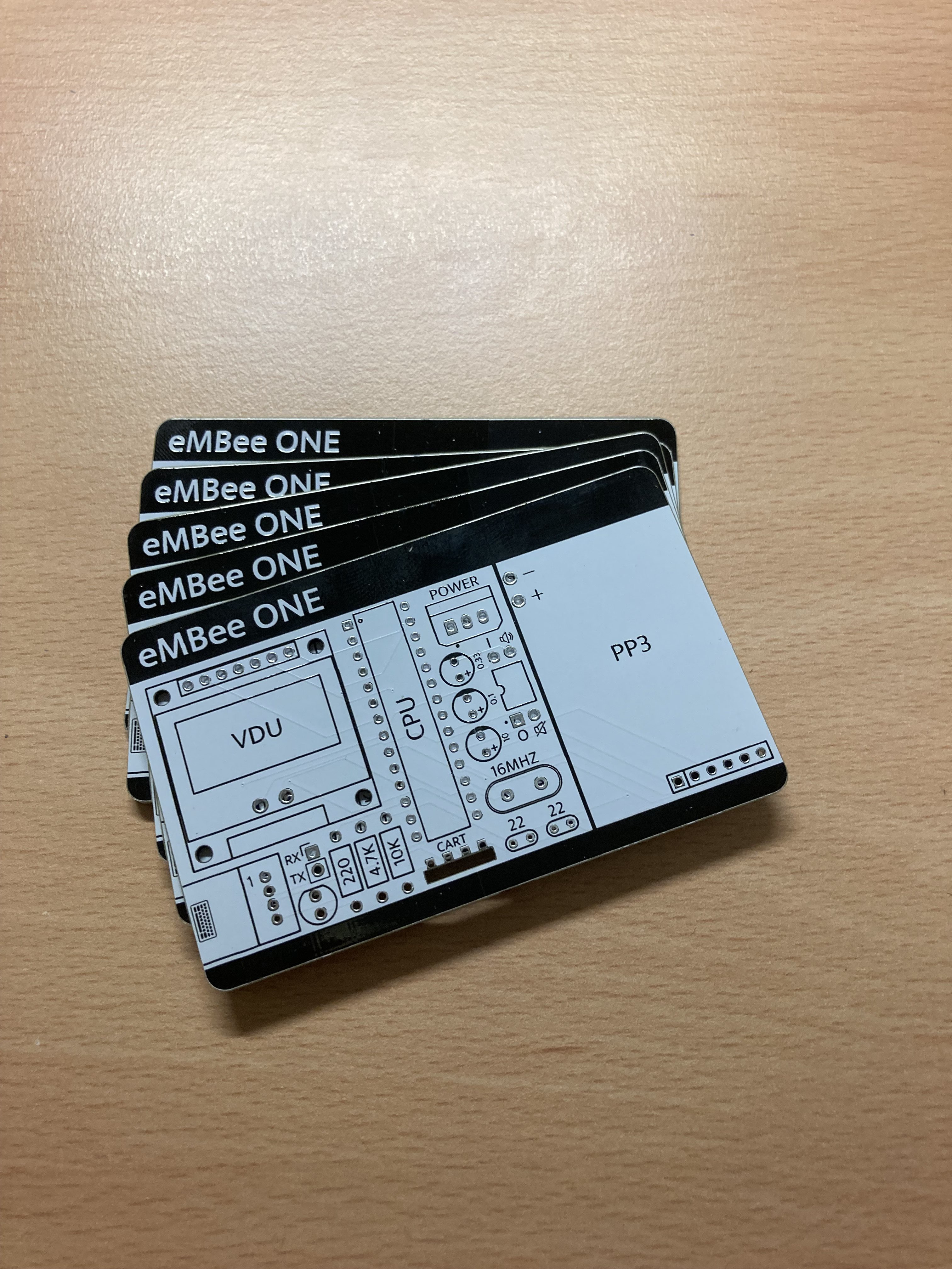
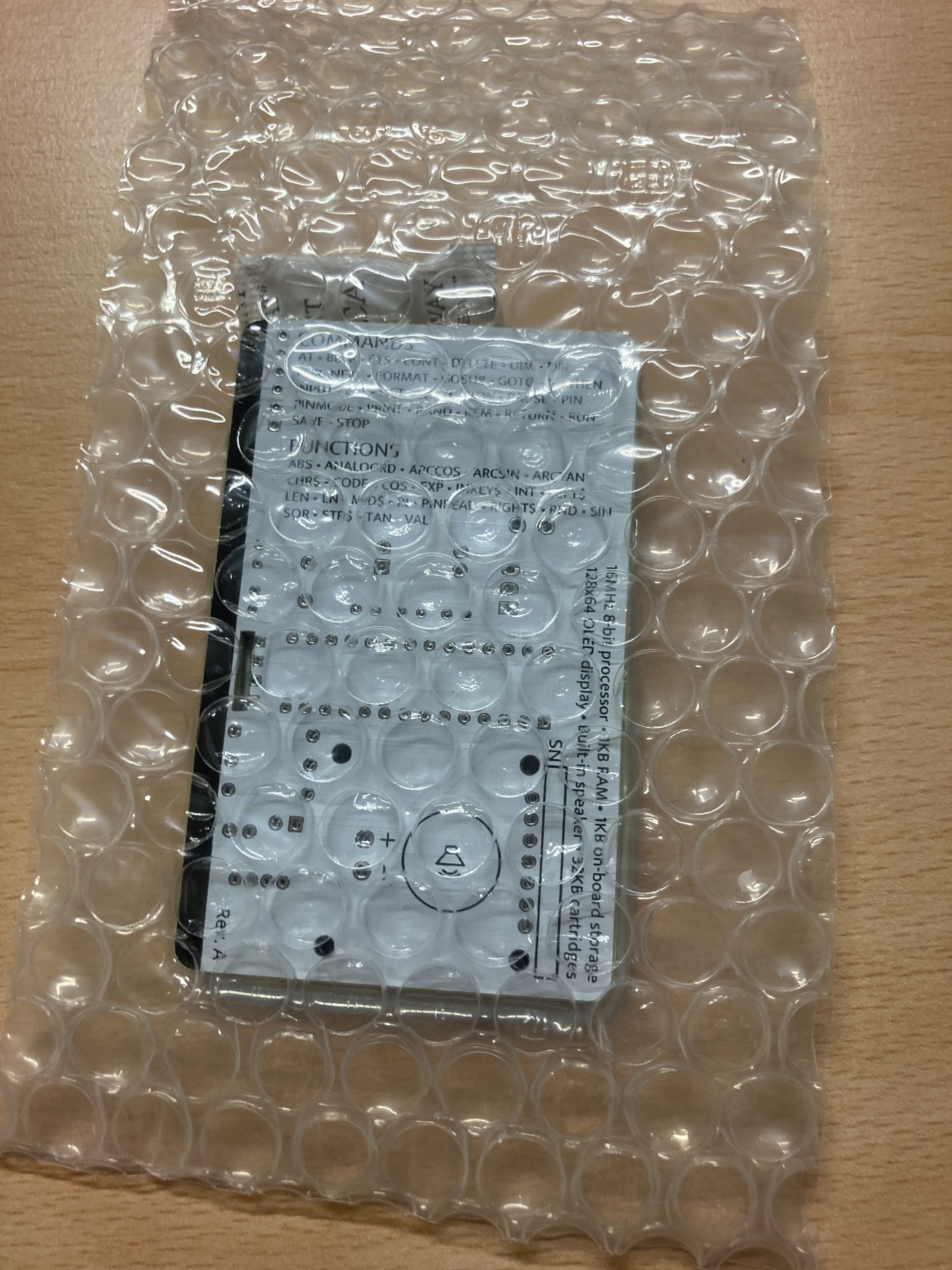
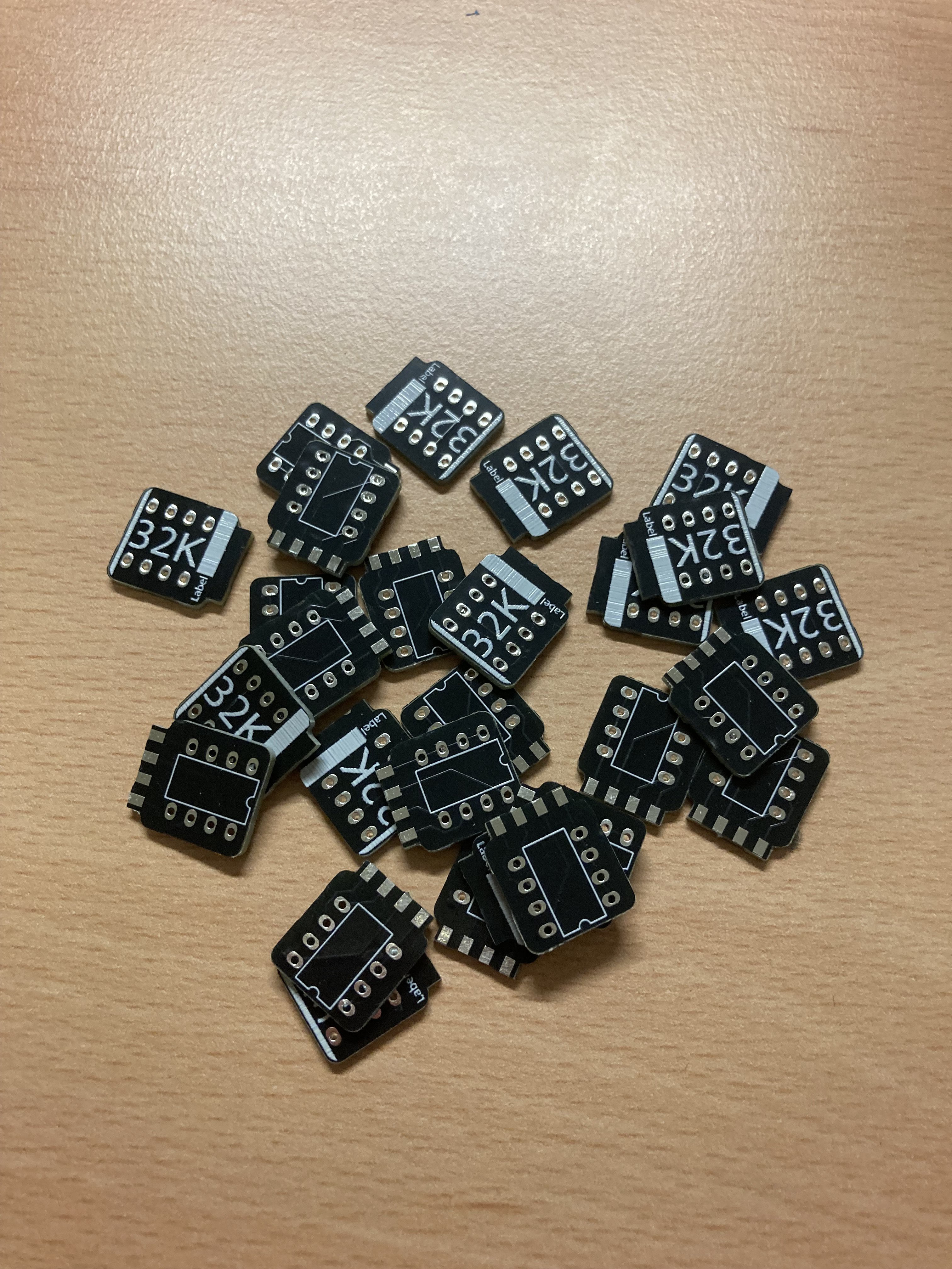
08/27/2024 at 13:34 • 0 commentsVery impressed with the speed and quality of the JLCPCB service - the boards look great! They look exactly like they did on screen in easyEDA. Can't wait to test them. Looks like the cartridge PCBs fit perfectly - will need to work out the best way for them to electrically connect once inserted. Was thinking conductive paint in the hole, but now thinking tiny wrapped wires.
![]()
![]()
![]()
![]()
![]()
![]()
![]()
![]()
-
Big update after a hiatus
08/16/2024 at 21:48 • 0 commentsThe eMBee ONE is nearing production! A lot has happened since the last log entry, so here's a brief catch-up:
- Successfully made the transition from using Arduino Nano modules to standalone ATMega328P chips. Had to learn how to program them using an Arduino Nano, and what supporting components are needed.
- Decided on the 9 volt PP3 battery as a power source. Calculated battery life to be at least 30 hours on an alkaline battery. Decided on the L7805 voltage regulator to get 5V.
- Chose a 2 way DIP switch for power and turning the sound on/off.
- Decided to make the external EEPROM into a removable cartridge
- Realised that the instability of the previous eMBee ONE prototypes stemmed from not having a pull-up resistor on the I2C bus. Now including a 4.7k resistor
- Built not one but two breadboard-based prototypes. Both ran for extended tests with no issues.
![]()
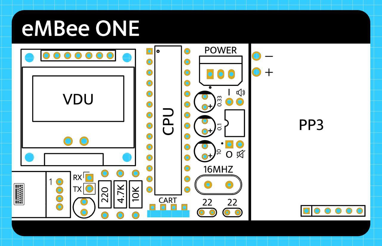
- Designed and ordered the first revision of PCBs! Using easyEDA, I designed the whole computer to fit on a credit card-sized PCB. Just connect a CardKB keyboard via the grove connector and plug in a PP3 battery. Ordered five PCBs from JLCPCB - should be here in the next 2 weeks or so.
![]()
- Started drafting the listing for Tindie. Will wait until I've received the first batch and successfully tested them before offering the remaining 4 for sale as 'first edition'! That's the point at which I'll send a tip to Hackaday to let them know about the project. That's also when I'll share the Gerber files on this project page. The software is already available on my GitHub.
So as you can see - there's been a lot of progress! I'll add another log once the PCBs arrive.
-
Back to basics...no soldering required?
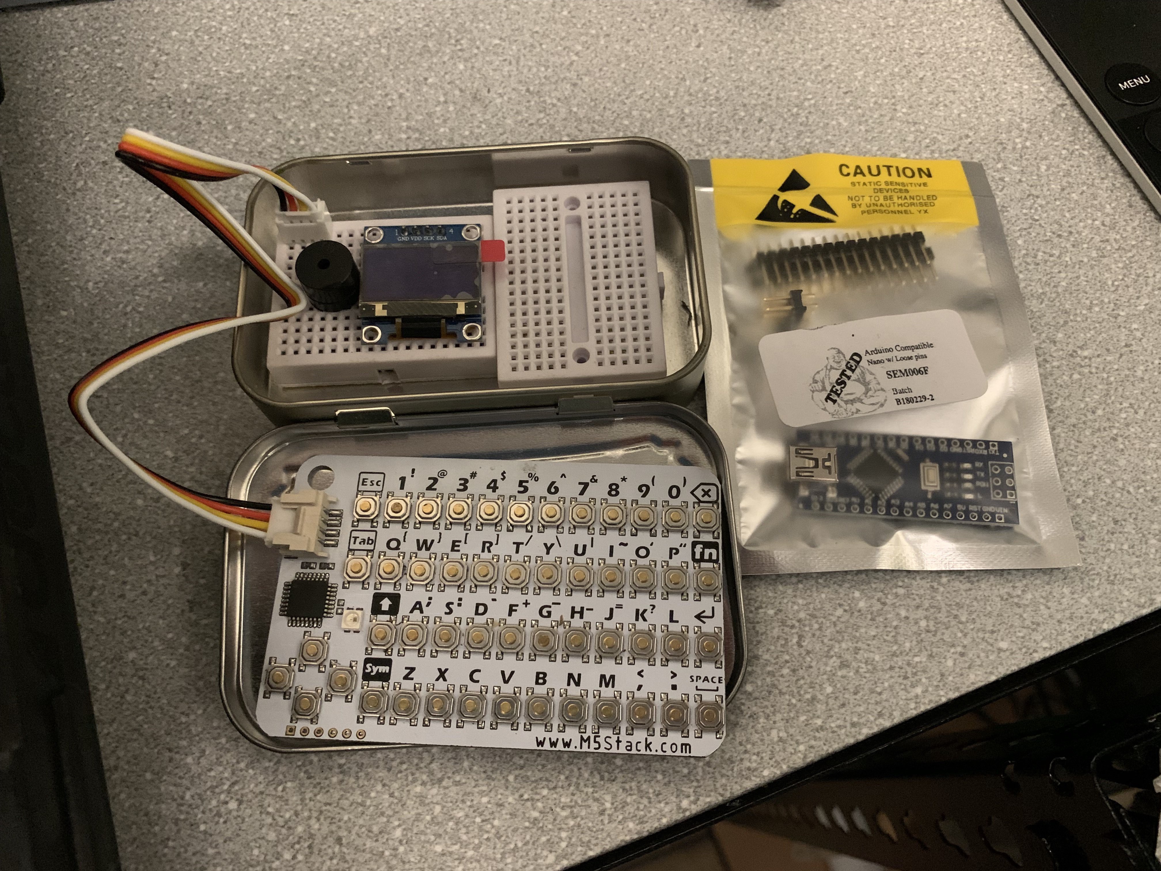
07/18/2022 at 22:04 • 1 commentDespite being distracted by other projects (including the eMBee TWO with colour screen), I keep being drawn back to the simplicity of the eMBee ONE and the 8-bit aesthetic. One aim is for this to be a simple project for anyone to build. Perhaps it would be possible to build this (and fit it inside the Altoids tin) WITHOUT soldering? I did some initial research into this idea, and it looks possible. The image below shows a real Altoids tin (cinnamon flavour if you must know!) with two small solder less breadboards inside. I've placed the display, keyboard connector and buzzer but didn't have an Arduino Nano with headers attached. You can see a fresh unheadered one in a bag there. But you can buy them from eBay and AliExpress with headers already attached. So this is looking very promising. Still begs the question of how to power it and still have it all fit in the tin. Also can the innards be made tidy once the hotchpotch of jumper wires are attached?
![]()
Couple of issues to consider:
- The PCB connector for the Grove cable (from the CardKB keyboard) isn't the correct pitch for a breadboard. I've had to bend the pins a bit and although I think it works, it's not a very stable connection. A slight knock and it comes out.
- I haven't settled on the orientation of the two mini breadboards
- The location of the keyboard connection will affect how easily the lid closes
- I've gone back to the ubiquitous 0.96 inch 128 x 64 OLED mainly for cost and size reasons. I know it isn't as eye-catching as the 2.42 inch display but it's a lot more affordable and keeps the rest of the components visible.
What do you think to this slight change in direction towards non-soldered kits?
-
eMBee ONE update - all working but doesn't fit
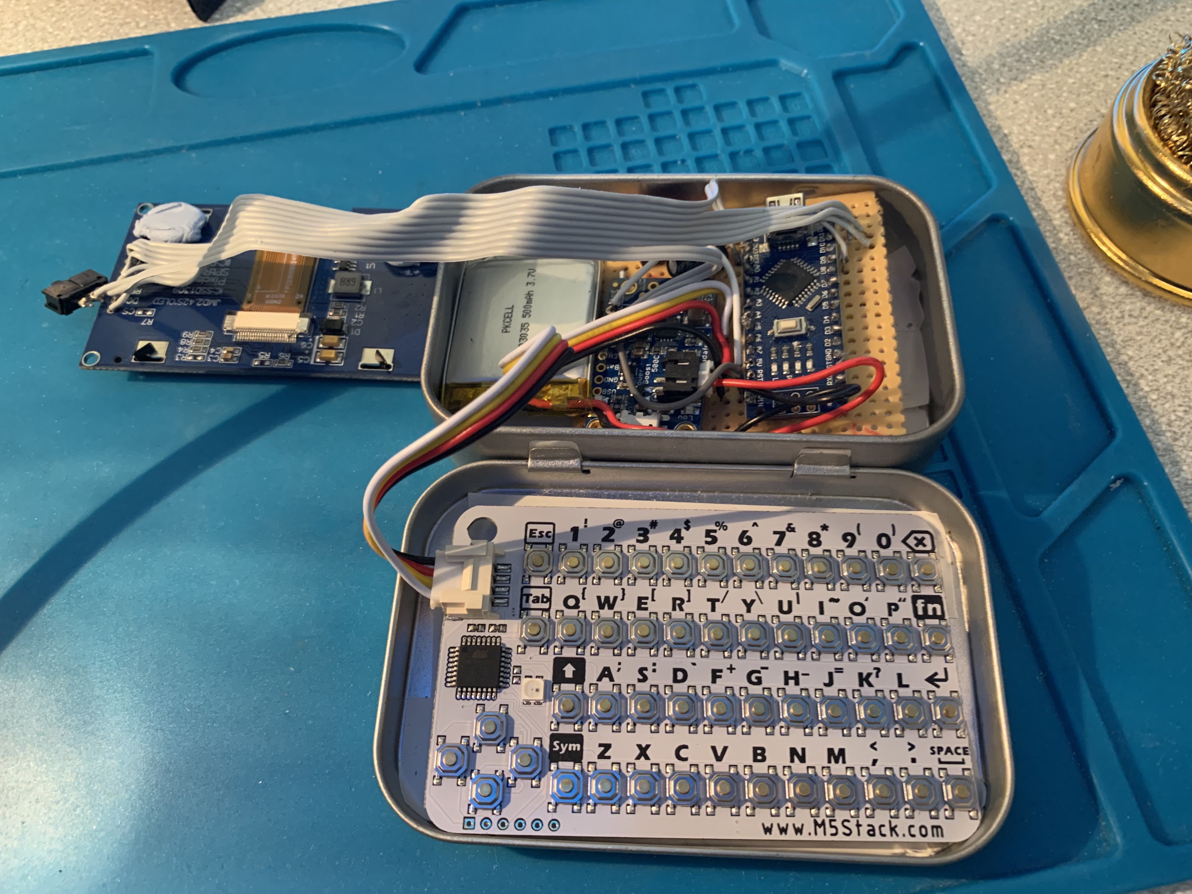
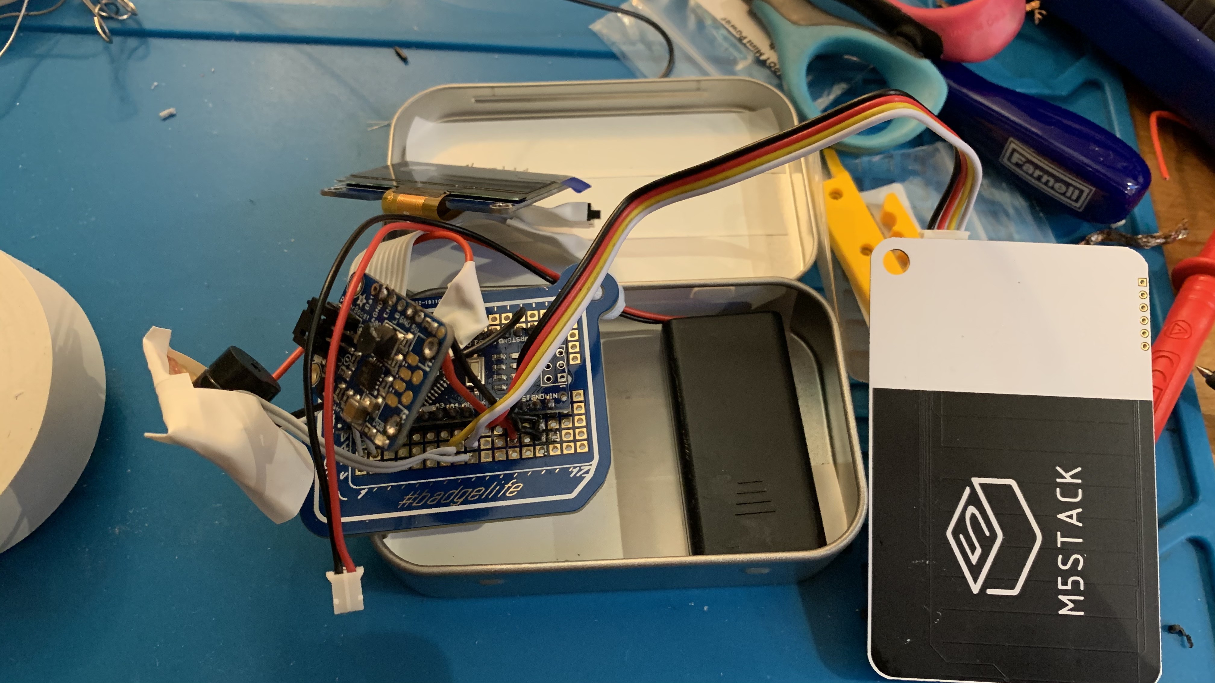
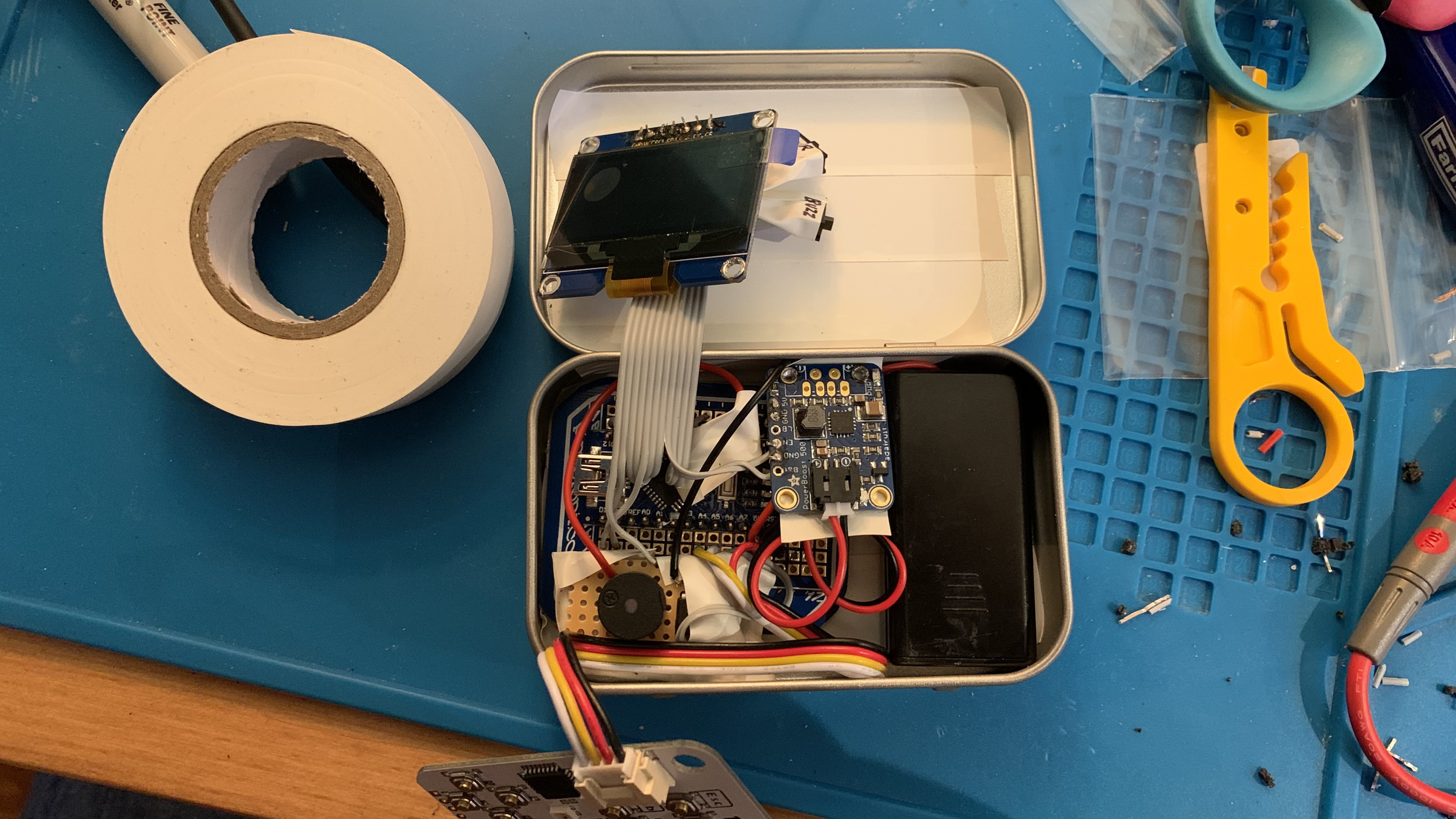
03/12/2022 at 15:34 • 0 commentsSorry for the long pause in log entries - I actually had everything working a couple of months ago. So it now has a lipo battery connected, and can operate standalone in the tin. However, I had made the ribbon cables for the keyboard and display too long, which means they take up too much space in the tin and the lid doesn't close. Look how long they are:
![]()
What this image also shows you is my new plan for swapping everything around in the tin. So the keyboard is now in the lid, and the screen joins the main board in the main part of the tin. There are a few reasons for this, but mainly so typing is more comfortable, with a solid surface to type on rather than putting pressure on the other components every time you type something.
As I started to chop the wires down, my soldering iron bit broke in half! Then had to wait for it to cool down before replacing it. And that's when my brain started wandering into the possibilities of designing a custom PCB, using cheaper but more powerful hardware...
Introducing the eMBee TWO!
I'm still planning to finish the eMBee ONE as a one-off piece (just a few wires to shorten so the lid closes), but if you want to build a pocket computer that boots into BASIC, then the eMBee TWO will be the project to follow.
Thank you to everyone who followed the project, and I hope to see you for the next generation of the eMBee platform!
-
It's aliiiiiive!
10/28/2021 at 22:21 • 0 commentsI finished connecting the 2.42 inch OLED display to the board. One difference this time: I added a 47uF capacitor across the 3.3v and GND to hopefully stop the display from dimming. And it appears to work!
So the display, keyboard and BASIC are working. Currently just powered via the Nano's mini-USB socket. Still to come:
- External EEPROM (you can see it in the pictures but I need to 'reformat' the chip before it'll work properly)
- Buzzer (maybe switching to a flatter disc-type piezo sounder to take up less space in the tin)
- Power circuit with LiPo
- Possible switches for power and sound
- Fitting it all in the tin
So plenty to do! In the meantime, here are some images...
![]()
![]()
![]()
-
Return of the eMBee ONE
10/17/2021 at 17:55 • 0 commentsFinally got back in the shed and got the eMBee ONE project back on track. Soldered the new 2.42 inch OLED display onto the (longer) ribbon cable.
![]()
Next step will be getting it running again before assembling the new power circuit and lipo battery.
-
All quiet at eMBee HQ!
03/22/2021 at 09:45 • 0 commentsHi all,
Just a quick update as you haven't heard from me in a while. Since the last update, I have started to move the project to a single veroboard/stripboard design, still using an Arduino Nano module, CardKB keyboard, 24LC256 EEPROM etc. But because I've changed my mind so much in the past, I've ended up struggling to desolder various pins and wires from each module (particularly the 1.54 inch OLED and the Adafruit PowerBoost). So I thought to make it easier, I'd order another screen. Which made me debate going back to the 'big' 2.42 inch OLED or stick with the 1.54 inch. You'll remember that my previous 2.42 inch display kept dimming at random intervals. But I'm assured that isn't expected behaviour and it must've been a faulty unit. So I have reluctantly ordered another 2.42 inch display from eBay. Will take about a month to come, so not much will happen with the project until it arrives. But then it should be full steam ahead with a new final unit being prepared, and the 3D printed parts being designed. Exciting!
Previous comments on this project have included suggestions of various features to be added, which go beyond my original vision. Let me know in the comments below if you think I've got the balance right between simplicity, nostalgia and features.
-
The first prototype!
02/19/2021 at 10:35 • 0 commentsHello world!
Here is the first prototype of the eMBee ONE. Hand soldered, self-contained, and running from 2 x AAA rechargeable batteries. More pictures:
![]()
![]()
![]()
A few things to note:
- The screen is not where I wanted it to be. The idea was to have it centrally in the top lid, but I accidentally cut the ribbon cable too short, so it wouldn't reach.
- Two switches to the right of the screen: 'PWR' connects the 'EN' and 'GND' of the Adafruit PowerBoost to act as a main power switch. 'BUZ' is to switch the buzzer off/on.
- Fitting all those separate modules and prototyping boards into the bottom case is a tight squeeze. Future versions will definitely have the modules all on one prototyping board to make it thinner.
- The lid doesn't close. Partly because the screen is too far left and hits the CardKB GROVE connector, and partly because the modules are all separate and are too tall.
- When typing, the keyboard bends in certain places as it isn't supported underneath.
- The eagle-eyed among you will spot I forgot one connection - the VCC for the external EEPROM, so it currently can't access the 32KB of storage. However it's just a simple wire for that to work.
Demo program
Conclusion
Really pleased with this first prototype - it just about proves the concept works. And, as with all good prototypes, it shows me what needs to happen next:
- Use a custom-sized piece of prototyping board and attach the Nano, PowerBoost, EEPROM and buzzer to it. A single board will help with the space in the bottom half.
- Use a longer ribbon cable for the display so it can be placed centrally.
- The lid should close.
- Once the second prototype is working, my cousin can provide the 3D printed bezel for the top, and perhaps a 3D printed support structure to stop the keyboard bending while typing.
Let me know what you think in the comments below!
eMBee ONE pocket computer
A 1980s style 8-bit computer running BASIC. Includes OLED screen and a QWERTY keyboard. Oh, and the whole thing fits in an Altoids tin.