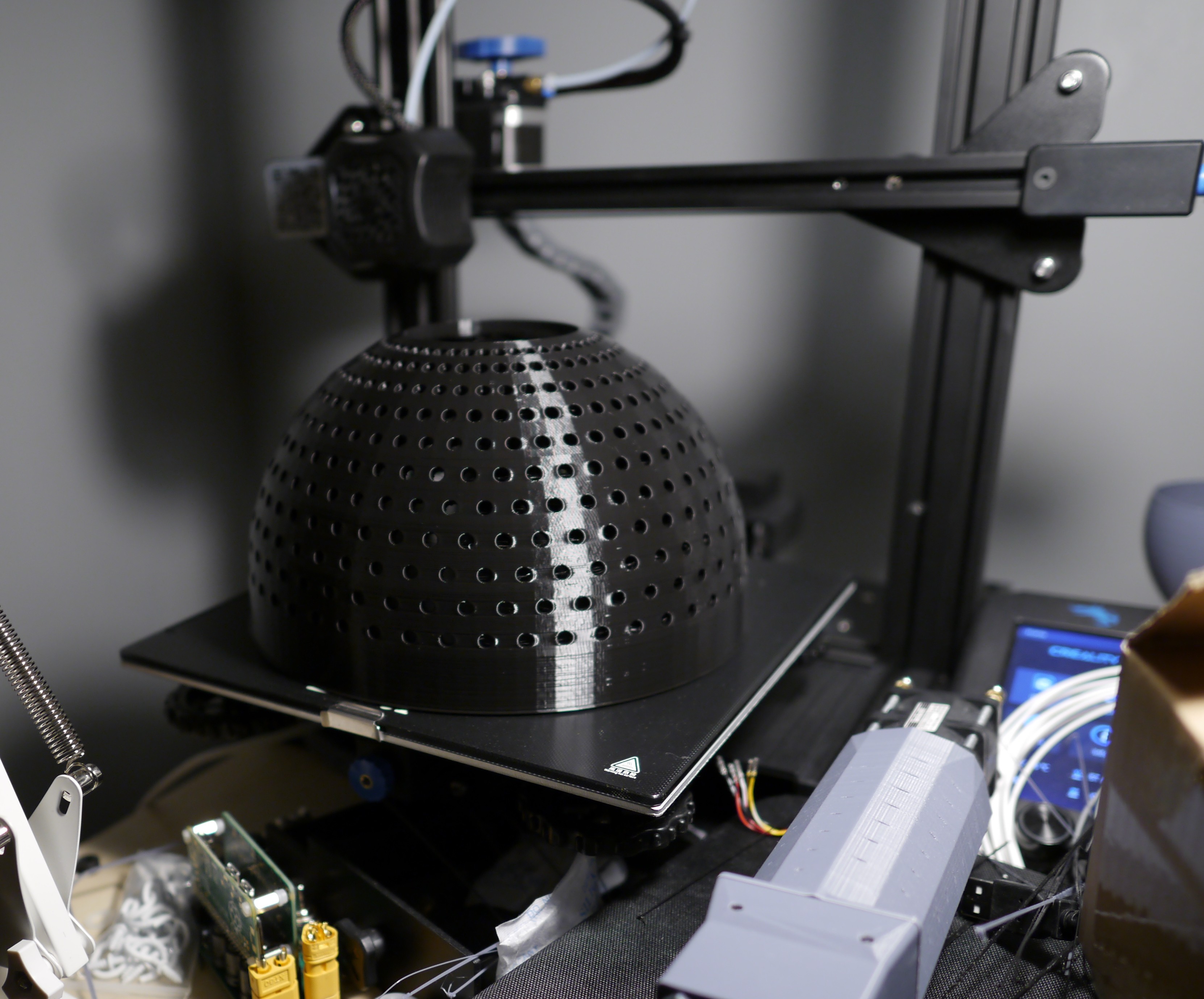
I've printed the Nocticron dome and found the 5mm LED's fit perfectly with the exclusive slicing tolerance. Much less painful than forcing them in with a crescent wrench. Unfortunately, I forgot the minimum focus distance of the Nocticron is NOT 4 inches. I'll need to print an adapter for my Macro-Elmarit lens instead.
I'll share a few more pics here.
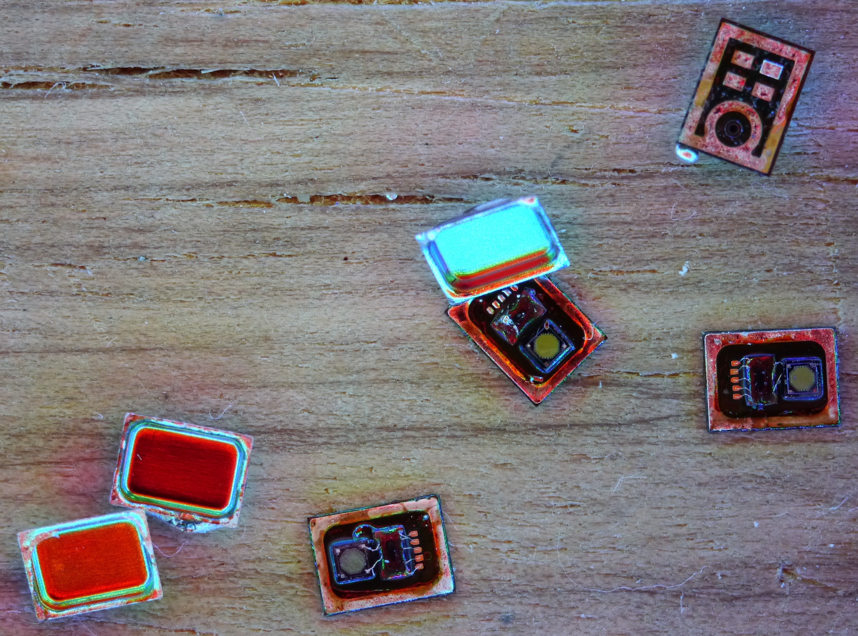
Here's a MEMS microphone from TDK which has a tough footprint. The wicking effect and possible solder-mask bridging to signal lines makes it poor compared to other footprints. That's why these needed to come off of one of my old boards. Destructively. At least their cans look nice.
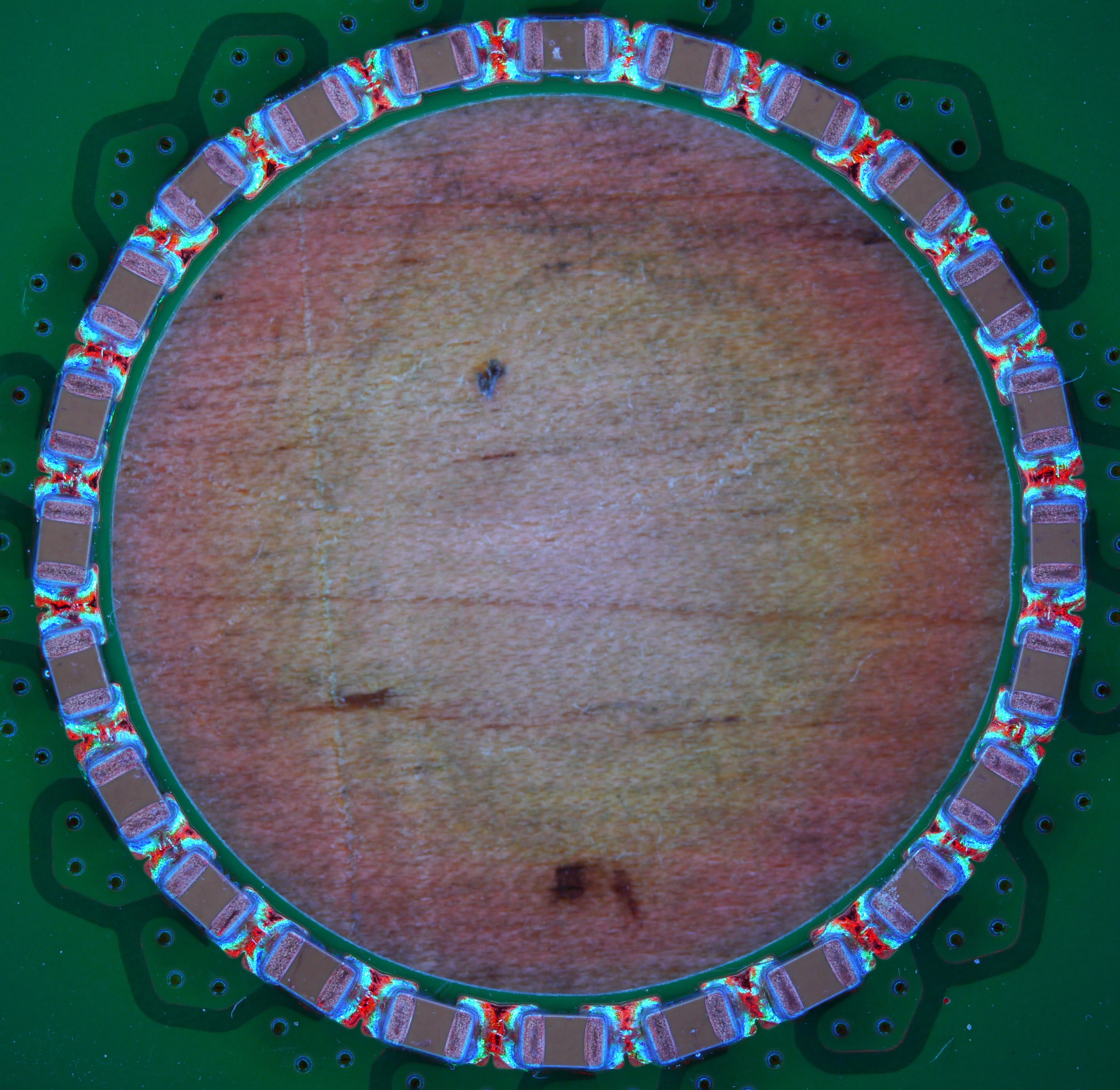
Here's an upcoming project- a PCB motor. You'll hear more about this one later this week. I think the pattern is neato and perfectly exploits surface tension to form a rugged assembly. Unfortunately, it fried one of my three-phase motor drivers so I'll need to figure out what to do about that.
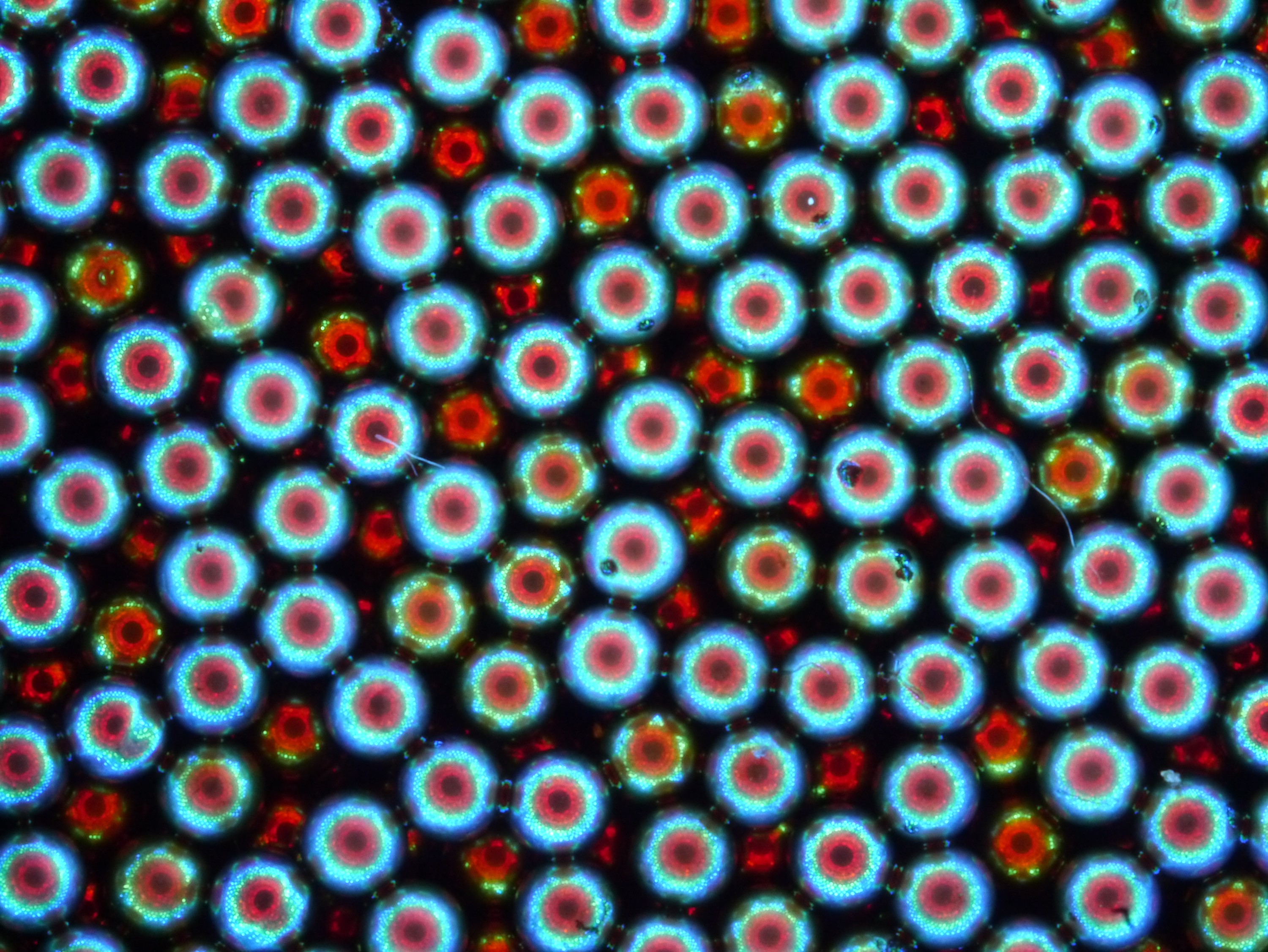
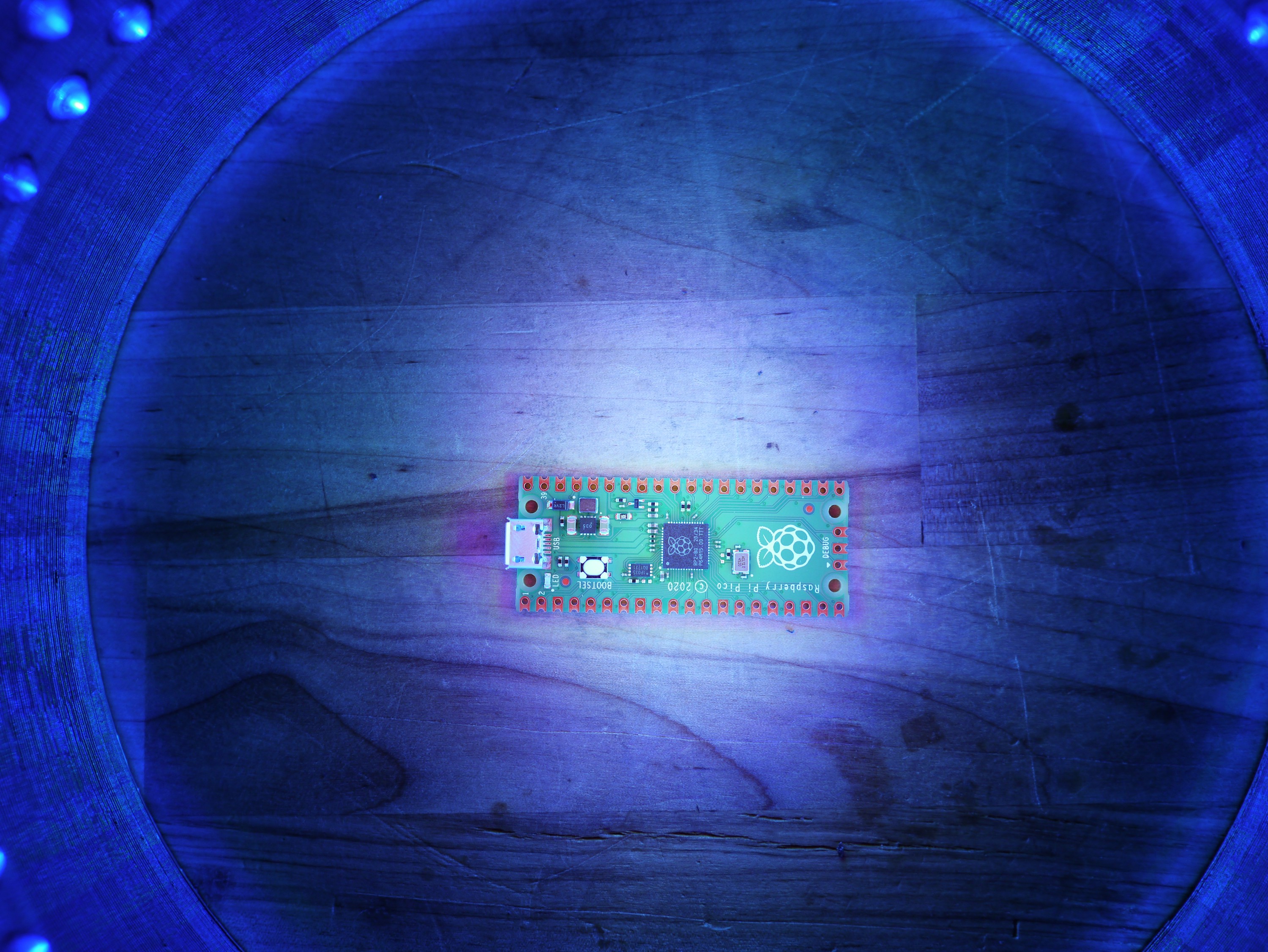
I got a jar of ball bearings and got these eye-hole like shots. Forbidden caviar, anybody?
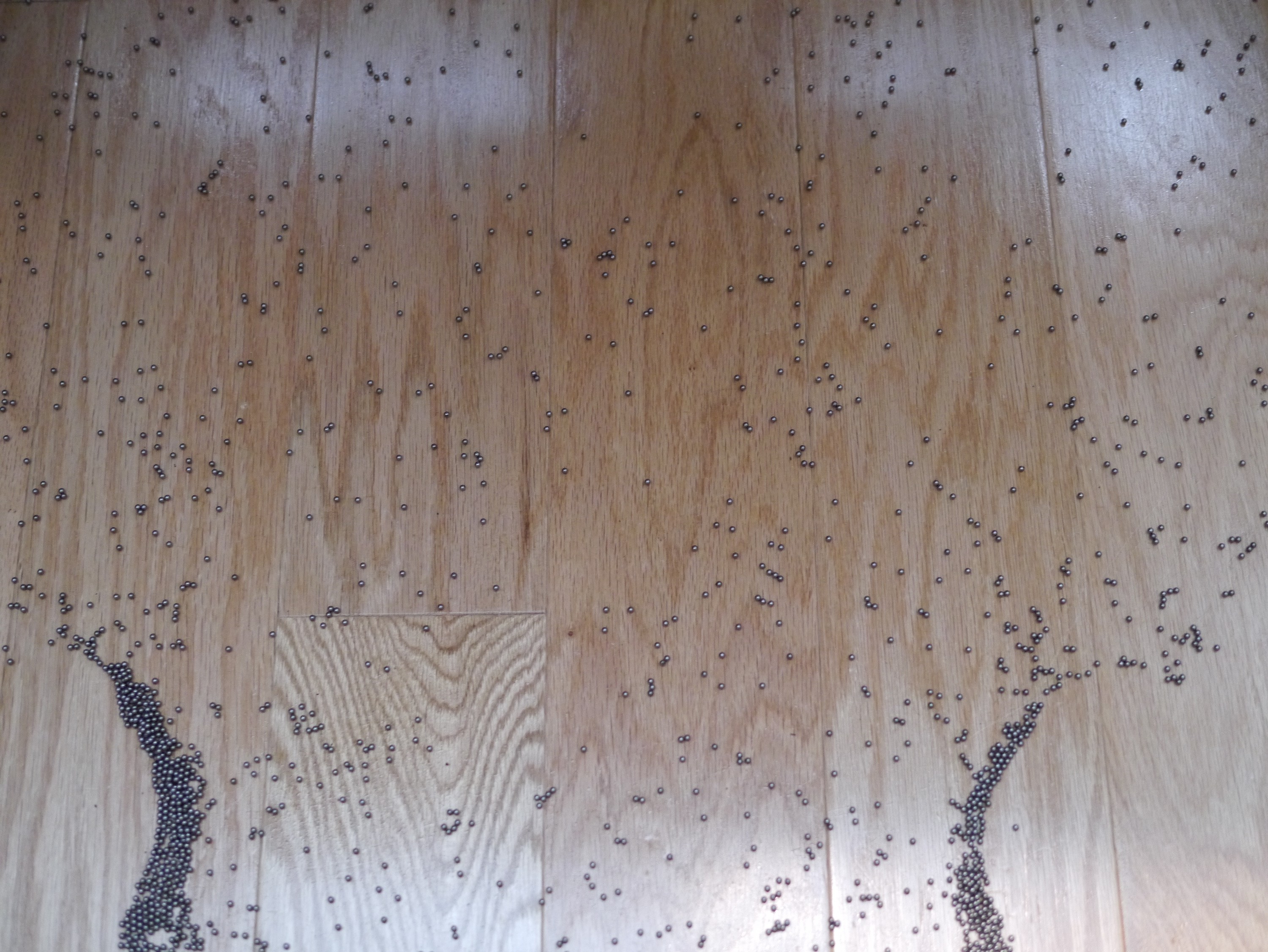
And here's the jar after I took the dome off horizontally
There was a pound of bearings there. After I clean that up, I'll be designing a 1m diameter dome with laser-cut black acrylic to take portraits. Maybe I can take it to the TC pride parade this year for portraits!
I wanna help more people use this in their photography, so I'd be willing to set up a Tindie or eBay kit with the LED's you'd need for about $10-$20 and fully assembled for maybe $50 depending on the interest. The domes take a full day to print, so that's where most of the cost comes from. I want you to do it yourself though, so have fun with those files!
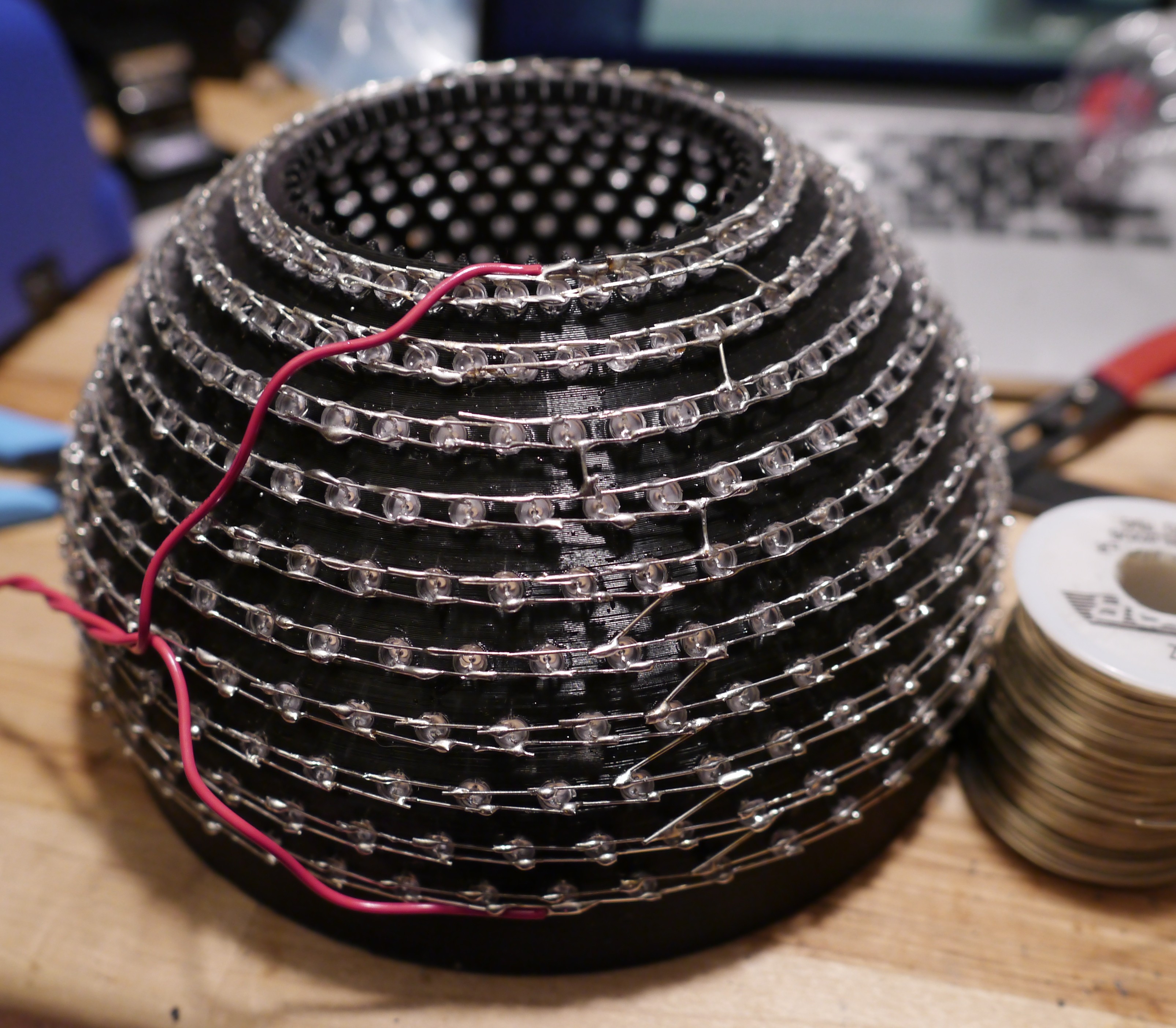
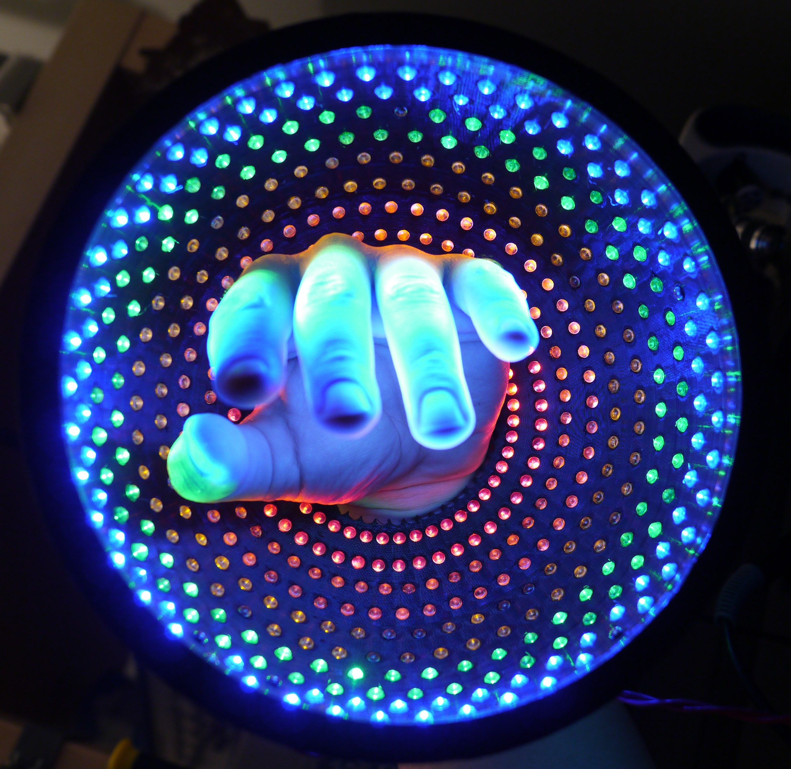
The low material variant printed successfully after fiddling with parameters, needing to jump to middle slicing tolerance. This variant has a 6 inch radius which allows you to stick your hands underneath and this to be suspended overhead. It uses 100 grams of filament but takes more than a day to print! I used extra fine features, but in the end it was kind of worth it because they fit with a medium amount of effort. Not as bad as the inclusive slicing tolerance, but not as smooth as the exclusive slicing tolerance.
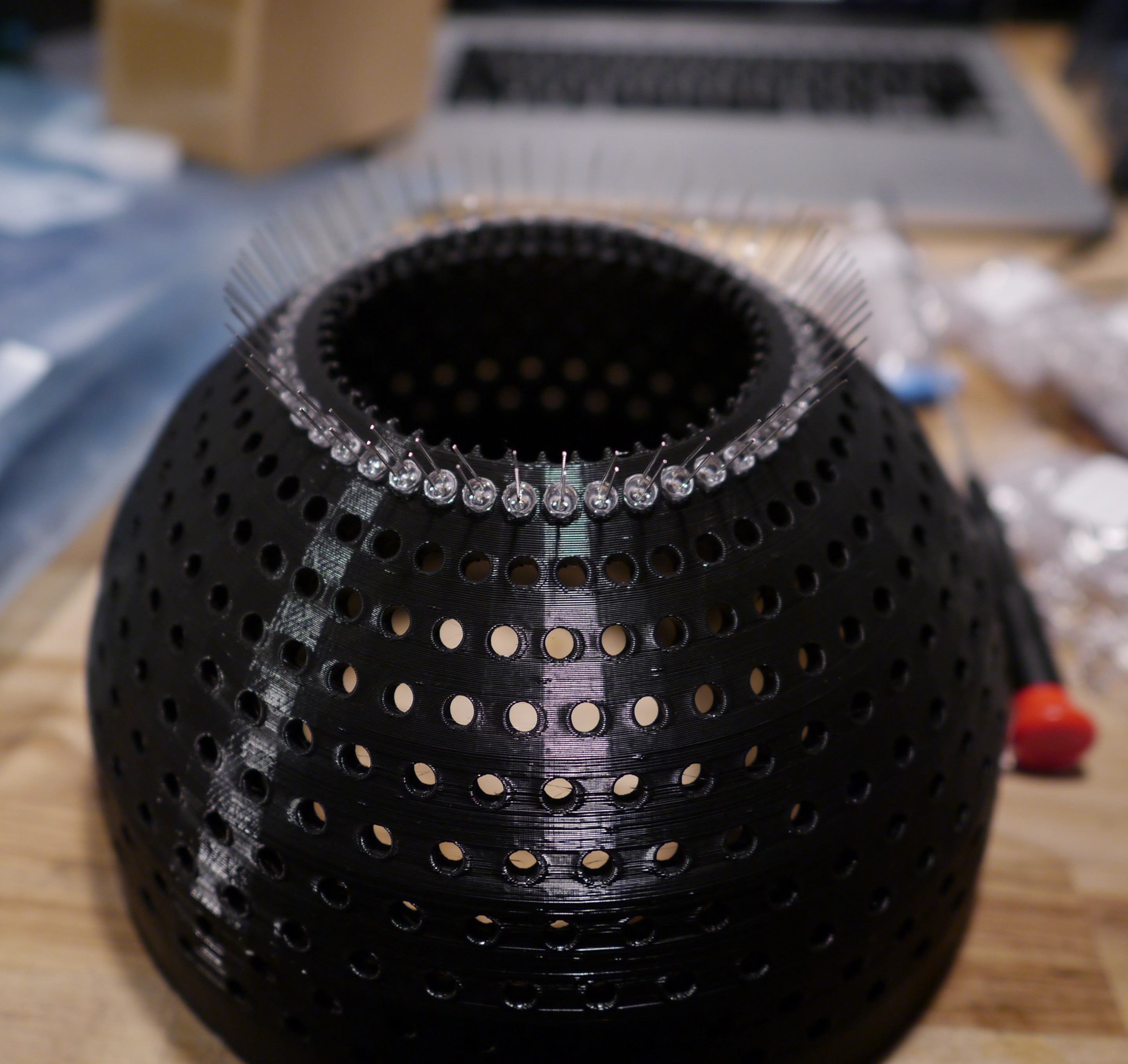
After a few days of sore fingers, I just went for it. The holes were so tight that it was a real effort to push the LED's in. But, I just pushed them in using a crescent wrench to get even pressure on the back. Here's the first row inserted with cathodes below anodes.
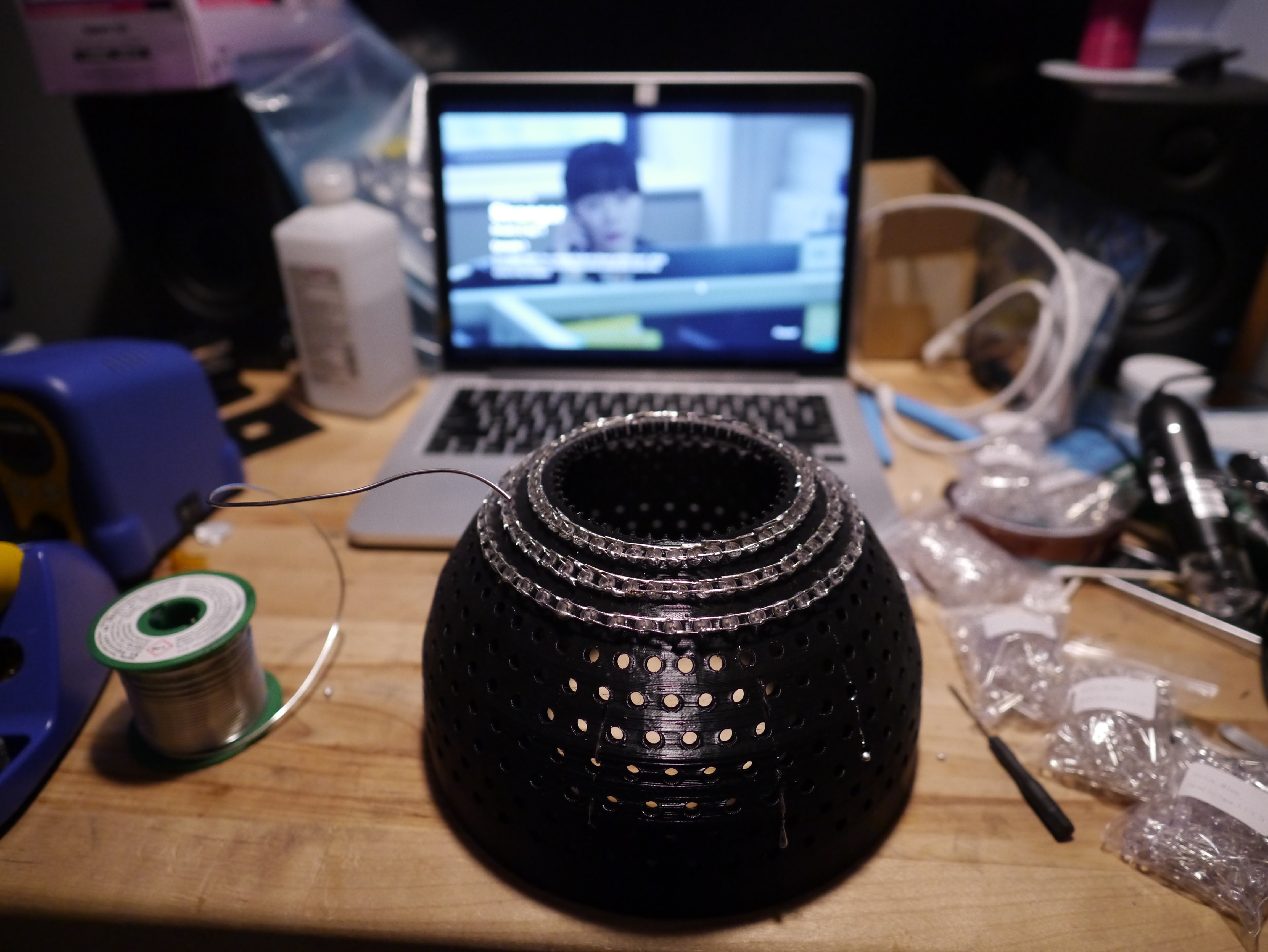
A few rows inserted and soldered...
The show "Stranger" on Netflix is pretty good. You should check it out.
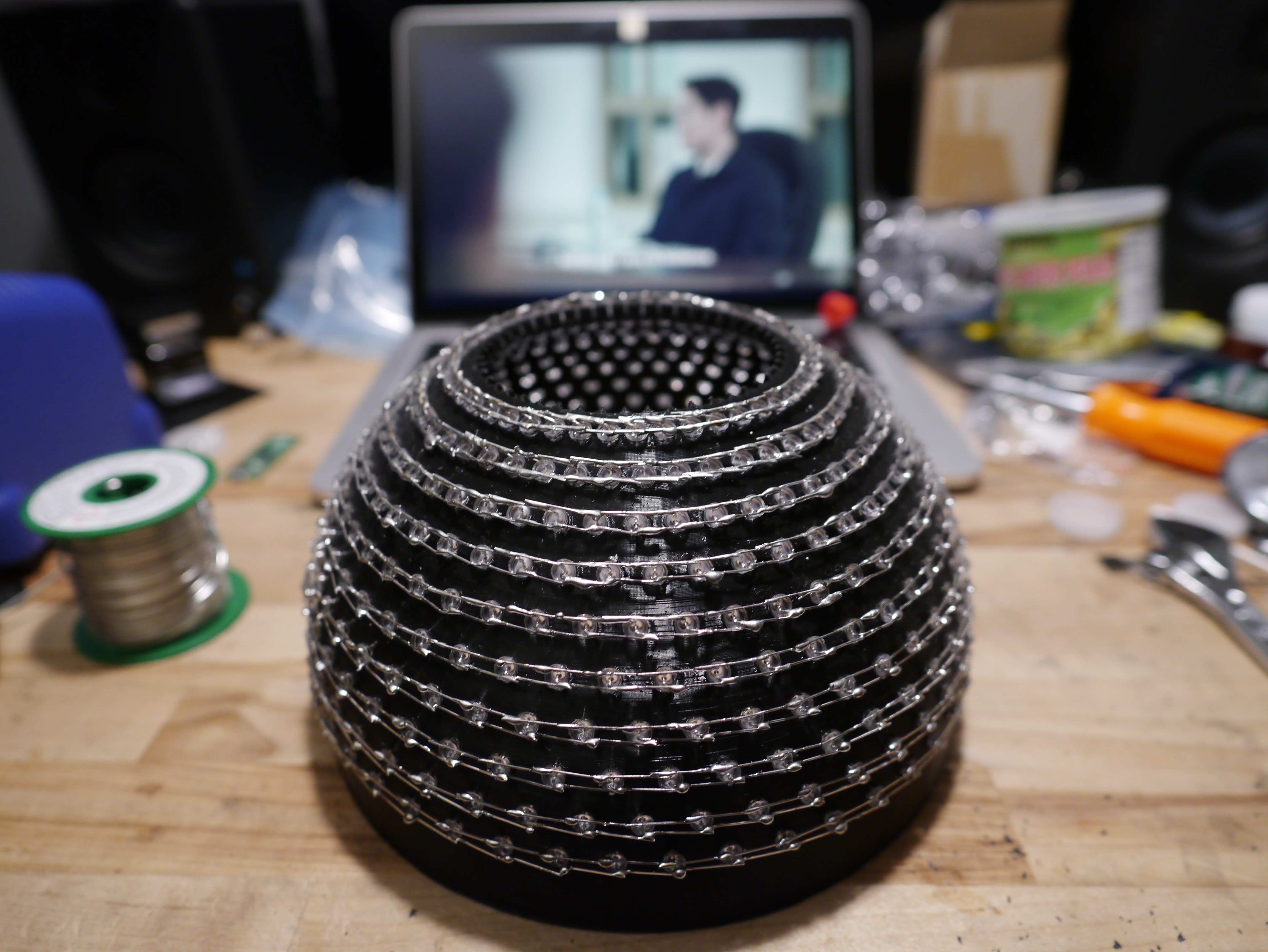
After a few episodes, I was done!
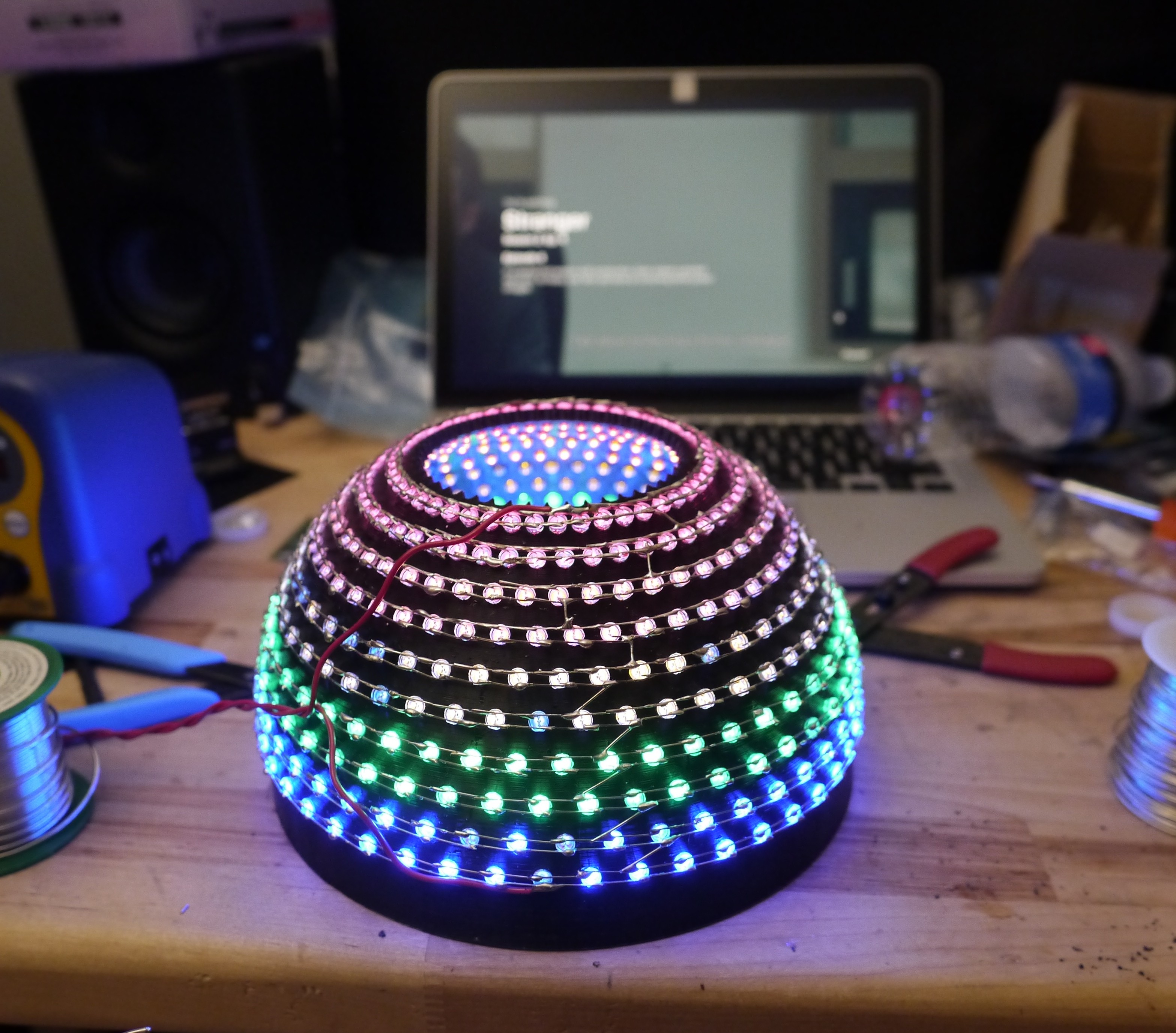
Then, the serial connection
And with the power supply carefully applying 21V,
Imagine waking up to this, lol
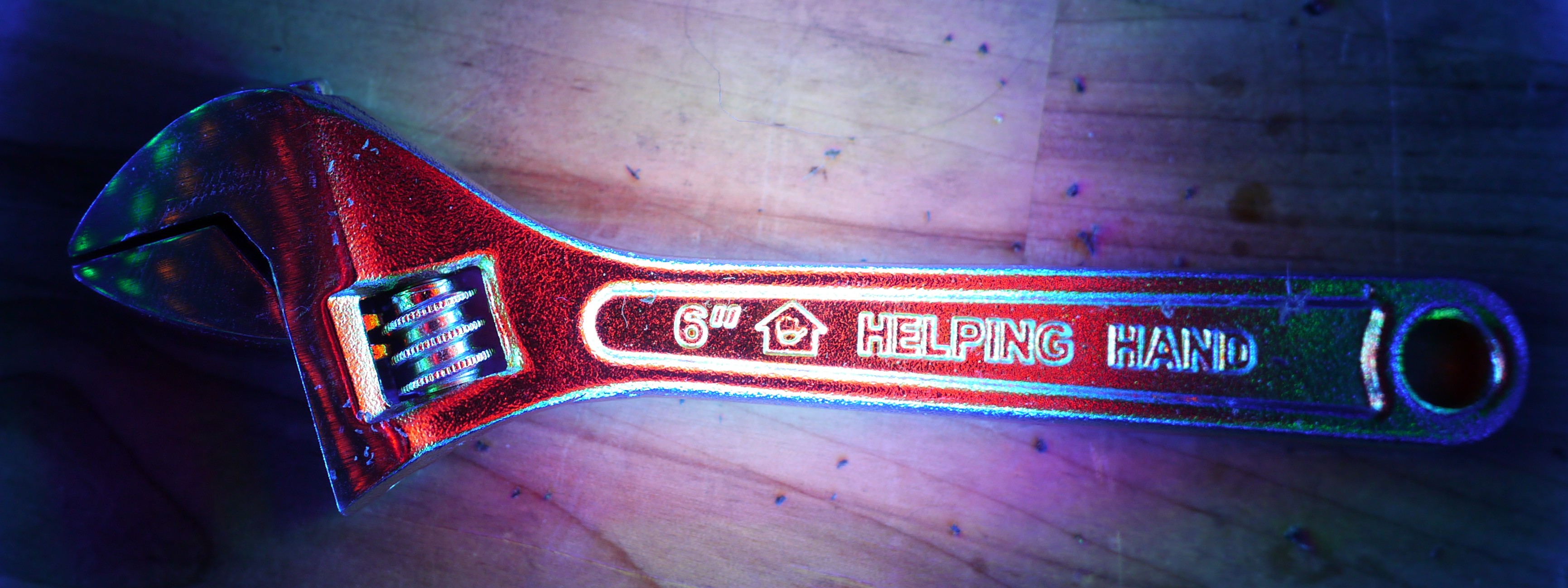
Okay, but here's the helping hand that helped me push all those LED's in place.
And let's pick something popular to test this out with... hmmm...
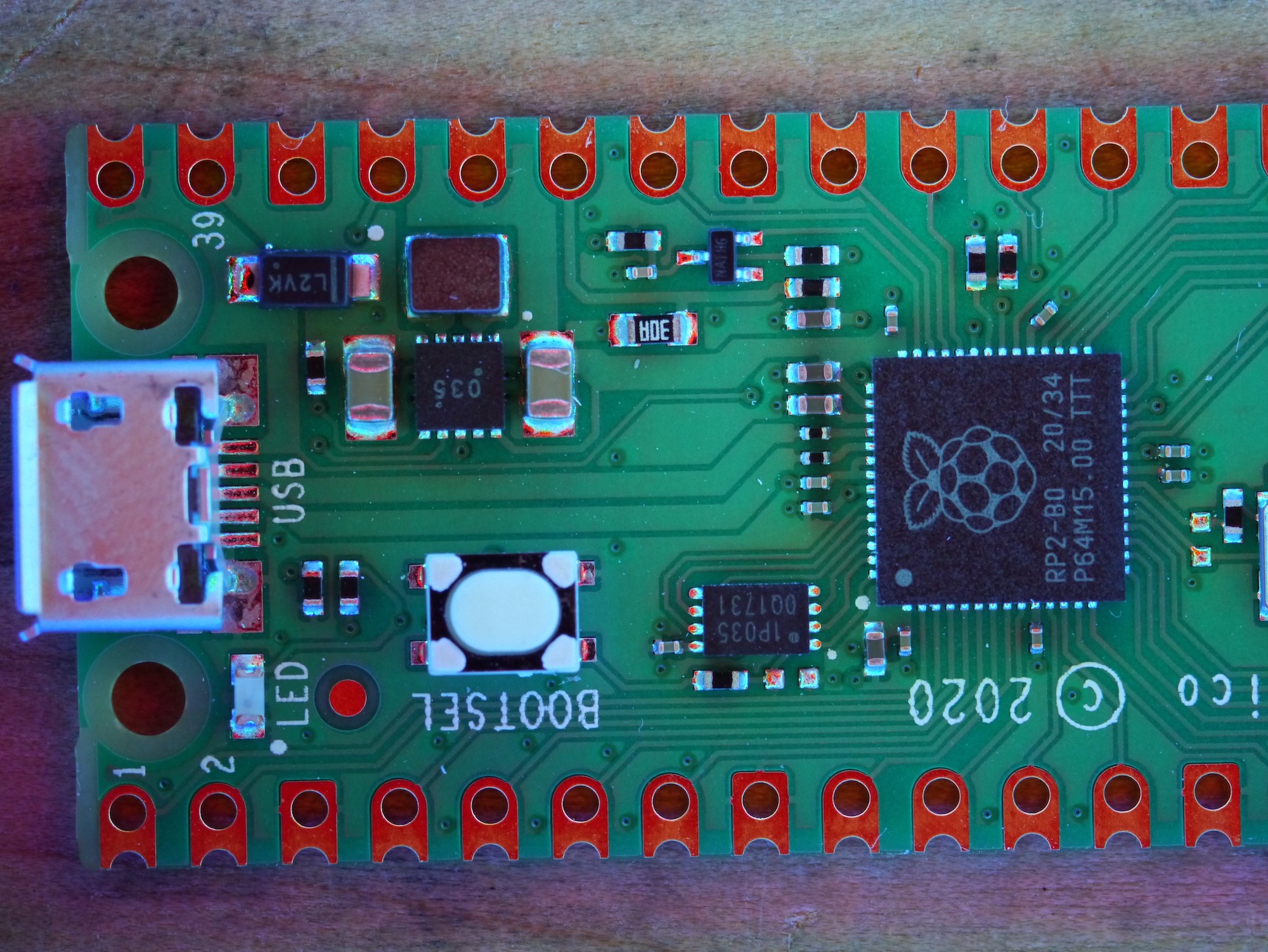
And with the macro lens, the fake Arduino looks really good.
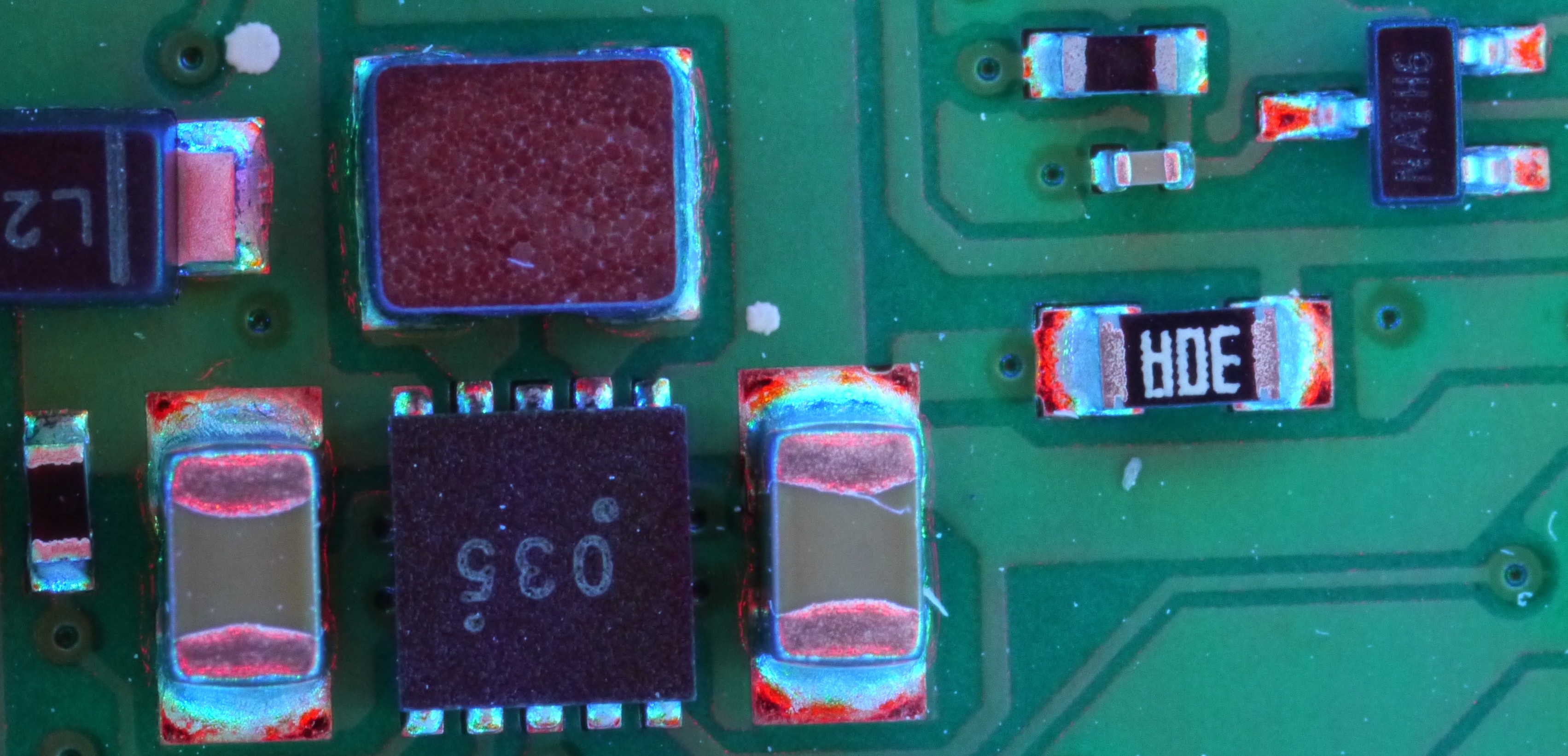
Let's check out some of these joints.
If you look at the SOT package on the upper right (3 leads), you can see the smooth rainbow transition due to the long pad transition area. The same applies to the resistors and capacitors. However, the DFN package marked "035" has uneven lead formation. Specifically, notice how the fillet on the upper middle pin is radiused instead of filleted like the adjacent pads because the adjacent pads were able to use the traces leading to the inductor to wick into the pad. Alternatively, the inductor could just be blocking the light and not showing a smooth fillet.
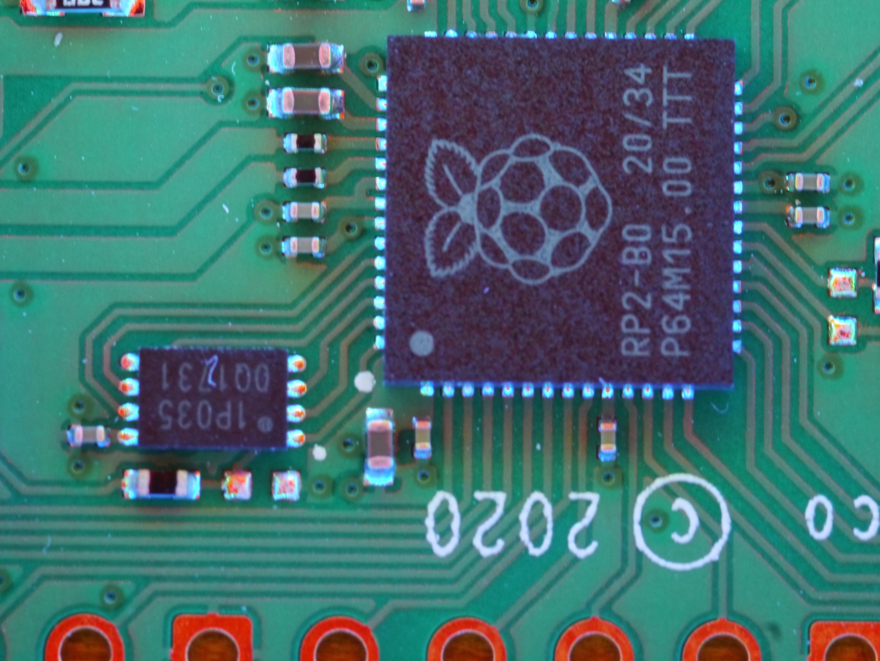
On the DFN ROM chip, you can see uniform, well formed joints. The light produces an interesting glow. You can even make out the lighting variations on the copper and soldermask thickness variations as well. It's a very fun lighting process!
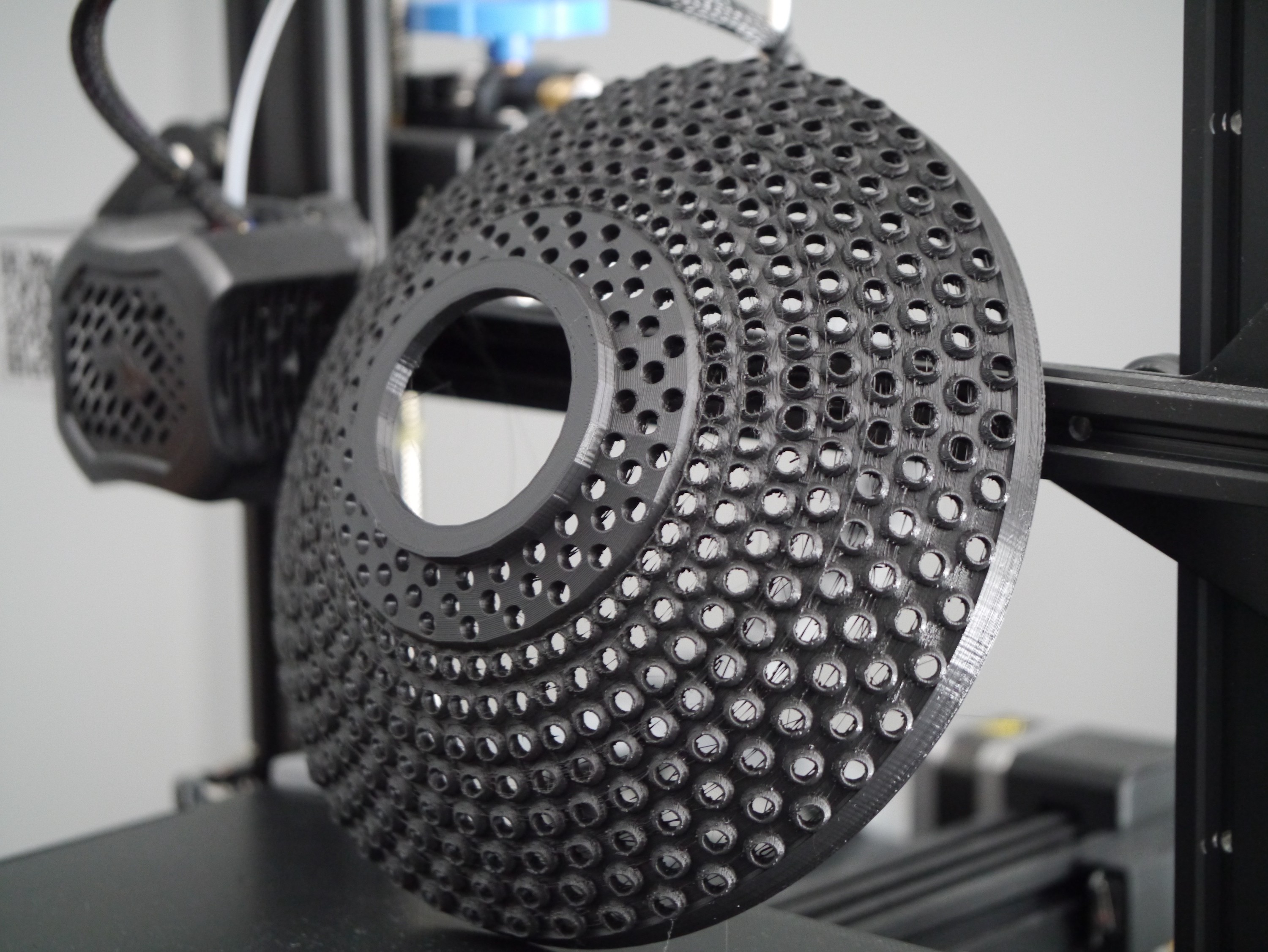
The print just completed and I wanted to make a few notes about tolerance.
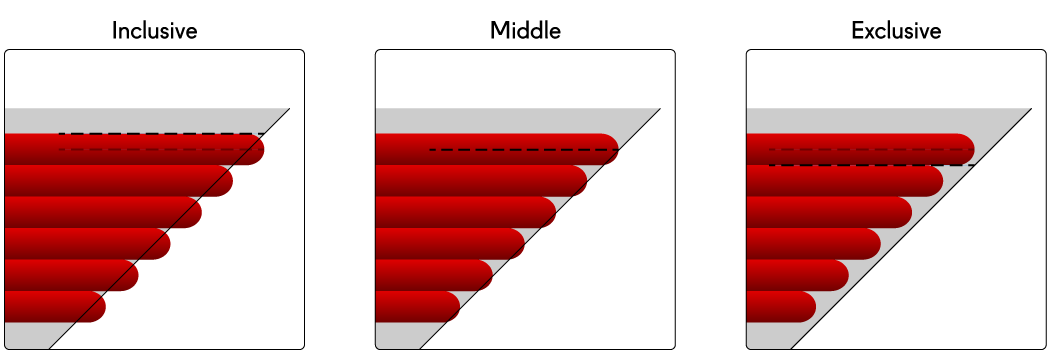
Tolerance of others lifestyles is critical for being a good person, but tolerances on 3D printed parts are not essential for being a good person. No matter what you do, mis-fitting parts are destined to print on fresh, untested settings. I designed with this in mind and tossed in a 0.2mm hole oversize. Cura also has a setting called "slicing wall tolerance" which allows for exclusive, inclusive, and middle slicing tolerances.
As you can tell, for fitting 5mm LED's through 5mm holes, I should have used exclusive tolerances. The problem is, I did and it still didn't fit. On such a large print, you can't afford layer adhesion issues, so the surefire solution to preventing that is to boost your extrusion and over-extrude by setting infill "flow" to 125% and wall flow to 110%. Unfortunately that resulted in holes that are *just* too snug.
 Sina Roughani