-
Certifiable
10/29/2024 at 02:46 • 0 commentsNow all three versions are open-source hardware certified by the Open Source Hardware Association.
![Beeping Blinking Badge Buddy US002688 Beeping Blinking Badge Buddy US002688]()
Beeping Blinking Badge Buddy ![B4 Handy US002689 B4 Handy US002689]()
B4 Handy ![Beeping Blinking Business-card Badge US002690 Beeping Blinking Business-card Badge US002690]()
Beeping Blinking Business-card Badge -
Brass buzzer in action
06/30/2024 at 18:22 • 0 commentsI got some brass piezo buzzers and assembled the third flex circuit. Brass is much easier to solder to than stainless steel, but it t still took a little extra time on the disc. Here is video of the card in action:
The capacitance is a little higher and the impedance a bit lower than the stainless steel buzzer so I needed to up the bulk capacitor to get it to play reliably.
-
RTFM
06/26/2024 at 02:57 • 0 commentsPart of the excitement getting the 1mm version of the card ready in time was the last minute issues. A few days before, it wasn't looking good.
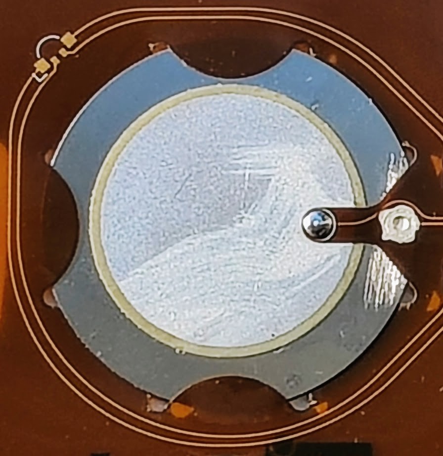
I came up with a nifty way to snap the piezo co-planer into the flex circuit to achieve a 1mm thick beeper. The weekend before Crowd Supply Teardown, I started to assemble everything. It was all going fairly well at first. I had purchased OSH Stencil with the OSH Park flex and I have the Miniware MHP30 so the tiny leadless packages were not too intimidating. The fun part came when I tried to solder in the piezo.
It seemed to stick to the center pad, but for the life of me I could not get it to solder to the outer ring. I tried and tried and no matter how much I cooked it nothing would stick to the disk. I took the disk away from the flex, scuffed it, globbed on flux and cranked up the iron but nothing would stick. In a moment of desperation, I decided to look up the part number to check the datasheet. Then I discovered that I had ordered a piezo buzzer built on a stainless steel disk. They claim it is possible to solder with special solder and flux, but I wouldn't know as that is not what I had on hand.
I was trying to find a way to remedy this in time for the event. I was afraid that I may still struggle with a brass disc, and didn't know how fast I could get one. I thought that maybe I can find a solderless way to make contact. I looked for some conductive glue on Amazon and found a few including this silver conductive paste available Amazon prime: https://a.co/d/0i3swAch
When it arrived I assembled the second bare flex circuit (the first was cooked beyond utility). Before sliding the piezo in, I sanded the disk to make sure there was something for the paste to grab, and then slid it into the flex. The center contact was not difficult to solder so I soldered it to hold the tab in place while gluing. I then applied some of the paste to the second contact and made sure it went through the hole to reach the disk. It said you could cure it faster with heat, so used my heat gun on it for just a little and walked away a couple hours to let it finish setting.
A couple hours later I came back and tapped the antenna with my phone, and heard some of the most delightful tones emerging from the 1mm thick beeping, blinking business-card badge. What a relief.
![]()
-
Quick Update
06/25/2024 at 03:20 • 0 commentsHere is a sneak peak at the 1mm Beeping Blinking Business-card Badge. I got it running just in time for Crowd Supply Teardown 2024. Stay tuned for more details. I also received the B4Handy fabs from OSH Park.
![]()
![]()
![]()
-
A full sized hand-solderable version (B4Handy)
05/26/2024 at 15:24 • 0 commentsI'm a fan of the compact version, but I realize some people may want to make their own full size card. I also realize that these are likely to get built in small quantities and often hand assembled, so I created a full-size hand-solderable version.
![]()
The back side is blank with only the antenna (under soldermask), the programming header, and a hole for the LED to shine through. You can order the design from OSH Park, or get the design files on GitHub.
With the design files, you can add your own customization. The antenna will be mostly invisible behind soldermask, unless you want to show it off and opt for the clear soldermask "After Dark" option at OSH Park.
You could also customize the card with a label. Business-card size labels are readily available and then you can create your own full color design. The label should not affect the antenna, and the LED should shine through if you don't color it too darkly. Be sure to include some indication where they need to tap.
The header footprint in this design staggers the pins to allow for a friction fit for programming. I'll post a picture of the design when it gets back and let you know how the staggered pins are working.
-
A thinner card and a compact version
05/12/2024 at 04:16 • 0 commentsI'm working on a thin implementation aiming at 1mm.
A flex circuit with QFN devices should come in just under 1mm.
I've got a design and I'm waiting on the QFN MCU to assemble them.
In the mean time, I thought it might be nice to have smaller SAO version. The NFC EEPROM and CH32V003 are available in SOIC-8 package that is easy to assemble by hand, and they both fit nicely inside the space of the NFC PCB antenna. This will also make a convenient board for firmware development until the thin flex circuit version gets here.
8 pins on the MCU is plenty for an SAO. 2 pins for power, 2 for I2C, and 2 for the buzzer. That leaves two for the RGB LED. The serial controlled LEDs draw too much power to be useful with the NFC harvested energy, but you can drive 3 LEDs with two GPIO. I used the same trick I used on my KUIIC board https://hackaday.io/project/183092/log/201387-full-color-dimmable-rgb-led-with-only-two-pwm-outputs
This smaller version turned out great and the WCH chip can play a nice tune from the harvested power. It also fits better in a pocket. Design files are on github: https://github.com/gsteiert/nfcwchsao
![]()
-
Power Estimates
07/30/2023 at 23:41 • 0 commentsI assembled two of the test boards, one with ST25DV and the other with NT3H2211, then took some measurements with different loads.
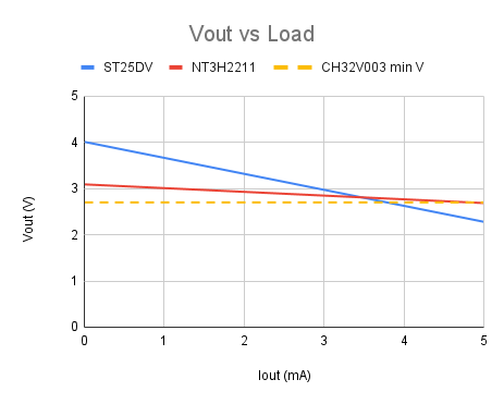
Turns out the ST25DV does not regulate the output voltage, and it drops off with load fairly steeply. The NT3H2211 is better regulated, and maintains the voltage better when loaded.
The CH32V003 needs at least 2.7V to run and will consume between 2.3 and 1.9 mA depending on how many peripherals are enabled.
The measurements are listed below and a plot of the output voltage vs load curve fit to the measurements. This shows that the NT3H2211 provides a much more consistent voltage and stays above the minimum 2.7V up to a higher load current. This suggests it will be easier to power the CH32V003 and a few peripherals with the NT3H2211, but there is not much margin.
I hear they are coming out with a low power CH32L103. I wonder how the price of that will compare to the CH32V003. It is available in the same TSSOP20 pin package, but it has more memory and advanced features like USB, which is not a requirement in this case.
Load ST25DV NT3H2211 No Load 4.01 3.09 1000 Ohm 2.72 2.82 500 Ohm 2.37 2.66 ![]()
-
Course Correction
07/30/2023 at 03:41 • 0 commentsIt has been a while since I posted on this project. I had some inspiration at CrowdvSupply Teardown 2023 and have been putting in some more time on this. I’ve got a few issues with the NXP micro. It only generates 1.8V from NFC which is only enough to drive a red LED without a voltage doubler. It is also missing support from their SDK on GitHub.
With the WCH CH32V003 available for about a dime in volume, I could use it with a I2C NFC EEPROM for about the same price, and drive an RGB LED without a voltage doubler. The CH32V003 is not specifically a low power device, so I decided to see if it would be feasible to drive this from the NFC harvested power. It only runs down to 2.7V, so I need to know if the NFC chips can deliver that when loaded. There are a few options available with energy harvesting output. I’ve used the ST25DV in the past, and NXP has a couple similar devices like the NT3H2211, or NTP53321. The data sheets are pretty sketchy on how much power is available, so I decide to measure it for myself.
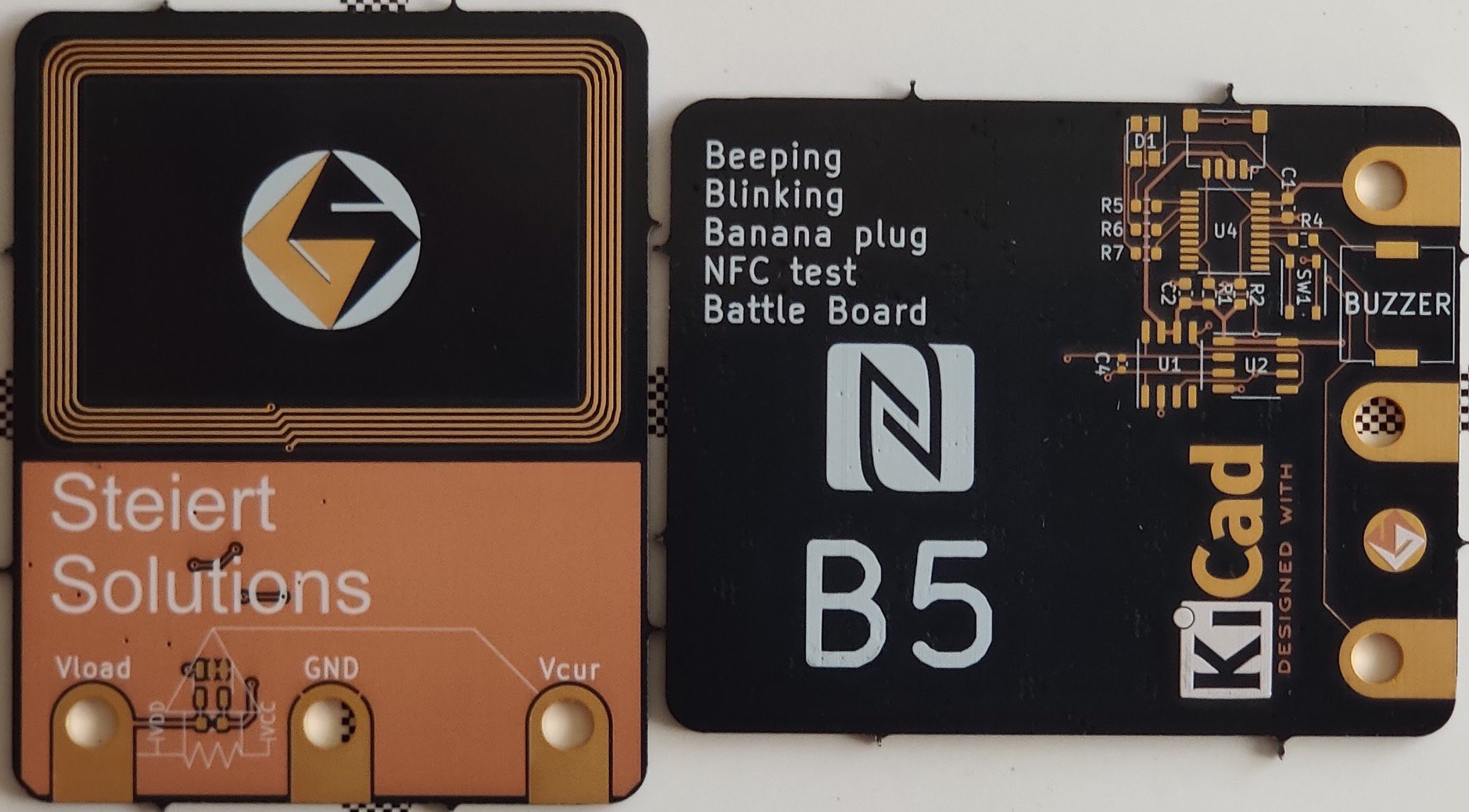
I designed a board to test a couple of the device. The ST25DV and NT3H2211 are both designed with 50pF load capacitance, but the NTP53321 is designed for a different load cap, so it would require a different tuned antenna. I already have an antenna I’ve used for 50pF load, so I designed a board to test the two 50pF chips. Unfortunately they have different pin outs, so I had to put down two footprints in parallel. I added the CH32V003 and a current sense amp so I could see how much current it is using. I used my badge as a template and shrank it to save a little on the OSHPark price. I kept the bannana plug/alligator clip pads for measuring voltage and current. I’ll share more about what I found in another post.
![]()
-
More details on B5
04/20/2021 at 01:19 • 0 commentsMy progress been delayed by samples getting stuck in customs. I would have preferred to have tested out the design before sharing more, but I can at least provide some of the theory of the design that I ordered from OSH Park. It looks really good in after dark.
![]() Here is the schematic for the design:
Here is the schematic for the design:![]() As I mentioned in the last post, I included two buzzers as a stuffing option. You can see how they overlap in the picture of the board.
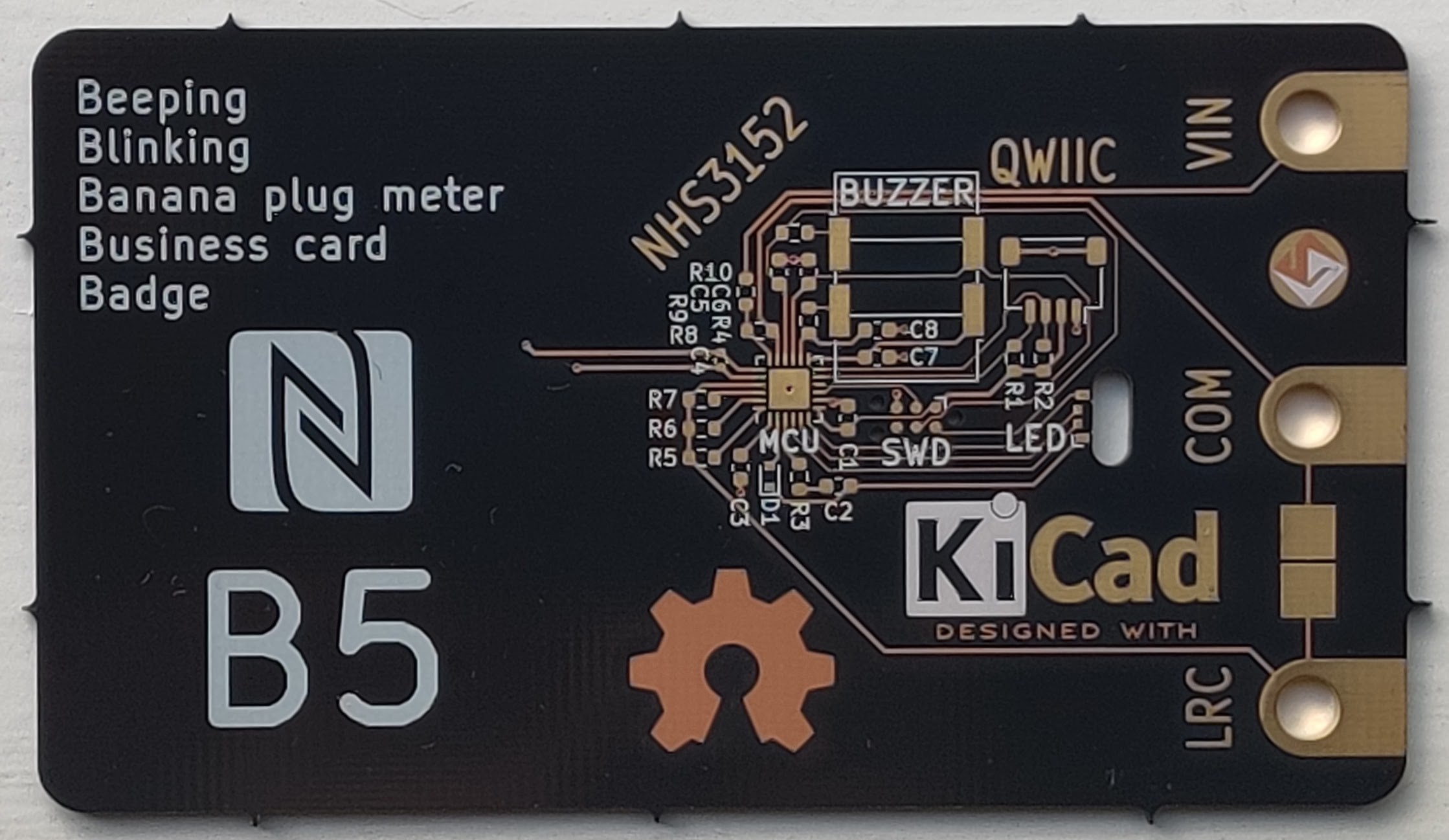
As I mentioned in the last post, I included two buzzers as a stuffing option. You can see how they overlap in the picture of the board.
Another interesting thing to note are the three resistors, R5-7. These are another stuffing option I will be testing. As shown they are three different load resistors that I could use for impedance measurements. I am hoping that the loading of the current to digital circuit will be sufficient for my measurements so that these are not needed. If they are not needed as loads, I may use them as reference values for calibrating the impedance measurements. I expect reference impedances will be more useful than the programmable loads.
The current to digital circuit measures current integrated over time which is perfect for counting coulombs into a capacitor. The voltage rise per coulomb is proportional to the capacitance. -
A Dilemma, A Hedge & A Hack
03/25/2021 at 03:04 • 0 commentsTo improve performance while operating from harvested power, the LPC8N04/NHS3152 suggest adding decoupling capacitors to a couple of the high drive GPIO pins. There are four high drive GPIO pins that also happen to be the timer/PWM pins. This allows us to use two for decoupling and two for the piezo buzzer. The dilemma is that the SWD signals are also on two of these high drive GPIO, so I have to choose: do I want to give up decoupling or buzzer when I am programming/debugging?
I can provide power externally when programming/debugging, so I could easily give up the decoupling, but SWD may not work with the capacitors installed, so I may need to add and remove them often. On the other hand, I only need to remove a single resistor to eliminate the load of the piezo buzzer, and if I use a large enough series resistor, SWD may even work with the resistor present. But, if I share the buzzer with SWD, I can't use them at the same time. To hedge my bets, I will put decoupling caps and a buzzer on both pairs so I can extend my indecision until I assemble the boards.
The buzzer is one of the largest parts on the board, so adding a second one adds bloat, but there is really no point installing them at the same time so they can share some space. I placed them so they overlap on the board. You might think the hack is ignoring all the placement errors in KiCad, but the real hack is that the silkscreen for the buzzers goes right over the pads for the other buzzer. I know that OSH Park clears silkscreen off pads so I left it there. I can clean it up in the next pass when I figure out which stuffing option to keep.
Beeping, Blinking Business-card Badge (B4)
Second generation of the NFC business card adding audible feedback
 greg
greg




 Here is the schematic for the design:
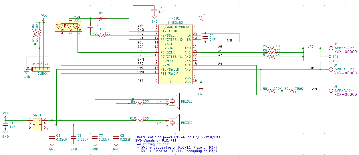 As I mentioned in the last post, I included two buzzers as a stuffing option. You can see how they overlap in the picture of the board.